Page 1366 of 2267
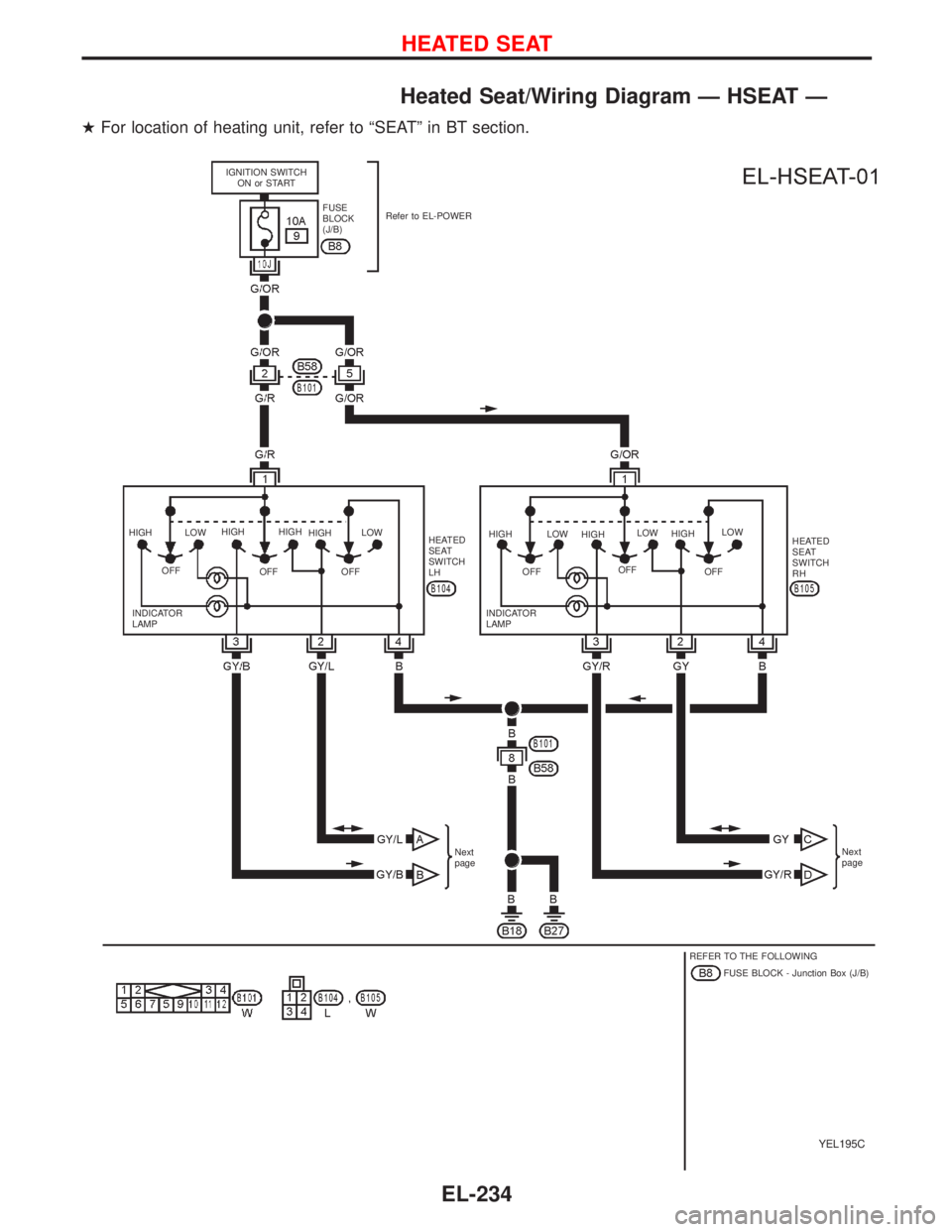
Heated Seat/Wiring Diagram—HSEAT—
�For location of heating unit, refer to“SEAT”in BT section.
YEL195C
IGNITION SWITCH
ON or START
FUSE
BLOCK
(J/B)Refer to EL-POWER
HIGH
OFFLOWHIGH
OFFHIGH
HIGH
OFFLOW
HEATED
SEAT
SWITCH
LHHIGH
OFFLOW
HIGH
OFFLOW
HIGH
OFFLOW
HEATED
SEAT
SWITCH
RH
INDICATOR
LAMPINDICATOR
LAMP
Next
pageNext
page
REFER TO THE FOLLOWING
FUSE BLOCK - Junction Box (J/B)
HEATED SEAT
EL-234
Page 1375 of 2267

Trouble Diagnoses
Symptom Possible cause Repair order
None of the power windows can
be operated using any switch.1. 40A fusible link and circuit
breaker-1.
2. Grounds
B18andB27.
3. Power window relay.
4. Open/short in power window
main switch circuit.1. Check 40A fusible link (letter
e,located in fuse
and fusible link box) and circuit breaker-1. Turn
ignition switch to“ON”position and verify battery
positive voltage is present at terminal
�12of
power window main switch, and other switches as
follows.
2. Check grounds
B18andB27.
3. Check power window relay.
4. Check W/R wire between fuse block (J/B) and
power window main switch for open/short circuit.
Driver’s side power window can-
not be operated but other win-
dows can be operated.1. Driver’s side power window
regulator circuit.
2. Driver’s side power window
regulator.1. Check driver’s side power window regulator circuit
2. Check driver’s side power window regulator
One or more passenger power
windows cannot be operated.1. Power window switches (front
sub-switch, rear sub-switch
RH, rear sub-switch LH).
2. Power window regulators.
(Passenger side, rear LH,
rear LH.)
3. Power window main switch.
4. Power window circuit.1. Check power window switches (front sub-switch,
rear sub-switch RH, rear sub-switch LH)
2. Check power window regulators (front sub-switch,
rear sub-switch RH, rear sub-switch LH)
3. Check power window main switch
4-1. Check harnesses between power window main
switch and power window sub-switches for
open/short circuit.
4-2. Check harnesses between power window sub-
switches and power window regulators for open/
short circuit.
One or more passenger power
windows cannot be operated
using power window main switch
but can be operated by power
window sub-switches.1. Power window main switch. 1. Check power window main switch.
Driver’s side power window auto
function cannot be operated
using power window main switch.1. Power window main switch. 1. Check power window main switch.
Location of sub-switch Terminals
Passenger
�5
Rear RH�5
Rear LH�5
POWER WINDOW
EL-243
Page 1497 of 2267
Engine Compartment
YEL234C Front wiper motor (LHD models)
ABS actuator and electric unit
(Control unit)Relay boxFront wiper motor (RHD models)
Glow relay (CD engine models) Fusible link and fuse box
Cooling fan relay-1 Headlamp relay LH
Horn relay
Cooling fan relay-3
Accessory relayCooling fan relay-2 or power fuse
Air conditioner relay
Headlamp relay RH
Front wiper relayGlow relay
(CD engine models)
Rear wiper relayPark/Neutral position relay ECM relay
LOCATION OF ELECTRICAL UNITS
EL-365
Page 1808 of 2267
.
p2Fusible link
lThe double line shows that this is a")
Description
Number Item Description
p1Power conditionlThis shows the condition when the system receives battery positive voltage
(can be operated).
p2Fusible link
lThe double line shows that this is a fusible link.
lThe open circle shows current flow in, and the shaded circle shows current
flow out.
p3Fusible link/fuse locationlThis shows the location of the fusible link or fuse in the fusible link or fuse
box. For arrangement, refer to EL section (ªPOWER SUPPLY ROUTINGº).
p4Fuse
lThe single line shows that this is a fuse.
lThe open circle shows current flow in, and the shaded circle shows current
flow out.
p5Current ratinglThis shows the current rating of the fusible link or fuse.
p6Connectors
lThis shows that connectorE3is female and connectorM1is male.
lThe G/R wire is located in the 1A terminal of both connectors.
lTerminal number with an alphanumeric reference (1A, 5B, etc.) indicates that
the connector is an SMJ connector.
p7Optional splicelThe open circle shows that the splice is optional depending on vehicle appli-
cation.
p8SplicelThe shaded circle shows that the splice is always on the vehicle.
p9Page crossinglThis arrow shows that the circuit continues to an adjacent page.
lThe A will match with the A on the preceding or next page.
p10Common connectorlThe dotted lines between terminals show that these terminals are part of the
same connector.
p11Option abbreviationlThis shows that the circuit is optional depending on vehicle application.
p12RelaylThis shows an internal representation of the relay. For details, refer to EL sec-
tion (ªSTANDARDIZED RELAYº).
p13ConnectorslThis shows that the connector is connected to the body or a terminal with bolt
or nut.
p14Wire color
lThis shows a code for the color of the wire.
B = Black BR = Brown
W = White OR = Orange
R = Red P = Pink
G = Green PU = Purple
L = Blue GY = Gray
Y = Yellow SB = Sky Blue
LG = Light Green CH = Dark Brown
DG = Dark Green
When the wire color is striped, the base color is given first, followed by the
stripe color as shown below:
Example: L/W = Blue with White Stripe
p15Option descriptionlThis shows a description of the option abbreviation used on the page.
p16Switch
lThis shows that continuity exists between terminals 1 and 2 when the switch
is in the A position. Continuity exists between terminals 1 and 3 when the
switch is in the B position.
p17Assembly partslConnector terminal in component shows that it is a harness incorporated
assembly.
p18Cell codelThis identifies each page of the wiring diagram by section, system and wiring
diagram page number.
HOW TO READ WIRING DIAGRAMS
GI-13

ABS actuator and electric unit
(Control unit)Relay boxFront wiper motor (RHD models)
Glow relay (CD engine models) Fusible link and fuse box
C")