1999 NISSAN PRIMERA clock setting
[x] Cancel search: clock settingPage 1134 of 2267

HEADLAMP - HEADLAMP AIMING CONTROL
(MANUAL) -................................................................. 87
Wiring Diagram - H/AIM - ........................................ 87
HEADLAMP - HEADLAMP AIMING CONTROL
(AUTO) -....................................................................... 91
System Description .................................................. 91
Initialisation .............................................................. 91
Component Parts and Harness ............................... 92
Wiring Diagram - H/AIM - ........................................ 93
Trouble Diagnosis .................................................... 95
Removal and Installation ......................................... 99
PARKING, LICENSE AND TAIL LAMPS.................. 100
Wiring Diagram - TAIL/L - ...................................... 100
STOP LAMP.............................................................. 104
Wiring Diagram - STOP - ...................................... 104
BACK-UP LAMP........................................................ 107
Wiring Diagram - BACK/L - ................................... 107
FRONT FOG LAMP.................................................... 110
Wiring Diagram - F/FOG - ...................................... 110
Aiming Adjustment .................................................. 111
Bulb Specifications ................................................. 111
REAR FOG LAMP...................................................... 112
Wiring Diagram - R/FOG -...................................... 112
TURN SIGNAL AND HAZARD WARNING LAMPS.. 117
Schematic ............................................................... 117
Wiring Diagram - TURN - ....................................... 118
Trouble Diagnoses................................................. 123
ILLUMINATION.......................................................... 124
Schematic .............................................................. 124
Wiring Diagram - ILL - ........................................... 125
INTERIOR, SPOT, VANITY MIRROR AND
LUGGAGE ROOM LAMPS....................................... 130
System Description ................................................ 130
Schematic .............................................................. 131
Wiring Diagram - INT/L - ....................................... 132
BULB SPECIFICATIONS.......................................... 137
Headlamp............................................................... 137
Exterior Lamp ........................................................ 137
Interior Lamp.......................................................... 137
METER AND GAUGES............................................. 138
System Description ................................................ 138
Combination Meter ................................................ 139
Wiring Diagram - METER -/MODELS BEFORE
VIN - P11U0548750............................................... 141
Schematic .............................................................. 144
Wiring Diagram - METER -/M/T MODELS
AFTER VIN - P11U0548750.................................. 146
Wiring Diagram - METER -/CVT MODELS
AFTER VIN - P11U0548750.................................. 149
Combination Meter Self-Diagnosis ........................ 152
Trouble Diagnoses (Models before VIN -
P11U0548750) ....................................................... 155
Trouble Diagnoses (Models after VIN -
P11U0548750) ....................................................... 159
Fuel Level Sensor Unit Check............................... 164
QG & SR Engine Models ...................................... 164CD20T Engine Models .......................................... 164
Thermal Transmitter Check ................................... 164
WARNING LAMPS.................................................... 165
Warning Lamps/Schematic .................................... 165
Wiring Diagram - WARN - ..................................... 167
Electrical Components Inspection ......................... 179
WARNING CHIME..................................................... 180
System Description ................................................ 180
Wiring Diagram - CHIME - .................................... 181
Trouble Diagnoses................................................. 183
Electrical Components Inspection ......................... 185
FRONT WIPER AND WASHER................................ 186
System Description ................................................ 186
Wiring Diagram - WIPER - .................................... 188
Removal and Installation ....................................... 190
Front Washer Nozzle Adjustment .......................... 192
Front Washer Tube Layout .................................... 192
REAR WIPER AND WASHER.................................. 193
System Description ................................................ 193
Wiring Diagram - WIP/R -...................................... 195
Removal and Installation ....................................... 197
Washer Nozzle Adjustment ................................... 197
Washer Tube Layout ............................................. 199
Check Valve ........................................................... 199
HEADLAMP WASHER.............................................. 200
Wiring Diagram - HLC - ......................................... 200
Washer Tube Layout ............................................. 202
Check Valve ........................................................... 202
HORN, CIGARETTE LIGHTER AND CLOCK.......... 203
Wiring Diagram - HORN - ..................................... 203
REAR WINDOW DEFOGGER AND DOOR
MIRROR DEFOGGER............................................... 207
System Description ................................................ 207
Schematic .............................................................. 208
Wiring Diagram - DEF - ......................................... 209
Trouble Diagnoses................................................. 212
Electrical Components Inspection ......................... 213
Filament Check ...................................................... 213
Filament Repair ..................................................... 214
AUDIO........................................................................ 216
Anti-theft System ................................................... 216
Speed Dependent Volume Control ........................ 217
Personal Audio Settings ........................................ 217
Schematic .............................................................. 218
Wiring Diagram - AUDIO - ..................................... 219
Trouble Diagnoses................................................. 226
Inspection............................................................... 228
AUDIO ANTENNA..................................................... 229
Location of Antenna ............................................... 229
ELECTRIC SUNROOF.............................................. 230
Wiring Diagram - SROOF - ................................... 230
POWER DOOR MIRROR.......................................... 231
Wiring Diagram - MIRROR - ................................. 231
POWER SEAT........................................................... 233
Power Seat/Wiring Diagram - SEAT - ................... 233
HEATED SEAT.......................................................... 234
EL-2
Page 2199 of 2267

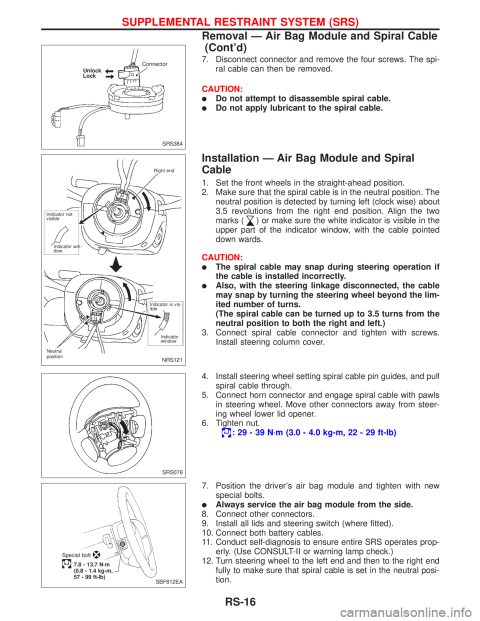
7. Disconnect connector and remove the four screws. The spi-
ral cable can then be removed.
CAUTION:
lDo not attempt to disassemble spiral cable.
lDo not apply lubricant to the spiral cable.
Installation Ð Air Bag Module and Spiral
Cable
1. Set the front wheels in the straight-ahead position.
2. Make sure that the spiral cable is in the neutral position. The
neutral position is detected by turning left (clock wise) about
3.5 revolutions from the right end position. Align the two
marks (
) or make sure the white indicator is visible in the
upper part of the indicator window, with the cable pointed
down wards.
CAUTION:
lThe spiral cable may snap during steering operation if
the cable is installed incorrectly.
lAlso, with the steering linkage disconnected, the cable
may snap by turning the steering wheel beyond the lim-
ited number of turns.
(The spiral cable can be turned up to 3.5 turns from the
neutral position to both the right and left.)
3. Connect spiral cable connector and tighten with screws.
Install steering column cover.
4. Install steering wheel setting spiral cable pin guides, and pull
spiral cable through.
5. Connect horn connector and engage spiral cable with pawls
in steering wheel. Move other connectors away from steer-
ing wheel lower lid opener.
6. Tighten nut.
: 29 - 39 N´m (3.0 - 4.0 kg-m, 22 - 29 ft-lb)
7. Position the driver's air bag module and tighten with new
special bolts.
lAlways service the air bag module from the side.
8. Connect other connectors.
9. Install all lids and steering switch (where fitted).
10. Connect both battery cables.
11. Conduct self-diagnosis to ensure entire SRS operates prop-
erly. (Use CONSULT-II or warning lamp check.)
12. Turn steering wheel to the left end and then to the right end
fully to make sure that spiral cable is set in the neutral posi-
tion.
SRS384 Unlock
LockConnector
NRS121
Neutral
positionRight end
Indicator not
visible
Indicator win-
dow
Indicator is vis-
ible
Indicator
window
SRS076
SBF812EA Special bolt
7.8 - 13.7 N´m
(0.8 - 1.4 kg-m,
57 - 99 ft-lb)
SUPPLEMENTAL RESTRAINT SYSTEM (SRS)
Removal Ð Air Bag Module and Spiral Cable
(Cont'd)
RS-16