1999 NISSAN PRIMERA check oil
[x] Cancel search: check oilPage 36 of 2267
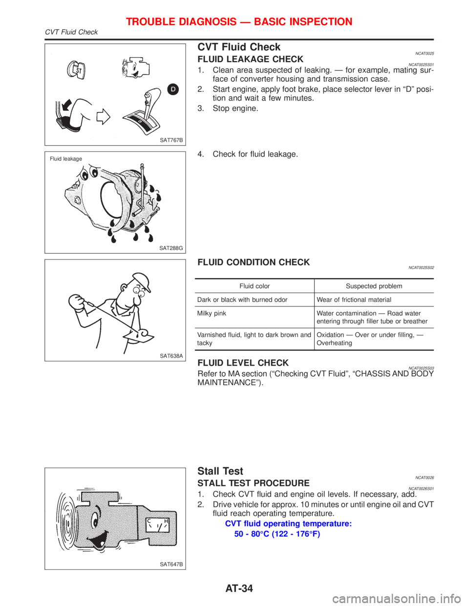
CVT Fluid CheckNCAT0025FLUID LEAKAGE CHECKNCAT0025S011. Clean area suspected of leaking. Ð for example, mating sur-
face of converter housing and transmission case.
2. Start engine, apply foot brake, place selector lever in ªDº posi-
tion and wait a few minutes.
3. Stop engine.
4. Check for fluid leakage.
FLUID CONDITION CHECKNCAT0025S02
Fluid color Suspected problem
Dark or black with burned odor Wear of frictional material
Milky pink Water contamination Ð Road water
entering through filler tube or breather
Varnished fluid, light to dark brown and
tackyOxidation Ð Over or under filling, Ð
Overheating
FLUID LEVEL CHECKNCAT0025S03Refer to MA section (ªChecking CVT Fluidº, ªCHASSIS AND BODY
MAINTENANCEº).
Stall TestNCAT0026STALL TEST PROCEDURENCAT0026S011. Check CVT fluid and engine oil levels. If necessary, add.
2. Drive vehicle for approx. 10 minutes or until engine oil and CVT
fluid reach operating temperature.
CVT fluid operating temperature:
50 - 80ÉC (122 - 176ÉF)
SAT767B
SAT288G Fluid leakage
SAT638A
SAT647B
TROUBLE DIAGNOSIS Ð BASIC INSPECTION
CVT Fluid Check
AT-34
Page 37 of 2267
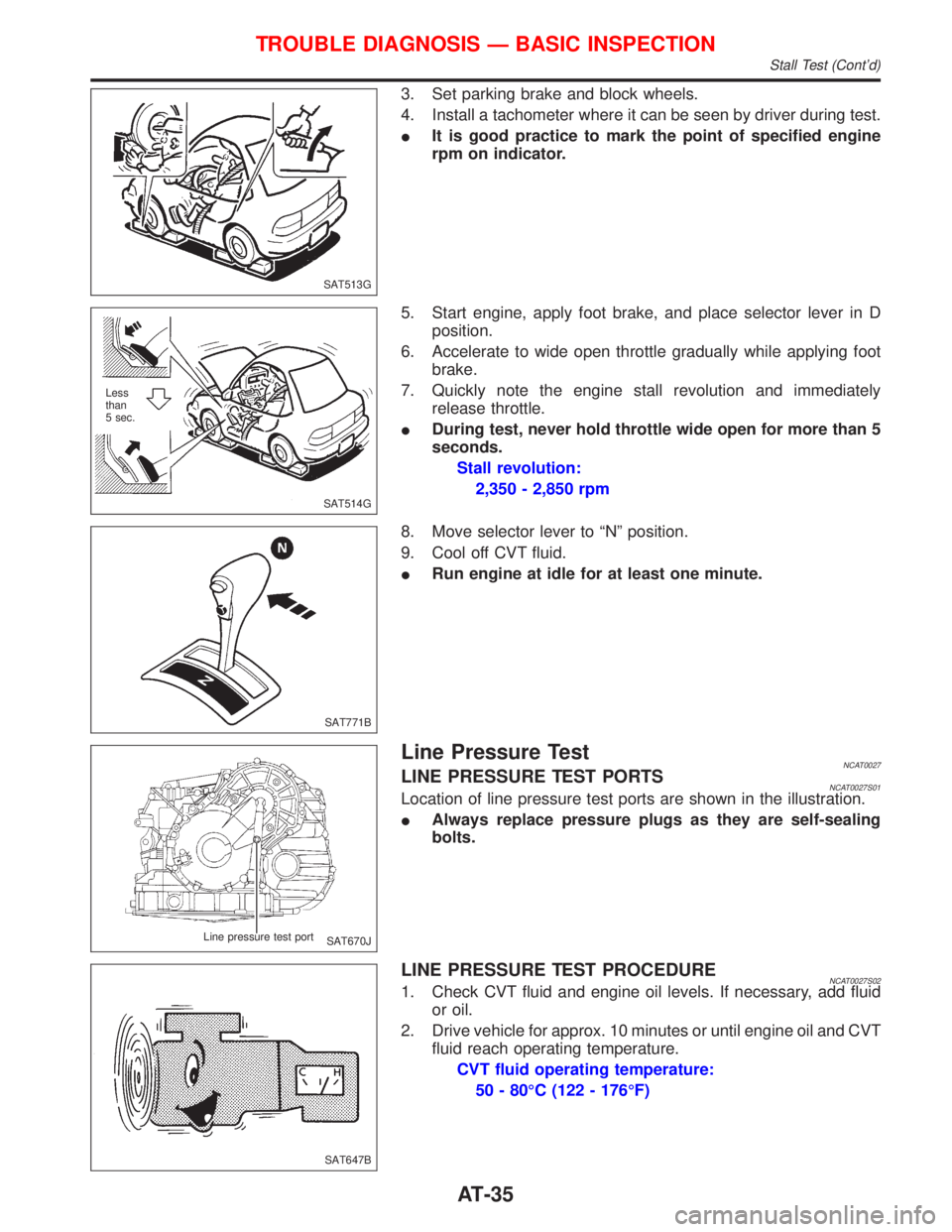
3. Set parking brake and block wheels.
4. Install a tachometer where it can be seen by driver during test.
IIt is good practice to mark the point of specified engine
rpm on indicator.
5. Start engine, apply foot brake, and place selector lever in D
position.
6. Accelerate to wide open throttle gradually while applying foot
brake.
7. Quickly note the engine stall revolution and immediately
release throttle.
IDuring test, never hold throttle wide open for more than 5
seconds.
Stall revolution:
2,350 - 2,850 rpm
8. Move selector lever to ªNº position.
9. Cool off CVT fluid.
IRun engine at idle for at least one minute.
Line Pressure TestNCAT0027LINE PRESSURE TEST PORTSNCAT0027S01Location of line pressure test ports are shown in the illustration.
IAlways replace pressure plugs as they are self-sealing
bolts.
LINE PRESSURE TEST PROCEDURENCAT0027S021. Check CVT fluid and engine oil levels. If necessary, add fluid
or oil.
2. Drive vehicle for approx. 10 minutes or until engine oil and CVT
fluid reach operating temperature.
CVT fluid operating temperature:
50 - 80ÉC (122 - 176ÉF)
SAT513G
SAT514G Less
than
5 sec.
SAT771B
SAT670J Line pressure test port
SAT647B
TROUBLE DIAGNOSIS Ð BASIC INSPECTION
Stall Test (Cont'd)
AT-35
Page 70 of 2267
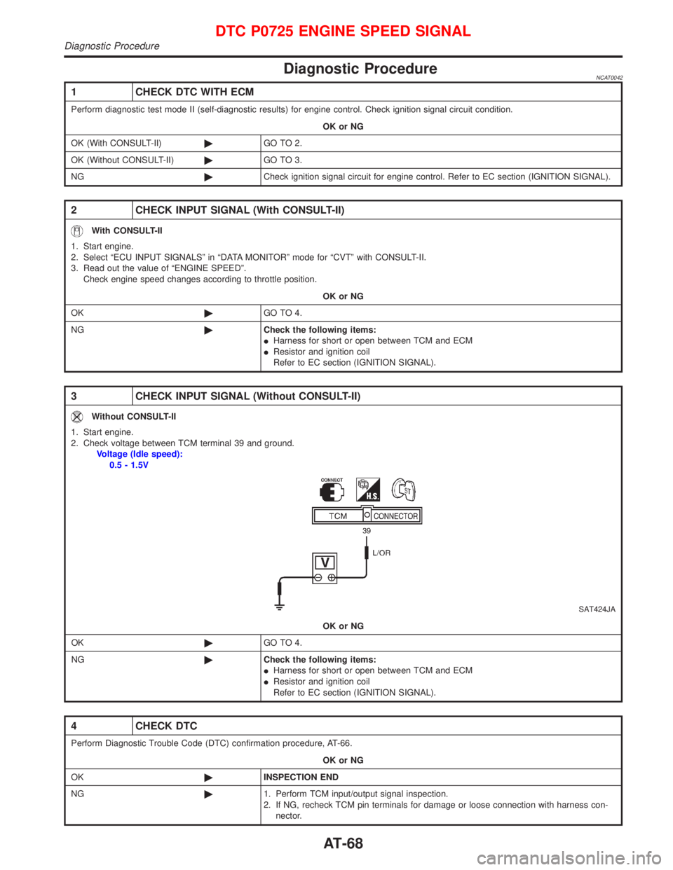
Diagnostic ProcedureNCAT0042
1 CHECK DTC WITH ECM
Perform diagnostic test mode II (self-diagnostic results) for engine control. Check ignition signal circuit condition.
OK or NG
OK (With CONSULT-II)©GO TO 2.
OK (Without CONSULT-II)©GO TO 3.
NG©Check ignition signal circuit for engine control. Refer to EC section (IGNITION SIGNAL).
2 CHECK INPUT SIGNAL (With CONSULT-II)
With CONSULT-II
1. Start engine.
2. Select ªECU INPUT SIGNALSº in ªDATA MONITORº mode for ªCVTº with CONSULT-II.
3. Read out the value of ªENGINE SPEEDº.
Check engine speed changes according to throttle position.
OK or NG
OK©GO TO 4.
NG©Check the following items:
IHarness for short or open between TCM and ECM
IResistor and ignition coil
Refer to EC section (IGNITION SIGNAL).
3 CHECK INPUT SIGNAL (Without CONSULT-II)
Without CONSULT-II
1. Start engine.
2. Check voltage between TCM terminal 39 and ground.
Voltage (Idle speed):
0.5 - 1.5V
SAT424JA
OK or NG
OK©GO TO 4.
NG©Check the following items:
IHarness for short or open between TCM and ECM
IResistor and ignition coil
Refer to EC section (IGNITION SIGNAL).
4 CHECK DTC
Perform Diagnostic Trouble Code (DTC) confirmation procedure, AT-66.
OK or NG
OK©INSPECTION END
NG©1. Perform TCM input/output signal inspection.
2. If NG, recheck TCM pin terminals for damage or loose connection with harness con-
nector.
DTC P0725 ENGINE SPEED SIGNAL
Diagnostic Procedure
AT-68
Page 76 of 2267
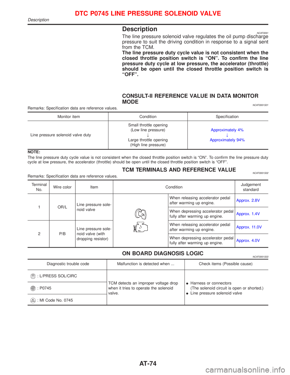
DescriptionNCAT0061The line pressure solenoid valve regulates the oil pump discharge
pressure to suit the driving condition in response to a signal sent
from the TCM.
The line pressure duty cycle value is not consistent when the
closed throttle position switch is ªONº. To confirm the line
pressure duty cycle at low pressure, the accelerator (throttle)
should be open until the closed throttle position switch is
ªOFFº.
CONSULT-II REFERENCE VALUE IN DATA MONITOR
MODE
NCAT0061S01Remarks: Specification data are reference values.
Monitor item Condition Specification
Line pressure solenoid valve dutySmall throttle opening
(Low line pressure)
"
Large throttle opening
(High line pressure)Approximately 4%
"
Approximately 94%
NOTE:
The line pressure duty cycle value is not consistent when the closed throttle position switch is ªONº. To confirm the line pressure duty
cycle at low pressure, the accelerator (throttle) should be open until the closed throttle position switch is ªOFFº.
TCM TERMINALS AND REFERENCE VALUENCAT0061S02Remarks: Specification data are reference values.
Terminal
No.Wire color Item ConditionJudgement
standard
1 OR/LLine pressure sole-
noid valve
When releasing accelerator pedal
after warming up engine.Approx. 2.8V
When depressing accelerator pedal
fully after warming up engine.Approx. 1.4V
2 P/BLine pressure sole-
noid valve (with
dropping resistor)When releasing accelerator pedal
after warming up engine.Approx. 11.0V
When depressing accelerator pedal
fully after warming up engine.Approx. 4.0V
ON BOARD DIAGNOSIS LOGICNCAT0061S03
Diagnostic trouble code Malfunction is detected when ... Check items (Possible cause)
: L/PRESS SOL/CIRC
TCM detects an improper voltage drop
when it tries to operate the solenoid
valve.IHarness or connectors
(The solenoid circuit is open or shorted.)
ILine pressure solenoid valve
: P0745
: MI Code No. 0745
DTC P0745 LINE PRESSURE SOLENOID VALVE
Description
AT-74
Page 116 of 2267
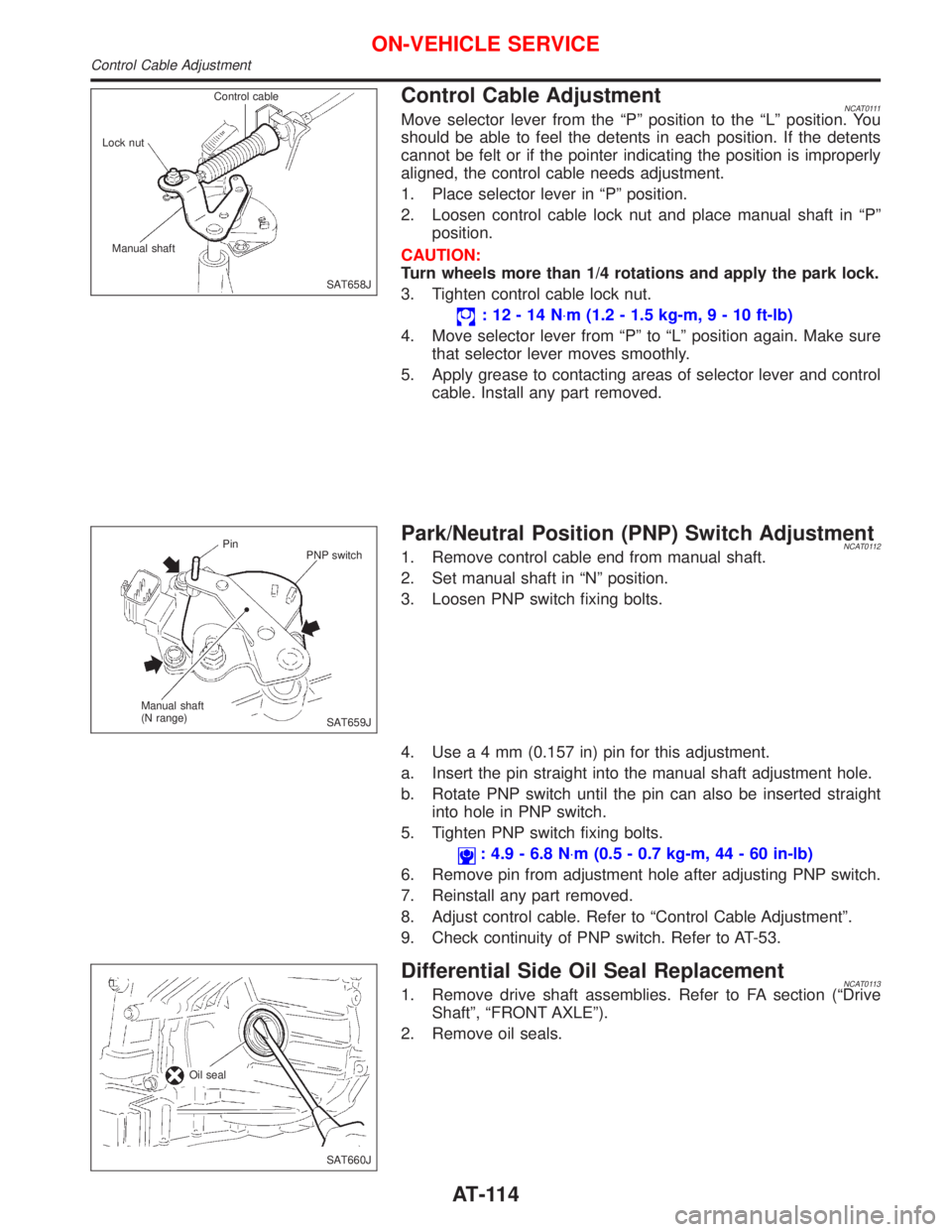
Control Cable AdjustmentNCAT0111Move selector lever from the ªPº position to the ªLº position. You
should be able to feel the detents in each position. If the detents
cannot be felt or if the pointer indicating the position is improperly
aligned, the control cable needs adjustment.
1. Place selector lever in ªPº position.
2. Loosen control cable lock nut and place manual shaft in ªPº
position.
CAUTION:
Turn wheels more than 1/4 rotations and apply the park lock.
3. Tighten control cable lock nut.
:12-14N×m (1.2 - 1.5 kg-m,9-10ft-lb)
4. Move selector lever from ªPº to ªLº position again. Make sure
that selector lever moves smoothly.
5. Apply grease to contacting areas of selector lever and control
cable. Install any part removed.
Park/Neutral Position (PNP) Switch AdjustmentNCAT01121. Remove control cable end from manual shaft.
2. Set manual shaft in ªNº position.
3. Loosen PNP switch fixing bolts.
4. Usea4mm(0.157 in) pin for this adjustment.
a. Insert the pin straight into the manual shaft adjustment hole.
b. Rotate PNP switch until the pin can also be inserted straight
into hole in PNP switch.
5. Tighten PNP switch fixing bolts.
: 4.9 - 6.8 N×m (0.5 - 0.7 kg-m, 44 - 60 in-lb)
6. Remove pin from adjustment hole after adjusting PNP switch.
7. Reinstall any part removed.
8. Adjust control cable. Refer to ªControl Cable Adjustmentº.
9. Check continuity of PNP switch. Refer to AT-53.
Differential Side Oil Seal ReplacementNCAT01131. Remove drive shaft assemblies. Refer to FA section (ªDrive
Shaftº, ªFRONT AXLEº).
2. Remove oil seals.
SAT658J Control cable
Lock nut
Manual shaft
SAT659J Pin
PNP switch
Manual shaft
(N range)
SAT660J Oil seal
ON-VEHICLE SERVICE
Control Cable Adjustment
AT-114
Page 125 of 2267
Supplemental Restraint System (SRS) ªAIR
BAGº and ªSEAT BELT PRE-TENSIONERº
The Supplemental Restraint System such as ªAIR BAGº and ªSEAT BELT PRE-TENSIONERº used along
with a seat belt, helps to reduce the risk or severity of injury to the driver and front passenger for certain
types of collision. The SRS system composition which is available to NISSAN MODEL P11 is as follows (The
composition varies according to the destination and optional equipment.):
lFor a frontal collision
The Supplemental Restraint System consists of driver air bag module (located in the center of the
steering wheel), front passenger air bag module (located on the instrument panel on passenger side),
front seat belt pre-tensioners, a diagnosis sensor unit, warning lamp, wiring harness and spiral cable.
lFor a side collision
The Supplemental Restraint System consists of front side air bag module (located in the outer side of
front seat), side air bag (satellite) sensor, diagnosis sensor unit (one of components of air bags for a
frontal collision), wiring harness, warning lamp (one of components of air bags for a frontal collision).
Information necessary to service the system safely is included in theRS sectionof this Service Manual.
WARNING:
lTo avoid rendering the SRS inoperative, which could increase the risk of personal injury or death
in the event of a collision which would result in air bag inflation, all maintenance should be per-
formed by an authorized NISSAN dealer.
lImproper maintenance, including incorrect removal and installation of the SRS, can lead to per-
sonal injury caused by unintentional activation of the system. For removal of Spiral Cable and
Air Bag Module, see the RS section.
lDo not use electrical test equipment on any circuit related to the SRS unless instructed to in this
Service Manual. Spiral cable and wiring harnesses covered with yellow insulation tape either just
before the harness connectors or for the complete harness are related to the SRS.
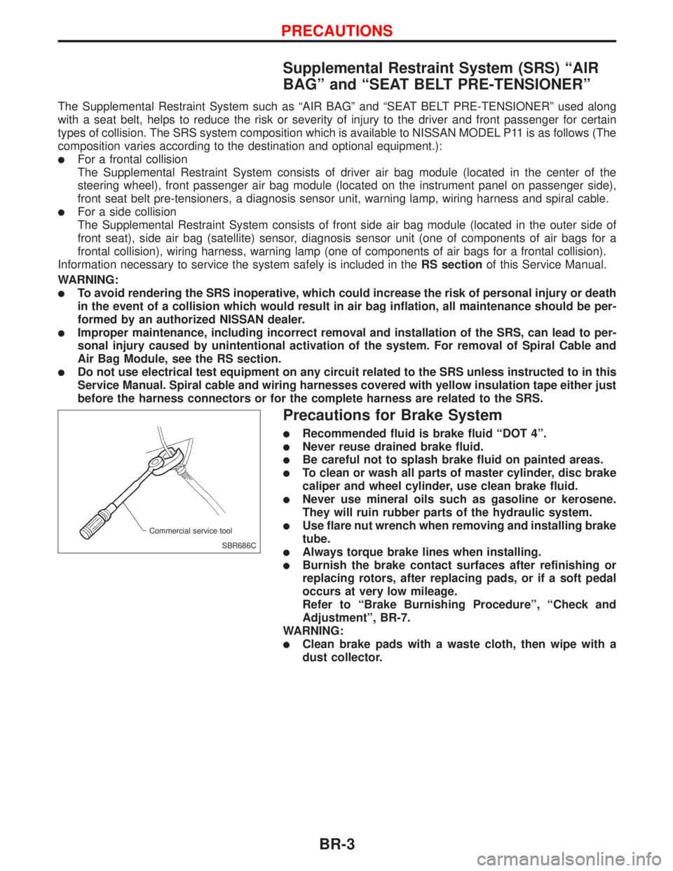
Precautions for Brake System
lRecommended fluid is brake fluid ªDOT 4º.
lNever reuse drained brake fluid.
lBe careful not to splash brake fluid on painted areas.
lTo clean or wash all parts of master cylinder, disc brake
caliper and wheel cylinder, use clean brake fluid.
lNever use mineral oils such as gasoline or kerosene.
They will ruin rubber parts of the hydraulic system.
lUse flare nut wrench when removing and installing brake
tube.
lAlways torque brake lines when installing.
lBurnish the brake contact surfaces after refinishing or
replacing rotors, after replacing pads, or if a soft pedal
occurs at very low mileage.
Refer to ªBrake Burnishing Procedureº, ªCheck and
Adjustmentº, BR-7.
WARNING:
lClean brake pads with a waste cloth, then wipe with a
dust collector.
SBR686C Commercial service tool
PRECAUTIONS
BR-3
Page 129 of 2267
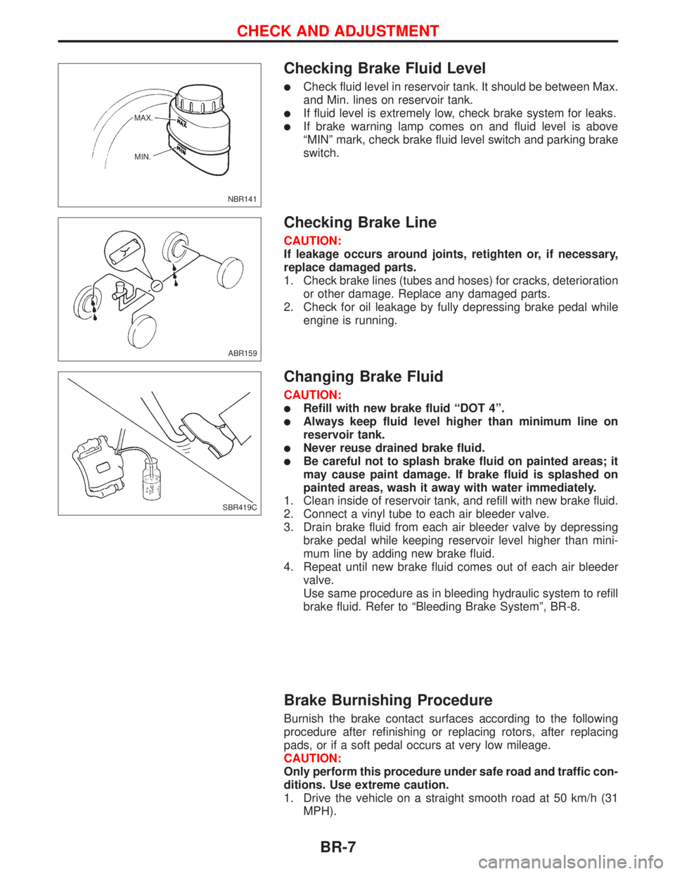
Checking Brake Fluid Level
lCheck fluid level in reservoir tank. It should be between Max.
and Min. lines on reservoir tank.
lIf fluid level is extremely low, check brake system for leaks.
lIf brake warning lamp comes on and fluid level is above
ªMINº mark, check brake fluid level switch and parking brake
switch.
Checking Brake Line
CAUTION:
If leakage occurs around joints, retighten or, if necessary,
replace damaged parts.
1. Check brake lines (tubes and hoses) for cracks, deterioration
or other damage. Replace any damaged parts.
2. Check for oil leakage by fully depressing brake pedal while
engine is running.
Changing Brake Fluid
CAUTION:
lRefill with new brake fluid ªDOT 4º.
lAlways keep fluid level higher than minimum line on
reservoir tank.
lNever reuse drained brake fluid.
lBe careful not to splash brake fluid on painted areas; it
may cause paint damage. If brake fluid is splashed on
painted areas, wash it away with water immediately.
1. Clean inside of reservoir tank, and refill with new brake fluid.
2. Connect a vinyl tube to each air bleeder valve.
3. Drain brake fluid from each air bleeder valve by depressing
brake pedal while keeping reservoir level higher than mini-
mum line by adding new brake fluid.
4. Repeat until new brake fluid comes out of each air bleeder
valve.
Use same procedure as in bleeding hydraulic system to refill
brake fluid. Refer to ªBleeding Brake Systemº, BR-8.
Brake Burnishing Procedure
Burnish the brake contact surfaces according to the following
procedure after refinishing or replacing rotors, after replacing
pads, or if a soft pedal occurs at very low mileage.
CAUTION:
Only perform this procedure under safe road and traffic con-
ditions. Use extreme caution.
1. Drive the vehicle on a straight smooth road at 50 km/h (31
MPH).
NBR141 MAX.
MIN.
ABR159
SBR419C
CHECK AND ADJUSTMENT
BR-7
Page 143 of 2267
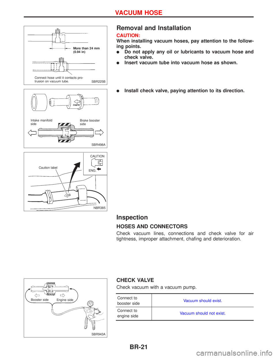
Removal and Installation
CAUTION:
When installing vacuum hoses, pay attention to the follow-
ing points.
lDo not apply any oil or lubricants to vacuum hose and
check valve.
lInsert vacuum tube into vacuum hose as shown.
lInstall check valve, paying attention to its direction.
Inspection
HOSES AND CONNECTORS
Check vacuum lines, connections and check valve for air
tightness, improper attachment, chafing and deterioration.
CHECK VALVE
Check vacuum with a vacuum pump.
Connect to
booster sideVacuum should exist.
Connect to
engine sideVacuum should not exist.
SBR225B More than 24 mm
(0.94 in)
Connect hose until it contacts pro-
trusion on vacuum tube.
SBR498A Intake manifold
sideBrake booster
side
NBR385 CAUTION
Caution label
ENG.
SBR943A Booster side
Engine side
VACUUM HOSE
BR-21