1999 NISSAN PRIMERA refrigerant type
[x] Cancel search: refrigerant typePage 1850 of 2267
HEATER &
AIR CONDITIONER
SECTION
HA
CONTENTS
PRECAUTIONS AND PREPARATION.......................... 3
Supplemental Restraint System (SRS)²AIR
BAG²and²SEAT BELT PRE-TENSIONER²............. 3
Precautions for Working with HFC-134a (R-134a) ... 3
General Refrigerant Precautions ............................... 4
Precautions for Refrigerant Connection .................... 4
Precautions for Servicing Compressor ...................... 7
Special Service Tools ................................................ 7
HFC-134a (R-134a) Service Tools and
Equipment .................................................................. 8
Precautions for Service Equipment ......................... 10
DESCRIPTION............................................................. 12
Refrigeration Cycle .................................................. 12
CSV613 Variable Displacement Compressor.......... 14
Component Layout .................................................. 18
HEATER
DESCRIPTION............................................................. 19
Control Operation .................................................... 19
Air Flow .................................................................... 19
AUTO
DESCRIPTION............................................................. 20
Introduction .............................................................. 20
Features ................................................................... 20
Control Operation .................................................... 21
Discharge Air Flow................................................... 23
HEATER
TROUBLE DIAGNOSES............................................. 24
Operational Check ................................................... 24
AUTO
TROUBLE DIAGNOSES............................................. 26
How to Perform Trouble Diagnoses for Quick
and Accurate Repair ................................................ 26
Symptom Chart ........................................................ 28
Checking Resistor.................................................... 30
Preliminary Check.................................................... 30
Performance Test Diagnoses .................................. 33
A/C Performance Chart ........................................... 35
Trouble Diagnoses for Abnormal Pressure ............. 36
Component Location................................................ 39
Wiring Diagram - HEATER -.................................... 40
Circuit Diagram - Air Conditioner............................. 41
Wiring Diagram - A/C - ............................................ 42
Main Power Supply and Ground Circuit Check ...... 51
Diagnostic Procedure 1 ........................................... 52
Diagnostic Procedure 2: Models with relay type 1.. 54
Diagnostic Procedure 2: Models with relay type 2.. 56
Diagnostic Procedure 3: Models with relay type 1.. 57
Diagnostic Procedure 3: Models with relay type 2.. 59
Diagnostic Procedure 4: Models with relay type 1.. 61
Diagnostic Procedure 4: Models with relay type 2.. 63
Diagnostic Procedure 5 ........................................... 65
Diagnostic Procedure 6 ........................................... 66
Diagnostic Procedure 7 ........................................... 68
Diagnostic Procedure 9 ........................................... 69
Diagnostic Procedure 10 ......................................... 70
Diagnostic Procedure 11 ......................................... 74
Diagnostic Procedure 12 ......................................... 75
Diagnostic Procedure 13 ......................................... 76
Diagnostic Procedure 14 ......................................... 77
Electrical Components Inspection ........................... 78
Control Panel System .............................................. 80
HA
Page 1852 of 2267
Supplemental Restraint System (SRS) ªAIR
BAGº and ªSEAT BELT PRE-TENSIONERº
The Supplemental Restraint System such as ªAIR BAGº and ªSEAT BELT PRE-TENSIONERº used along
with a seat belt, helps to reduce the risk or severity of injury to the driver and front passenger for certain
types of collision. The SRS system composition which is available to NISSAN MODEL P11 is as follows (The
composition varies according to optional equipment):
lFor a frontal collision
The Supplemental Restraint System consists of driver's air bag module (located in the center of the
steering wheel), front passenger's air bag module (located on the instrument panel on passenger's side),
seat belt pre-tensioners, a diagnosis sensor unit, warning lamp, wiring harness and spiral cable.
lFor a side collision
The Supplemental Restraint System consists of front side air bag module (located in the outer side of
front seat), satellite sensor, diagnosis sensor unit (one of components of air bags for a frontal collision),
wiring harness, warning lamp (one of components of air bags for a frontal collision).
Information necessary to service the system safely is included in theRS sectionof this Service Manual.
WARNING:
lTo avoid rendering the SRS inoperative, which could increase the risk of personal injury or death
in the event of a collision which would result in air bag inflation, all maintenance must be per-
formed by an authorized NISSAN dealer.
lImproper maintenance, including incorrect removal and installation of the SRS, can lead to per-
sonal injury caused by unintentional activation of the system. For removal of Spiral Cable and
Air Bag Module, see the RS section.
lDo not use electrical test equipment on any circuit related to the SRS unless instructed to in this
Service Manual. Spiral cable and wiring harnesses covered with yellow insulation or tape either
just before the harness connectors or for the complete harness are related to the SRS.
Precautions for Working with HFC-134a
(R-134a)
WARNING:
lCFC-12 (R-12) refrigerant and HFC-134a (R-134a) refrigerant are not compatible. These refriger-
ants must never be mixed, even in the smallest amounts. If the refrigerants are mixed, compres-
sor failure is likely to occur.
lUse only specified lubricant for the HFC-134a (R-134a) A/C system and HFC-134a (R-134a)
components. If lubricant other than that specified is used, compressor failure is likely to occur.
lThe specified HFC-134a (R-134a) lubricant rapidly absorbs moisture from the atmosphere. The
following handling precautions must be observed:
a: When removing refrigerant components from a vehicle, immediately cap (seal) the compo-
nent to minimize the entry of moisture from the atmosphere.
b: When installing refrigerant components to a vehicle, do not remove the caps (unseal) until
just before connecting the components. Connect all refrigerant loop components as quickly
as possible to minimize the entry of moisture into system.
c: Only use the specified lubricant from a sealed container. Immediately reseal containers of
lubricant. Without proper sealing, lubricant will become moisture saturated and should not
be used.
d: Avoid breathing A/C refrigerant and lubricant vapor or mist. Exposure may irritate eyes, nose
and throat. Remove R-134a from the A/C system, using certified service equipment meeting
requirements of SAE J2210 (R-134a recycling equipment), or J2209 (R-134a recovery equip-
ment). If accidental system discharge occurs, ventilate work area before resuming service.
Additional health and safety information may be obtained from refrigerant and lubricant
manufacturers.
e: Do not allow lubricant (Nissan A/C System Oil Type S or type R) to come in contact with sty-
rofoam parts. Damage may result.
PRECAUTIONS AND PREPARATION
HA-3
Page 1853 of 2267
General Refrigerant Precautions
WARNING:
lDo not release refrigerant into the air. Use approved recovery/recycling equipment to capture the
refrigerant every time an air conditioning system is discharged.
lAlways wear eye and hand protection (goggles and gloves) when working with any refrigerant or
air conditioning system.
lDo not store or heat refrigerant containers above 52ÉC (126ÉF).
lDo not heat a refrigerant container with an open flame; if container warming is required, place
the bottom of the container in a warm pail of water.
lDo not intentionally drop, puncture, or incinerate refrigerant containers.
lKeep refrigerant away from open flames: poisonous gas will be produced if refrigerant burns.
lRefrigerant will displace oxygen, therefore be certain to work in well ventilated areas to prevent
suffocation.
lDo not introduce compressed air to any refrigerant container or refrigerant component.
Precautions for Refrigerant Connection
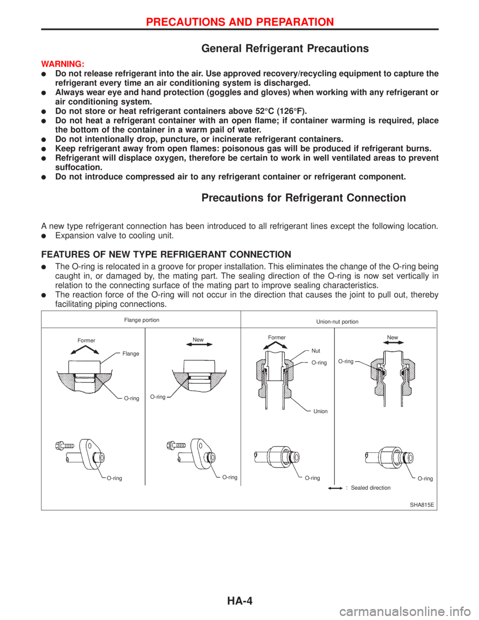
A new type refrigerant connection has been introduced to all refrigerant lines except the following location.
lExpansion valve to cooling unit.
FEATURES OF NEW TYPE REFRIGERANT CONNECTION
lThe O-ring is relocated in a groove for proper installation. This eliminates the change of the O-ring being
caught in, or damaged by, the mating part. The sealing direction of the O-ring is now set vertically in
relation to the connecting surface of the mating part to improve sealing characteristics.
lThe reaction force of the O-ring will not occur in the direction that causes the joint to pull out, thereby
facilitating piping connections.
SHA815E Flange portion
Union-nut portion
Former
Flange
O-ring
O-ringNew
O-ring
O-ringFormer
Nut
O-ring
O-ringO-ringNew
Sealed directionO-ring Union
PRECAUTIONS AND PREPARATION
HA-4
Page 1854 of 2267
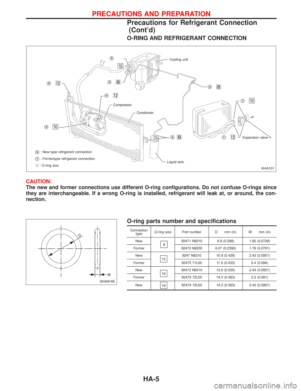
O-RING AND REFRIGERANT CONNECTION
CAUTION:
The new and former connections use different O-ring configurations. Do not confuse O-rings since
they are interchangeable. If a wrong O-ring is installed, refrigerant will leak at, or around, the con-
nection.
O-ring parts number and specifications
Connection
typeO-ring size Part number D mm (in) W mm (in)
New
892471 N8210 6.8 (0.268) 1.85 (0.0728)
Former 92470 N8200 6.07 (0.2390) 1.78 (0.0701)
New
129247 N8210 10.9 (0.429) 2.43 (0.0957)
Former 92475 71L00 11.0 (0.433) 2.4 (0.094)
New
1692473 N8210 13.6 (0.535) 2.43 (0.0957)
Former 92475 72L00 14.3 (0.563) 2.3 (0.091)
New
1992474 72L00 14.3 (0.563) 2.43 (0.0957)
KHA101
pN
pN
pN: New type refrigerant connection
pF: Formertype refrigerant connection
l: O-ring sizeLiquid tank
pNpFExpansion valve
pF
pN
Cooling unitpN
pN
pN
Compressor
Condenser
SHA814E
PRECAUTIONS AND PREPARATION
Precautions for Refrigerant Connection
(Cont'd)
HA-5
Page 1855 of 2267
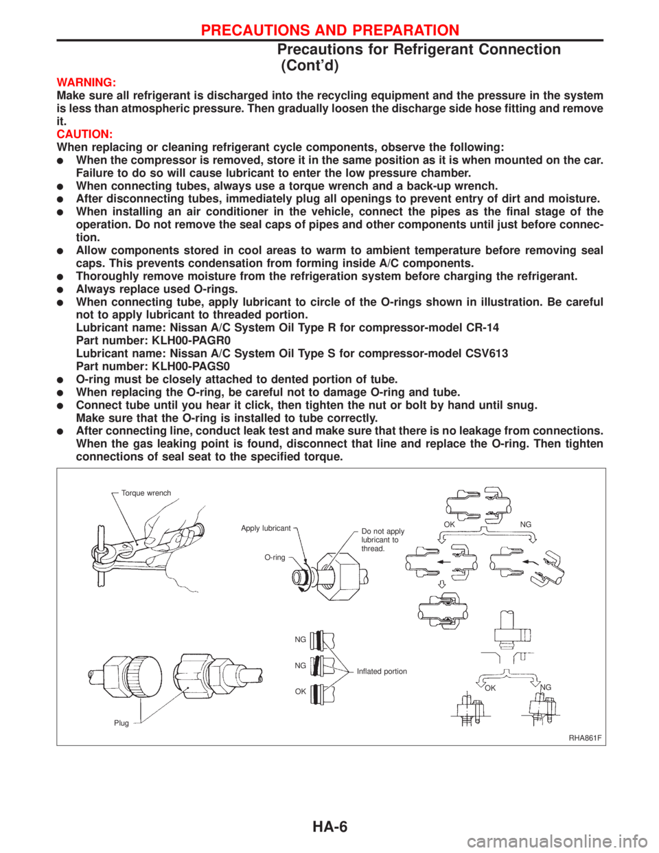
WARNING:
Make sure all refrigerant is discharged into the recycling equipment and the pressure in the system
is less than atmospheric pressure. Then gradually loosen the discharge side hose fitting and remove
it.
CAUTION:
When replacing or cleaning refrigerant cycle components, observe the following:
lWhen the compressor is removed, store it in the same position as it is when mounted on the car.
Failure to do so will cause lubricant to enter the low pressure chamber.
lWhen connecting tubes, always use a torque wrench and a back-up wrench.
lAfter disconnecting tubes, immediately plug all openings to prevent entry of dirt and moisture.
lWhen installing an air conditioner in the vehicle, connect the pipes as the final stage of the
operation. Do not remove the seal caps of pipes and other components until just before connec-
tion.
lAllow components stored in cool areas to warm to ambient temperature before removing seal
caps. This prevents condensation from forming inside A/C components.
lThoroughly remove moisture from the refrigeration system before charging the refrigerant.
lAlways replace used O-rings.
lWhen connecting tube, apply lubricant to circle of the O-rings shown in illustration. Be careful
not to apply lubricant to threaded portion.
Lubricant name: Nissan A/C System Oil Type R for compressor-model CR-14
Part number: KLH00-PAGR0
Lubricant name: Nissan A/C System Oil Type S for compressor-model CSV613
Part number: KLH00-PAGS0
lO-ring must be closely attached to dented portion of tube.
lWhen replacing the O-ring, be careful not to damage O-ring and tube.
lConnect tube until you hear it click, then tighten the nut or bolt by hand until snug.
Make sure that the O-ring is installed to tube correctly.
lAfter connecting line, conduct leak test and make sure that there is no leakage from connections.
When the gas leaking point is found, disconnect that line and replace the O-ring. Then tighten
connections of seal seat to the specified torque.
RHA861F Torque wrench
Apply lubricant
Do not apply
lubricant to
thread.NG OK
NG
OK Inflated portion NG
NG
OK
PlugO-ring
PRECAUTIONS AND PREPARATION
Precautions for Refrigerant Connection
(Cont'd)
HA-6
Page 1857 of 2267
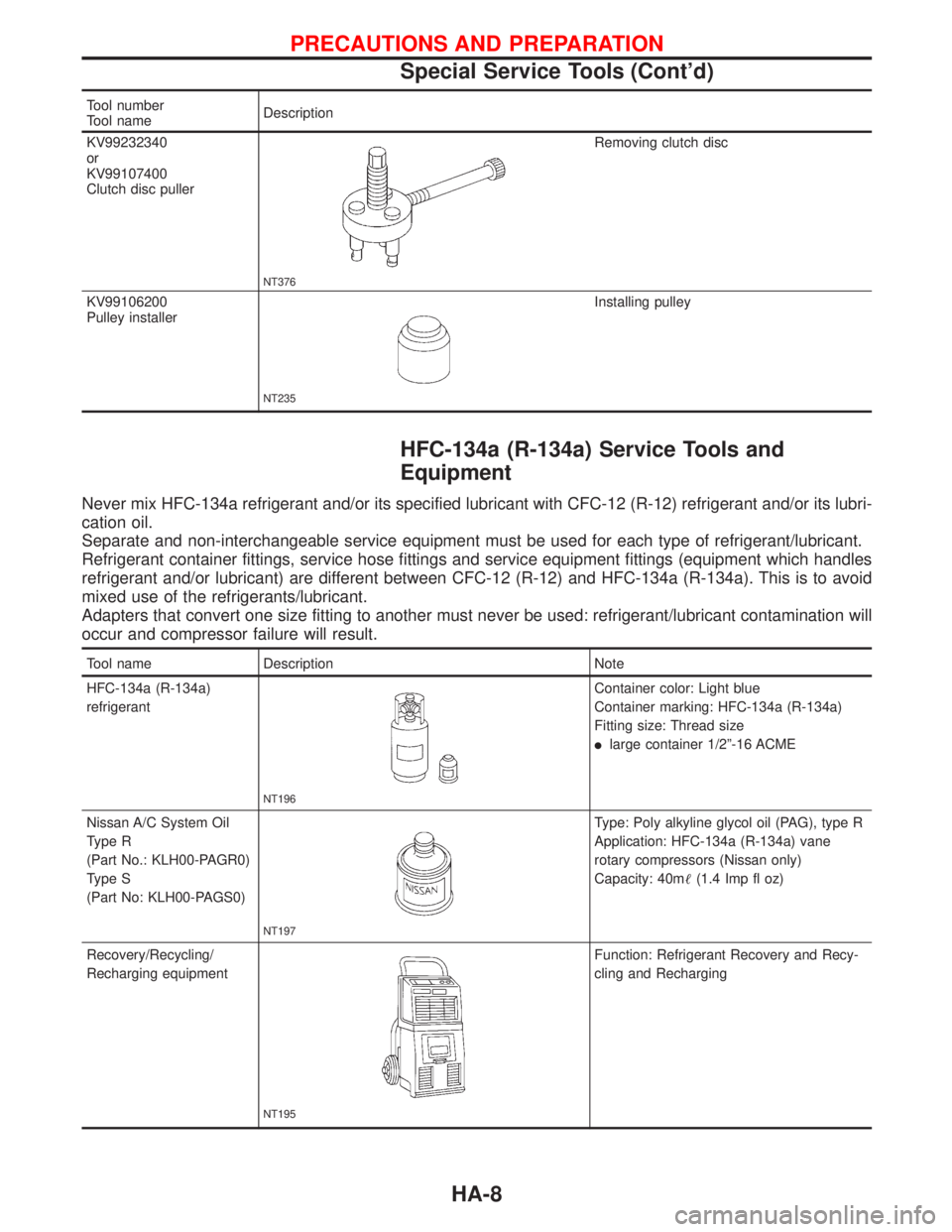
Tool number
Tool nameDescription
KV99232340
or
KV99107400
Clutch disc puller
NT376
Removing clutch disc
KV99106200
Pulley installer
NT235
Installing pulley
HFC-134a (R-134a) Service Tools and
Equipment
Never mix HFC-134a refrigerant and/or its specified lubricant with CFC-12 (R-12) refrigerant and/or its lubri-
cation oil.
Separate and non-interchangeable service equipment must be used for each type of refrigerant/lubricant.
Refrigerant container fittings, service hose fittings and service equipment fittings (equipment which handles
refrigerant and/or lubricant) are different between CFC-12 (R-12) and HFC-134a (R-134a). This is to avoid
mixed use of the refrigerants/lubricant.
Adapters that convert one size fitting to another must never be used: refrigerant/lubricant contamination will
occur and compressor failure will result.
Tool name Description Note
HFC-134a (R-134a)
refrigerant
NT196
Container color: Light blue
Container marking: HFC-134a (R-134a)
Fitting size: Thread size
llarge container 1/2º-16 ACME
Nissan A/C System Oil
Type R
(Part No.: KLH00-PAGR0)
Type S
(Part No: KLH00-PAGS0)
NT197
Type: Poly alkyline glycol oil (PAG), type R
Application: HFC-134a (R-134a) vane
rotary compressors (Nissan only)
Capacity: 40m(1.4 Imp fl oz)
Recovery/Recycling/
Recharging equipment
NT195
Function: Refrigerant Recovery and Recy-
cling and Recharging
PRECAUTIONS AND PREPARATION
Special Service Tools (Cont'd)
HA-8
Page 1864 of 2267
DESCRIPTION
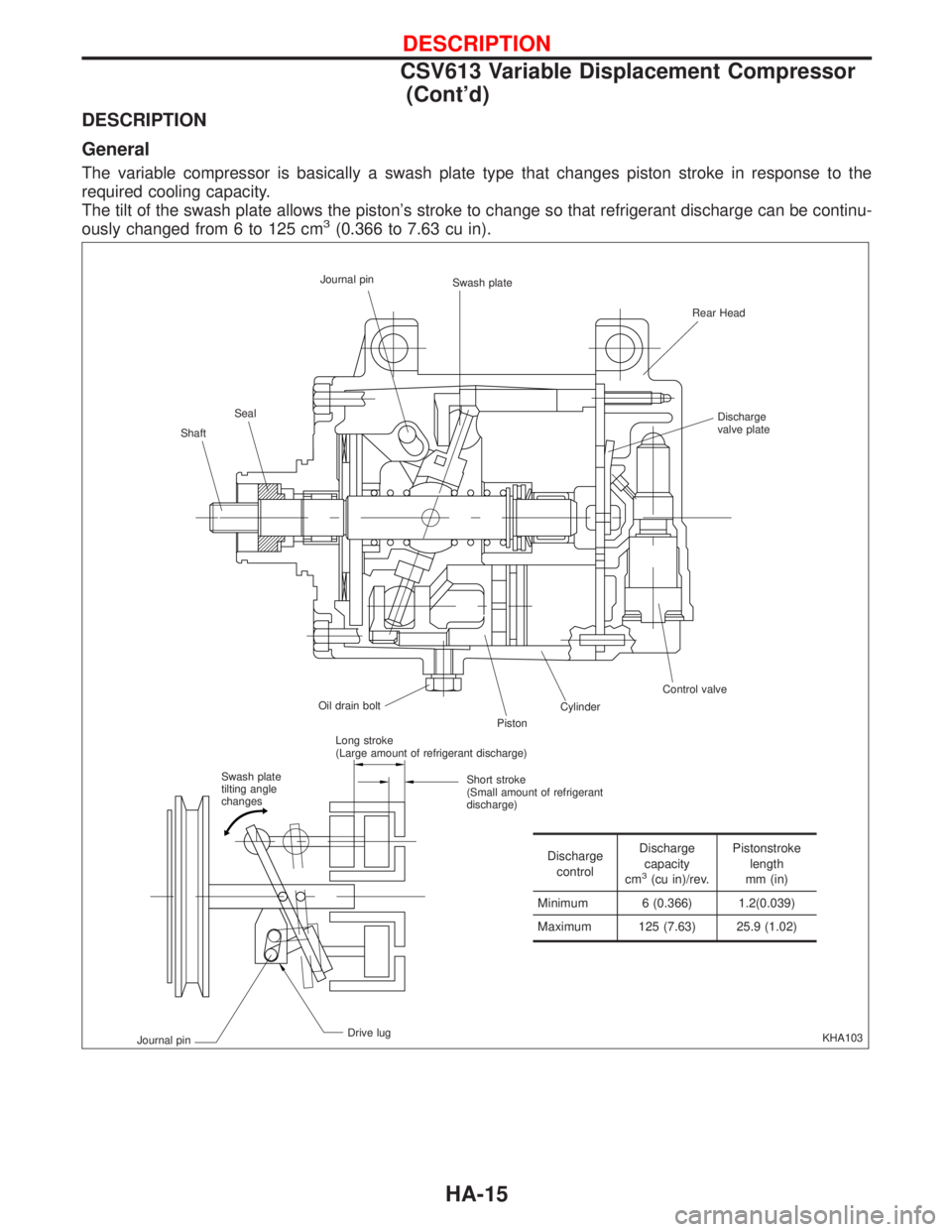
General
The variable compressor is basically a swash plate type that changes piston stroke in response to the
required cooling capacity.
The tilt of the swash plate allows the piston's stroke to change so that refrigerant discharge can be continu-
ously changed from 6 to 125 cm
3(0.366 to 7.63 cu in).
KHA103 ShaftSealJournal pin
Swash plate
Rear Head
Discharge
valve plate
Control valve
Cylinder
Piston Oil drain bolt
Swash plate
tilting angle
changesLong stroke
(Large amount of refrigerant discharge)
Short stroke
(Small amount of refrigerant
discharge)
Drive lug
Journal pin
Discharge
controlDischarge
capacity
cm
3(cu in)/rev.Pistonstroke
length
mm (in)
Minimum 6 (0.366) 1.2(0.039)
Maximum 125 (7.63) 25.9 (1.02)
DESCRIPTION
CSV613 Variable Displacement Compressor
(Cont'd)
HA-15
Page 1951 of 2267
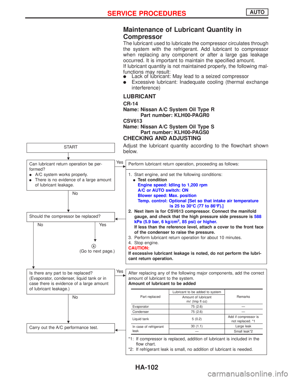
Maintenance of Lubricant Quantity in
Compressor
The lubricant used to lubricate the compressor circulates through
the system with the refrigerant. Add lubricant to compressor
when replacing any component or after a large gas leakage
occurred. It is important to maintain the specified amount.
If lubricant quantity is not maintained properly, the following mal-
functions may result:
lLack of lubricant: May lead to a seized compressor
lExcessive lubricant: Inadequate cooling (thermal exchange
interference)
LUBRICANT
CR-14
Name: Nissan A/C System Oil Type R
Part number: KLH00-PAGR0
CSV613
Name: Nissan A/C System Oil Type S
Part number: KLH00-PAGS0
CHECKING AND ADJUSTING
Adjust the lubricant quantity according to the flowchart shown
below.START
Can lubricant return operation be per-
formed?
lA/C system works properly.
lThere is no evidence of a large amount
of lubricant leakage.
No
EYe s
Perform lubricant return operation, proceeding as follows:
------------------------------------------------------------------------------------------------------------------------------------------------------------------------------------------------------------------------------------------------------------------------------------------------------------------------------------------------------------------------------------------------------------------------------------------------------------------------------------------------------------------------------------
1. Start engine, and set the following conditions:
lTest condition
Engine speed: Idling to 1,200 rpm
A/C or AUTO switch: ON
Blower speed: Max. position
Temp. control: Optional [Set so that intake air temperature
is 25 to 30ÉC (77 to 86ÉF).]
2. Next item is for CSV613 compressor. Connect the manifold
gauge, and check that the high pressure side pressure is588
kPa (5.9 bar, 6 kg/cm
2, 85 psi) or higher.
If less than the reference level, attach a cover to the front face
of the condenser to raise the pressure.
3. Perform lubricant return operation for about 10 minutes.
4. Stop engine.
CAUTION:
If excessive lubricant leakage is noted, do not perform the lubri-
cant return operation.
Should the compressor be replaced?
No Yes
F
pA
(Go to next page.)
Is there any part to be replaced?
(Evaporator, condenser, liquid tank or in
case there is evidence of a large amount
of lubricant leakage.)
No
EYe s
After replacing any of the following major components, add the correct
amount of lubricant to the system.
Amount of lubricant to be added
*1: If compressor is replaced, addition of lubricant is included in the
flow chart.
*2: If refrigerant leak is small, no addition of lubricant is needed.
Carry out the A/C performance test.F
Part replacedLubricant to be added to system
Remarks
Amount of lubricant
m(Imp fl oz)
Evaporator 75 (2.6) Ð
Condenser 75 (2.6) Ð
Liquid tank 5 (0.2)Add if compressor is
not replaced. *1
In case of refrigerant
leak30 (1.1) Large leak
Ð Small leak*2
H
H
H
H
H
SERVICE PROCEDURESAUTO
HA-102