1999 NISSAN PRIMERA spark plugs
[x] Cancel search: spark plugsPage 504 of 2267
![NISSAN PRIMERA 1999 Electronic Repair Manual DATA MONITOR (SPEC) MODENLEC1365S07
Monitored item [Unit]ECM
input
signalsMain
signalsDescription Remarks
MAS A/F SE-B1 [V]qqIThe signal voltage of the mass air flow sen-
sor specification is displaye NISSAN PRIMERA 1999 Electronic Repair Manual DATA MONITOR (SPEC) MODENLEC1365S07
Monitored item [Unit]ECM
input
signalsMain
signalsDescription Remarks
MAS A/F SE-B1 [V]qqIThe signal voltage of the mass air flow sen-
sor specification is displaye](/manual-img/5/57377/w960_57377-503.png)
DATA MONITOR (SPEC) MODENLEC1365S07
Monitored item [Unit]ECM
input
signalsMain
signalsDescription Remarks
MAS A/F SE-B1 [V]qqIThe signal voltage of the mass air flow sen-
sor specification is displayed.IWhen the engine is running, specifi-
cation range is indicated.
B/FUEL SCHDL
[msec]IªBase fuel scheduleº indicates the fuel injec-
tion pulse width programmed into ECM,
prior to any learned on board correction.IWhen the engine is running, specifi-
cation range is indicated.
A/F ALPHA-B1 [%]qIIndicates the mean value of the air-fuel ratio
feedback correction factor per cycle.IWhen the engine is running, specifi-
cation range is indicated.
IThis data also includes the data for
the air-fuel ratio learning control.
NOTE:
Any monitored item that does not match the vehicle being diagnosed is deleted from the display automatically.
ACTIVE TEST MODENCEC0034S07
TEST ITEM CONDITION JUDGEMENT CHECK ITEM (REMEDY)
FUEL INJECTIONIEngine: Return to the original
trouble condition
IChange the amount of fuel injec-
tion using CONSULT-II.If trouble symptom disappears, see
CHECK ITEM.IHarness and connector
IFuel injectors
IHeated oxygen sensor 1 (front)
IACV-AAC/V
OPENINGIEngine: After warming up, idle
the engine.
IChange the IACV-AAC valve
opening steps using CONSULT-
II.Engine speed changes according
to the opening steps.IHarness and connector
IIACV-AAC valve
ENG COOLANT
TEMPIEngine: Return to the original
trouble condition
IChange the engine coolant tem-
perature indication using CON-
SULT-II.If trouble symptom disappears, see
CHECK ITEM.IHarness and connector
IEngine coolant temperature sen-
sor
IFuel injectors
IGNITION TIMINGIEngine: Return to the original
trouble condition
ITiming light: Set
IRetard the ignition timing using
CONSULT-II.If trouble symptom disappears, see
CHECK ITEM.IªBase Idle Air Volume Initializingº
(Refer to EC-QG-33.)
ICamshaft position sensor
(PHASE)
ICrankshaft position sensor
(POS)
IEngine component parts and
installing conditions
POWER BAL-
ANCEIEngine: After warming up, idle
the engine.
IAir conditioner switch ªOFFº
IShift lever ªNº
ICut off each injector signal one
at a time using CONSULT-II.Engine runs rough or dies.IHarness and connector
ICompression
IInjectors
IPower transistor
ISpark plugs
IIgnition coils
COOLING FANIIgnition switch: ON
ITurn the cooling fan ªONº and
ªOFFº using CONSULT-II.Cooling fan moves and stops.IHarness and connector
ICooling fan motor
FUEL PUMP
RELAYIIgnition switch: ON
(Engine stopped)
ITurn the fuel pump relay ªONº
and ªOFFº using CONSULT-II
and listen to operating sound.Fuel pump relay makes the operat-
ing sound.IHarness and connector
IFuel pump relay
ON BOARD DIAGNOSTIC SYSTEM DESCRIPTIONQG16I18DE
CONSULT-II (Cont'd)
EC-62
Page 510 of 2267

IntroductionNCEC0036The engine has an ECM to control major systems such as fuel
control, ignition control, idle air control system, etc. The ECM
accepts input signals from sensors and instantly drives actuators.
It is essential that both input and output signals are proper and
stable. At the same time, it is important that there are no problems
such as vacuum leaks, fouled spark plugs, or other problems with
the engine.
It is much more difficult to diagnose a problem that occurs intermit-
tently rather than continuously. Most intermittent problems are
caused by poor electric connections or improper wiring. In this
case, careful checking of suspected circuits may help prevent the
replacement of good parts.
A visual check only may not find the cause of the problems. A road
test with CONSULT-II (or GST) or a circuit tester connected should
be performed. Follow the ªWork Flowº on EC-QG-70.
Before undertaking actual checks, take a few minutes to talk with
a customer who approaches with a driveability complaint. The cus-
tomer can supply good information about such problems, espe-
cially intermittent ones. Find out what symptoms are present and
under what conditions they occur. A ªDiagnostic Worksheetº like the
example on next page should be used.
Start your diagnosis by looking for ªconventionalº problems first.
This will help troubleshoot driveability problems on an electronically
controlled engine vehicle.
DIAGNOSTIC WORKSHEETNCEC0036S01There are many operating conditions that lead to the malfunction
of engine components. A good grasp of such conditions can make
trouble-shooting faster and more accurate.
In general, each customer feels differently about a problem. It is
important to fully understand the symptoms or conditions for a
customer complaint.
Utilize a diagnostic worksheet like the one on the next page in order
to organize all the information for troubleshooting.
Some conditions may cause the malfunction indicator to come on
steady or blink and DTC to be detected.
Example:
Vehicle ran out of fuel, which caused the engine to misfire.
MEF036D
SEF233G
SEF234G
SEF907L
KEY POINTS
WHAT îî..... Vehicle & engine
model
WHEN..... Date, Frequencies
WHERE..... Road conditions
HOW..... Operating conditions,
Weather conditions,
Symptoms
TROUBLE DIAGNOSIS Ð INTRODUCTIONQG16I18DE
Introduction
EC-68
Page 667 of 2267

6 CHECK IGNITION SPARK
1. Turn Ignition switch ªOFFº.
2. Disconnect ignition coil assembly from rocker cover.
3. Connect a known good spark plug to the ignition coil assembly.
4. Place end of spark plug against a suitable ground and crank engine.
5. Check for spark.
SEF575Q
OK or NG
OK©GO TO 7.
NG©Check ignition coil, power transistor and their circuits. Refer to EC-QG-323.
7 CHECK SPARK PLUGS
Remove the spark plugs and check for fouling, etc.
SEF156I
OK or NG
OK©GO TO 8.
NG©Repair or replace spark plug(s) with standard type one(s). For spark plug type, refer to
ªENGINE MAINTENANCEº in MA section.
8 CHECK COMPRESSION PRESSURE
Refer to EM section.
ICheck compression pressure.
Standard:
1,324 kPa (13.24 bar, 13.5 kg/cm
2, 192 psi)/350 rpm
Minimum:
1,128 kPa (11.28 bar, 11.5 kg/cm
2, 164 psi)/350 rpm
Difference between each cylinder:
98 kPa (0.98 bar, 1.0 kg/cm
2, 14 psi)/350 rpm
OK or NG
OK©GO TO 9.
NG©Check pistons, piston rings, valves, valve seats and cylinder head gaskets.
DTC P0300 - P0304 NO.4-1CYLINDER MISFIRE,
MULTIPLE CYLINDER MISFIREQG16I18DE
Diagnostic Procedure (Cont'd)
EC-225
Page 767 of 2267

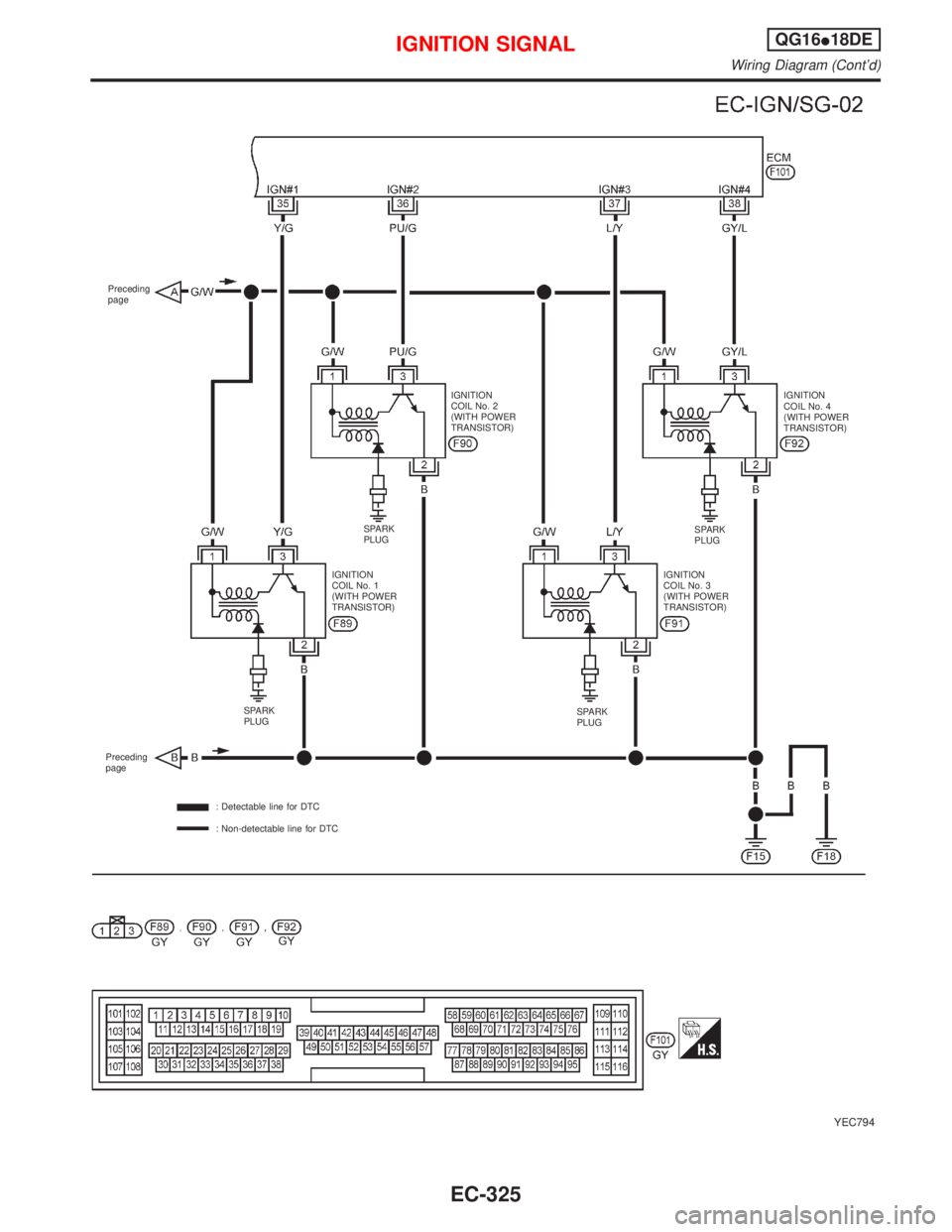
YEC794
Preceding
page
IGNITION
COIL No. 4
(WITH POWER
TRANSISTOR) IGNITION
COIL No. 2
(WITH POWER
TRANSISTOR)
SPARK
PLUG
IGNITION
COIL No. 1
(WITH POWER
TRANSISTOR)IGNITION
COIL No. 3
(WITH POWER
TRANSISTOR)SPARK
PLUG
SPARK
PLUGSPARK
PLUG
Preceding
page
: Detectable line for DTC
: Non-detectable line for DTC
IGNITION SIGNALQG16I18DE
Wiring Diagram (Cont'd)
EC-325
Page 875 of 2267

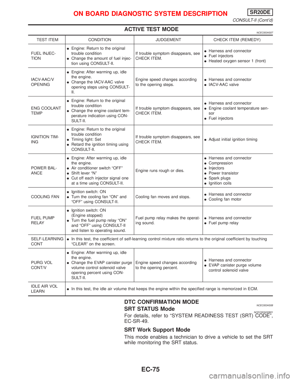
ACTIVE TEST MODENCEC0034S07
TEST ITEM CONDITION JUDGEMENT CHECK ITEM (REMEDY)
FUEL INJEC-
TIONIEngine: Return to the original
trouble condition
IChange the amount of fuel injec-
tion using CONSULT-II.If trouble symptom disappears, see
CHECK ITEM.IHarness and connector
IFuel injectors
IHeated oxygen sensor 1 (front)
IACV-AAC/V
OPENINGIEngine: After warming up, idle
the engine.
IChange the IACV-AAC valve
opening steps using CONSULT-
II.Engine speed changes according
to the opening steps.IHarness and connector
IIACV-AAC valve
ENG COOLANT
TEMPIEngine: Return to the original
trouble condition
IChange the engine coolant tem-
perature indication using CON-
SULT-II.If trouble symptom disappears, see
CHECK ITEM.IHarness and connector
IEngine coolant temperature sen-
sor
IFuel injectors
IGNITION TIM-
INGIEngine: Return to the original
trouble condition
ITiming light: Set
IRetard the ignition timing using
CONSULT-II.If trouble symptom disappears, see
CHECK ITEM.IAdjust initial ignition timing
POWER BAL-
ANCEIEngine: After warming up, idle
the engine.
IAir conditioner switch ªOFFº
IShift lever ªNº
ICut off each injector signal one
at a time using CONSULT-II.Engine runs rough or dies.IHarness and connector
ICompression
IInjectors
IPower transistor
ISpark plugs
IIgnition coils
COOLING FANIIgnition switch: ON
ITurn the cooling fan ªONº and
ªOFFº using CONSULT-II.Cooling fan moves and stops.IHarness and connector
ICooling fan motor
FUEL PUMP
RELAYIIgnition switch: ON
(Engine stopped)
ITurn the fuel pump relay ªONº
and ªOFFº using CONSULT-II
and listen to operating sound.Fuel pump relay makes the operat-
ing sound.IHarness and connector
IFuel pump relay
SELF-LEARNING
CONTIIn this test, the coefficient of self-learning control mixture ratio returns to the original coefficient by touching
ªCLEARº on the screen.
PURG VOL
CONT/VIEngine: After warming up, idle
the engine.
IChange the EVAP canister purge
volume control solenoid valve
opening percent using CON-
SULT-II.Engine speed changes according
to the opening percent.IHarness and connector
IEVAP canister purge volume
control solenoid valve
IDLE AIR VOL
LEARNIIn this test, the idle air volume that keeps the engine within the specified range is memorized in ECM.
DTC CONFIRMATION MODENCEC0034S08SRT STATUS ModeNCEC0034S0801For details, refer to ªSYSTEM READINESS TEST (SRT) CODEº,
EC-SR-49.
SRT Work Support Mode
This mode enables a technician to drive a vehicle to set the SRT
while monitoring the SRT status.
ON BOARD DIAGNOSTIC SYSTEM DESCRIPTIONSR20DE
CONSULT-II (Cont'd)
EC-75
Page 880 of 2267

IntroductionNCEC0036The engine has an ECM to control major systems such as fuel
control, ignition control, idle air control system, etc. The ECM
accepts input signals from sensors and instantly drives actuators.
It is essential that both input and output signals are proper and
stable. At the same time, it is important that there are no problems
such as vacuum leaks, fouled spark plugs, or other problems with
the engine.
It is much more difficult to diagnose a problem that occurs intermit-
tently rather than continuously. Most intermittent problems are
caused by poor electric connections or improper wiring. In this
case, careful checking of suspected circuits may help prevent the
replacement of good parts.
A visual check only may not find the cause of the problems. A road
test with CONSULT-II (or GST) or a circuit tester connected should
be performed. Follow the ªWork Flowº on EC-SR-82.
Before undertaking actual checks, take a few minutes to talk with
a customer who approaches with a driveability complaint. The cus-
tomer can supply good information about such problems, espe-
cially intermittent ones. Find out what symptoms are present and
under what conditions they occur. A ªDiagnostic Worksheetº like the
example on next page should be used.
Start your diagnosis by looking for ªconventionalº problems first.
This will help troubleshoot driveability problems on an electronically
controlled engine vehicle.
DIAGNOSTIC WORKSHEETNCEC0036S01There are many operating conditions that lead to the malfunction
of engine components. A good grasp of such conditions can make
trouble-shooting faster and more accurate.
In general, each customer feels differently about a problem. It is
important to fully understand the symptoms or conditions for a
customer complaint.
Utilize a diagnostic worksheet like the one on the next page in order
to organize all the information for troubleshooting.
Some conditions may cause the malfunction indicator to come on
steady or blink and DTC to be detected.
Example:
Vehicle ran out of fuel, which caused the engine to misfire.
MEF036D
SEF233G
SEF234G
SEF907L
KEY POINTS
WHAT..... Vehicle & engine model
WHEN..... Date, Frequencies
WHERE..... Road conditions
HOW..... Operating conditions,
Weather conditions,
Symptoms
TROUBLE DIAGNOSIS Ð INTRODUCTIONSR20DE
Introduction
EC-80
Page 1027 of 2267

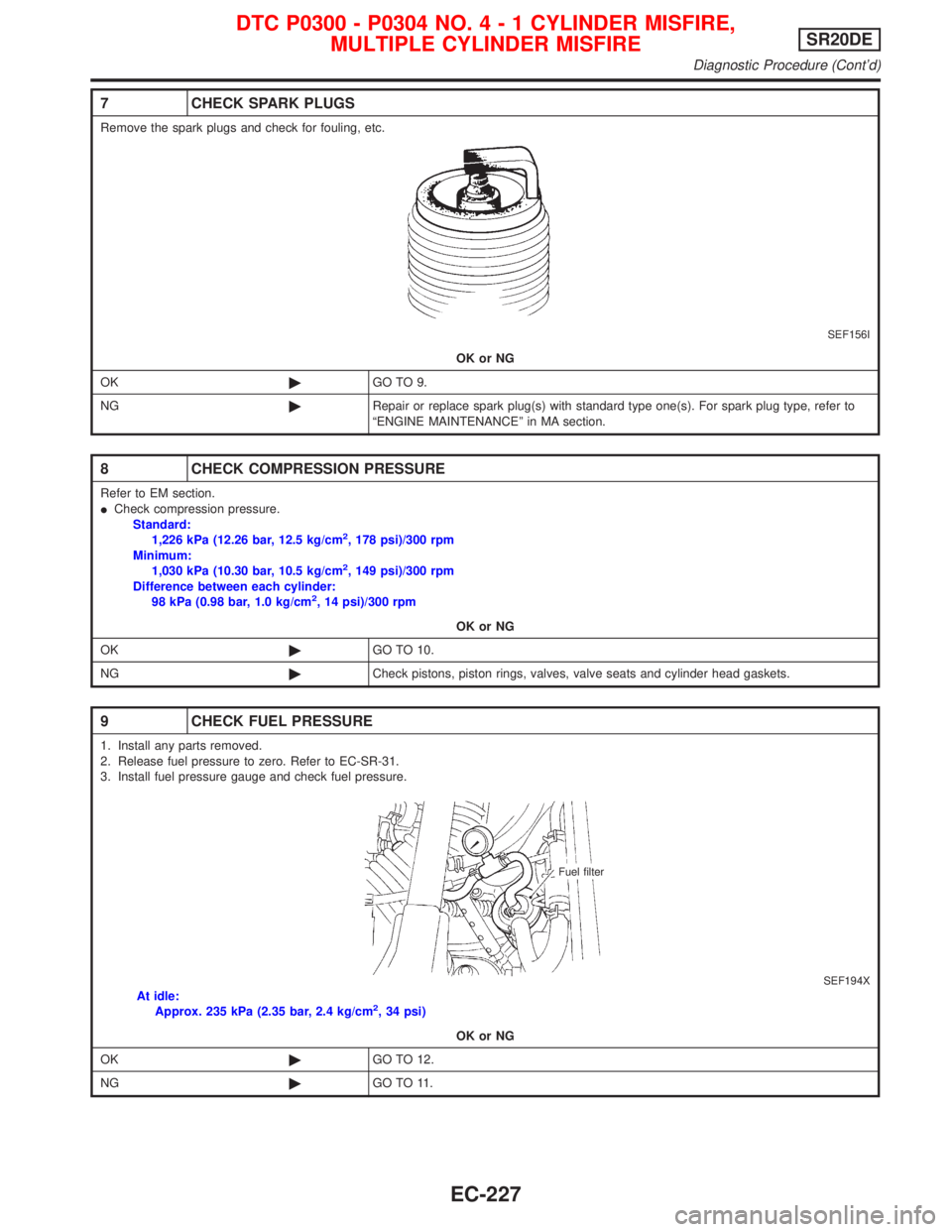
7 CHECK SPARK PLUGS
Remove the spark plugs and check for fouling, etc.
SEF156I
OK or NG
OK©GO TO 9.
NG©Repair or replace spark plug(s) with standard type one(s). For spark plug type, refer to
ªENGINE MAINTENANCEº in MA section.
8 CHECK COMPRESSION PRESSURE
Refer to EM section.
ICheck compression pressure.
Standard:
1,226 kPa (12.26 bar, 12.5 kg/cm
2, 178 psi)/300 rpm
Minimum:
1,030 kPa (10.30 bar, 10.5 kg/cm
2, 149 psi)/300 rpm
Difference between each cylinder:
98 kPa (0.98 bar, 1.0 kg/cm
2, 14 psi)/300 rpm
OK or NG
OK©GO TO 10.
NG©Check pistons, piston rings, valves, valve seats and cylinder head gaskets.
9 CHECK FUEL PRESSURE
1. Install any parts removed.
2. Release fuel pressure to zero. Refer to EC-SR-31.
3. Install fuel pressure gauge and check fuel pressure.
SEF194XAt idle:
Approx. 235 kPa (2.35 bar, 2.4 kg/cm2, 34 psi)
OK or NG
OK©GO TO 12.
NG©GO TO 11.
Fuel filter
DTC P0300 - P0304 NO.4-1CYLINDER MISFIRE,
MULTIPLE CYLINDER MISFIRESR20DE
Diagnostic Procedure (Cont'd)
EC-227
Page 1556 of 2267

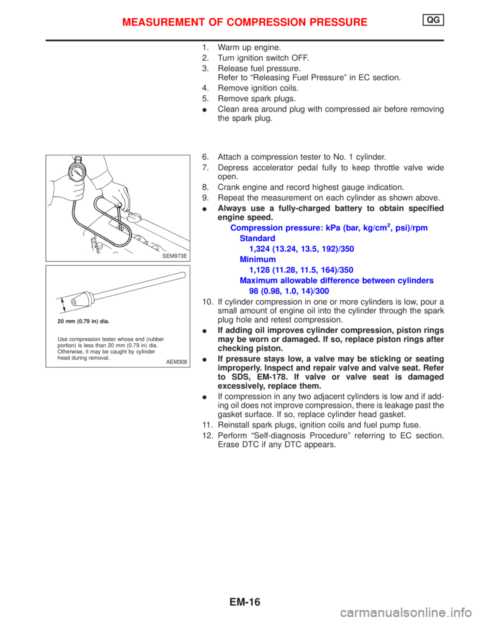
1. Warm up engine.
2. Turn ignition switch OFF.
3. Release fuel pressure.
Refer to ªReleasing Fuel Pressureº in EC section.
4. Remove ignition coils.
5. Remove spark plugs.
IClean area around plug with compressed air before removing
the spark plug.
6. Attach a compression tester to No. 1 cylinder.
7. Depress accelerator pedal fully to keep throttle valve wide
open.
8. Crank engine and record highest gauge indication.
9. Repeat the measurement on each cylinder as shown above.
IAlways use a fully-charged battery to obtain specified
engine speed.
Compression pressure: kPa (bar, kg/cm
2, psi)/rpm
Standard
1,324 (13.24, 13.5, 192)/350
Minimum
1,128 (11.28, 11.5, 164)/350
Maximum allowable difference between cylinders
98 (0.98, 1.0, 14)/300
10. If cylinder compression in one or more cylinders is low, pour a
small amount of engine oil into the cylinder through the spark
plug hole and retest compression.
IIf adding oil improves cylinder compression, piston rings
may be worn or damaged. If so, replace piston rings after
checking piston.
IIf pressure stays low, a valve may be sticking or seating
improperly. Inspect and repair valve and valve seat. Refer
to SDS, EM-178. If valve or valve seat is damaged
excessively, replace them.
IIf compression in any two adjacent cylinders is low and if add-
ing oil does not improve compression, there is leakage past the
gasket surface. If so, replace cylinder head gasket.
11. Reinstall spark plugs, ignition coils and fuel pump fuse.
12. Perform ªSelf-diagnosis Procedureº referring to EC section.
Erase DTC if any DTC appears.
SEM973E
AEM308 20 mm (0.79 in) dia.
Use compression tester whose end (rubber
portion) is less than 20 mm (0.79 in) dia.
Otherwise, it may be caught by cylinder
head during removal.
MEASUREMENT OF COMPRESSION PRESSUREQG
EM-16