Page 1560 of 2267
CAUTION:
IAfter removing timing chain, do not turn crankshaft and
camshaft separately, or valves will strike piston heads.
IWhen installing chain tensioner, oil seals, or other sliding
parts, lubricate contacting surfaces with new engine oil.
IApply new engine oil to bolt threads and seat surfaces
when installing camshaft sprocket and crankshaft pulley.
IWhen removing oil pump assembly, remove camshaft
position sensor (PHASE), then remove timing chain from
engine.
IBe careful not to damage sensor edges.
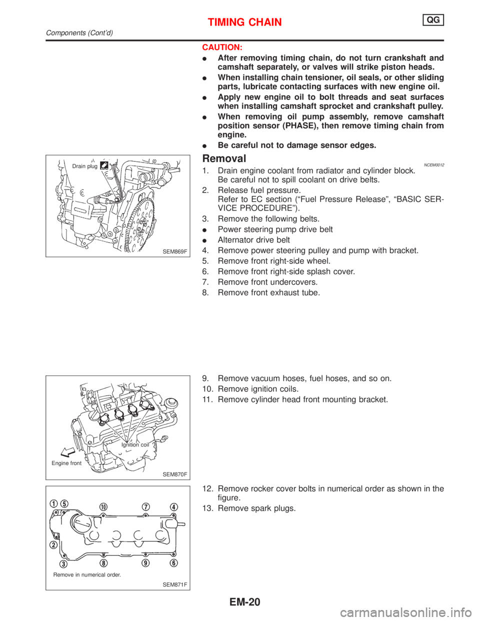
RemovalNCEM00121. Drain engine coolant from radiator and cylinder block.
Be careful not to spill coolant on drive belts.
2. Release fuel pressure.
Refer to EC section (ªFuel Pressure Releaseº, ªBASIC SER-
VICE PROCEDUREº).
3. Remove the following belts.
IPower steering pump drive belt
IAlternator drive belt
4. Remove power steering pulley and pump with bracket.
5. Remove front right-side wheel.
6. Remove front right-side splash cover.
7. Remove front undercovers.
8. Remove front exhaust tube.
9. Remove vacuum hoses, fuel hoses, and so on.
10. Remove ignition coils.
11. Remove cylinder head front mounting bracket.
12. Remove rocker cover bolts in numerical order as shown in the
figure.
13. Remove spark plugs.
SEM869F Drain plug
SEM870F Ignition coil
Engine front
SEM871F Remove in numerical order.
TIMING CHAINQG
Components (Cont'd)
EM-20
Page 1568 of 2267
27. Install rocker cover and tighten bolts in numerical order as
shown in the figure.
28. Install spark plugs.
29. Install ignition coils.
30. Install engine front mounting.
31. Install front exhaust tube.
32. Install front undercover.
33. Install front right splash cover.
34. Install front right wheel.
35. Install power steering pulley and pump with bracket.
To check power steering fluid, refer to MA section (ªChecking
Power Steering Fluid and Linesº, ªCHASSIS AND BODY
MAINTENANCEº).
36. Drive belts.
For adjusting drive belt deflection, refer to MA section (ªCheck-
ing Drive Beltsº, ªENGINE MAINTENANCEº).
37. Reinstall parts in reverse order of removal.
SEM908F Tighten in numerical order
TIMING CHAINQG
Installation (Cont'd)
EM-28
Page 1572 of 2267
CAUTION:
IWhen installing camshaft and oil seal, lubricate contacting
surfaces with new engine oil.
IWhen tightening cylinder head bolts, camshaft sprocket
bolts and camshaft bracket bolts, lubricate bolt threads
and seat surfaces with new engine oil.
IAttach tags to valve lifters so as not to mix them up.
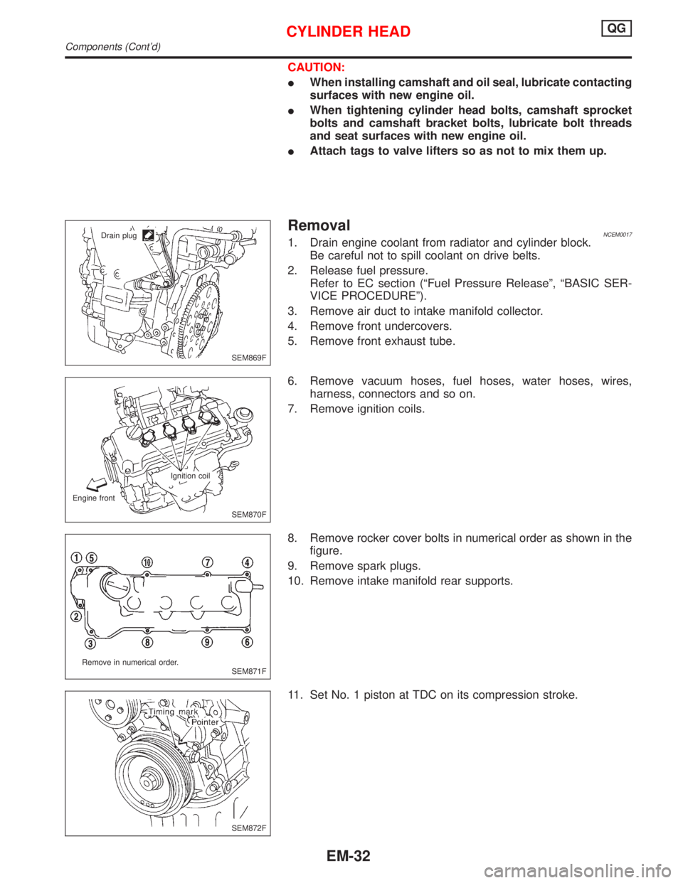
RemovalNCEM00171. Drain engine coolant from radiator and cylinder block.
Be careful not to spill coolant on drive belts.
2. Release fuel pressure.
Refer to EC section (ªFuel Pressure Releaseº, ªBASIC SER-
VICE PROCEDUREº).
3. Remove air duct to intake manifold collector.
4. Remove front undercovers.
5. Remove front exhaust tube.
6. Remove vacuum hoses, fuel hoses, water hoses, wires,
harness, connectors and so on.
7. Remove ignition coils.
8. Remove rocker cover bolts in numerical order as shown in the
figure.
9. Remove spark plugs.
10. Remove intake manifold rear supports.
11. Set No. 1 piston at TDC on its compression stroke.
SEM869F Drain plug
SEM870F Ignition coil
Engine front
SEM871F Remove in numerical order.
SEM872F
CYLINDER HEADQG
Components (Cont'd)
EM-32
Page 1580 of 2267
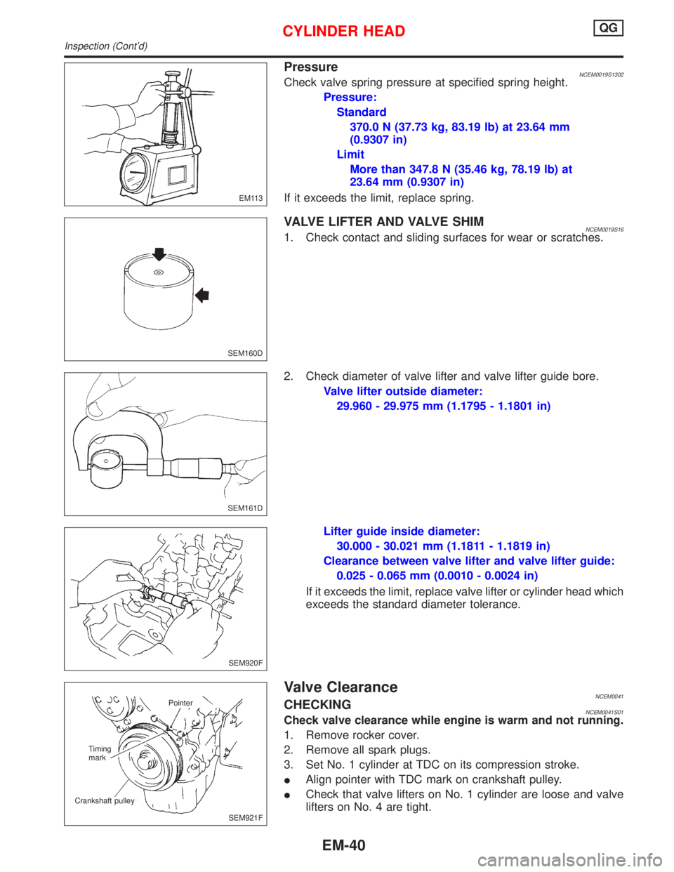
PressureNCEM0019S1302Check valve spring pressure at specified spring height.
Pressure:
Standard
370.0 N (37.73 kg, 83.19 lb) at 23.64 mm
(0.9307 in)
Limit
More than 347.8 N (35.46 kg, 78.19 lb) at
23.64 mm (0.9307 in)
If it exceeds the limit, replace spring.
VALVE LIFTER AND VALVE SHIMNCEM0019S161. Check contact and sliding surfaces for wear or scratches.
2. Check diameter of valve lifter and valve lifter guide bore.
Valve lifter outside diameter:
29.960 - 29.975 mm (1.1795 - 1.1801 in)
Lifter guide inside diameter:
30.000 - 30.021 mm (1.1811 - 1.1819 in)
Clearance between valve lifter and valve lifter guide:
0.025 - 0.065 mm (0.0010 - 0.0024 in)
If it exceeds the limit, replace valve lifter or cylinder head which
exceeds the standard diameter tolerance.
Valve ClearanceNCEM0041CHECKINGNCEM0041S01Check valve clearance while engine is warm and not running.
1. Remove rocker cover.
2. Remove all spark plugs.
3. Set No. 1 cylinder at TDC on its compression stroke.
IAlign pointer with TDC mark on crankshaft pulley.
ICheck that valve lifters on No. 1 cylinder are loose and valve
lifters on No. 4 are tight.
EM113
SEM160D
SEM161D
SEM920F
SEM921F Pointer
Timing
mark
Crankshaft pulley
CYLINDER HEADQG
Inspection (Cont'd)
EM-40
Page 1581 of 2267
IIf not, turn crankshaft one revolution (360É) and align as
described above.
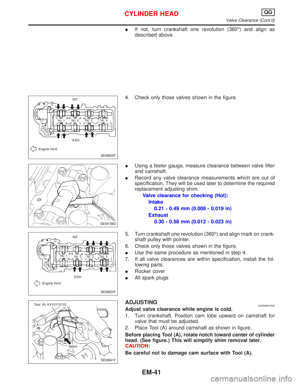
4. Check only those valves shown in the figure.
IUsing a feeler gauge, measure clearance between valve lifter
and camshaft.
IRecord any valve clearance measurements which are out of
specification. They will be used later to determine the required
replacement adjusting shim.
Valve clearance for checking (Hot):
Intake
0.21 - 0.49 mm (0.008 - 0.019 in)
Exhaust
0.30 - 0.58 mm (0.012 - 0.023 in)
5. Turn crankshaft one revolution (360É) and align mark on crank-
shaft pulley with pointer.
6. Check only those valves shown in the figure.
IUse the same procedure as mentioned in step 4.
7. If all valve clearances are within specification, install the fol-
lowing parts:
IRocker cover
IAll spark plugs
ADJUSTINGNCEM0041S02Adjust valve clearance while engine is cold.
1. Turn crankshaft. Position cam lobe upward on camshaft for
valve that must be adjusted.
2. Place Tool (A) around camshaft as shown in figure.
Before placing Tool (A), rotate notch toward center of cylinder
head. (See figure.) This will simplify shim removal later.
CAUTION:
Be careful not to damage cam surface with Tool (A).
SEM922F INT
EXH
Engine front
No. 4 No. 3 No. 2 No. 1
.SEM139D
SEM923F INT
EXH
Engine front
No. 1
No. 2
No. 3 No. 4
SEM941F Tool (A) KV10115110
Notch
CYLINDER HEADQG
Valve Clearance (Cont'd)
EM-41
Page 1586 of 2267
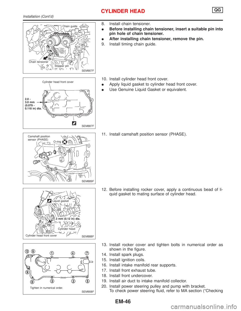
8. Install chain tensioner.
IBefore installing chain tensioner, insert a suitable pin into
pin hole of chain tensioner.
IAfter installing chain tensioner, remove the pin.
9. Install timing chain guide.
10. Install cylinder head front cover.
IApply liquid gasket to cylinder head front cover.
IUse Genuine Liquid Gasket or equivalent.
11. Install camshaft position sensor (PHASE).
12. Before installing rocker cover, apply a continuous bead of li-
quid gasket to mating surface of cylinder head.
13. Install rocker cover and tighten bolts in numerical order as
shown in the figure.
14. Install spark plugs.
15. Install ignition coils.
16. Install intake manifold rear supports.
17. Install front exhaust tube.
18. Install front undercover.
19. Install air duct to intake manifold collector.
20. Install power steering pulley and pump with bracket.
To check power steering fluid, refer to MA section (ªChecking
SEM907F Chain guide
Stopper pin Chain tensioner
SEM887F Cylinder head front cover
2.0 -
3.0 mm
(0.079 -
0.118 in) dia.
SEM889F Camshaft position
sensor (PHASE)
O-ring
SEM888F Liquid gasket
3 mm (0.12 in) dia.
Cylinder head
Cylinder head front cover
SEM908F Tighten in numerical order.
CYLINDER HEADQG
Installation (Cont'd)
EM-46
Page 1609 of 2267
Measurement of Compression Pressure
1. Warm up engine.
2. Turn ignition switch off.
3. Release fuel pressure.
Refer to ªReleasing Fuel Pressureº in EC-section.
4. Remove all spark plugs.
5. Disconnect distributor center cable.
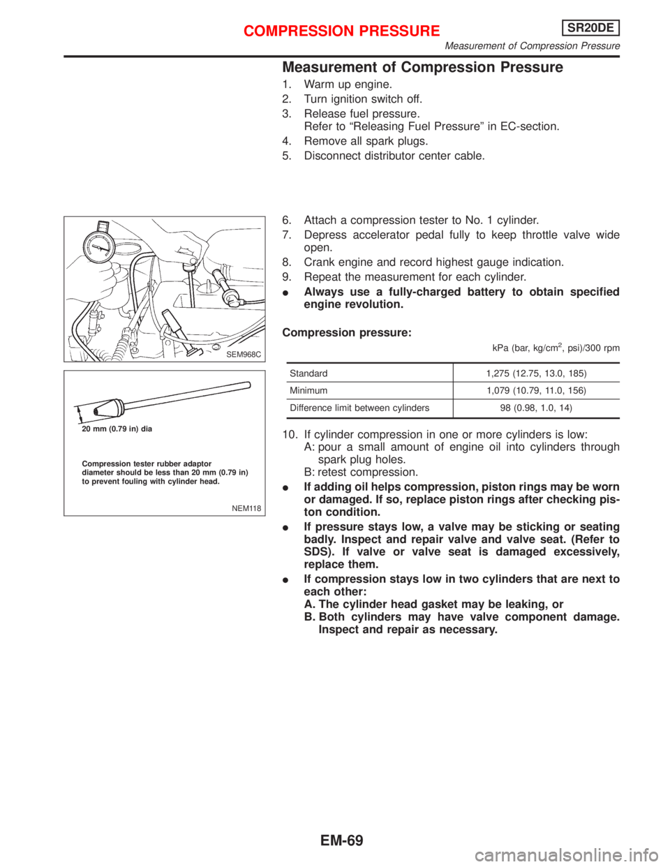
6. Attach a compression tester to No. 1 cylinder.
7. Depress accelerator pedal fully to keep throttle valve wide
open.
8. Crank engine and record highest gauge indication.
9. Repeat the measurement for each cylinder.
IAlways use a fully-charged battery to obtain specified
engine revolution.
Compression pressure:
kPa (bar, kg/cm2, psi)/300 rpm
Standard 1,275 (12.75, 13.0, 185)
Minimum 1,079 (10.79, 11.0, 156)
Difference limit between cylinders 98 (0.98, 1.0, 14)
10. If cylinder compression in one or more cylinders is low:
A: pour a small amount of engine oil into cylinders through
spark plug holes.
B: retest compression.
IIf adding oil helps compression, piston rings may be worn
or damaged. If so, replace piston rings after checking pis-
ton condition.
IIf pressure stays low, a valve may be sticking or seating
badly. Inspect and repair valve and valve seat. (Refer to
SDS). If valve or valve seat is damaged excessively,
replace them.
IIf compression stays low in two cylinders that are next to
each other:
A. The cylinder head gasket may be leaking, or
B. Both cylinders may have valve component damage.
Inspect and repair as necessary.
SEM968C
NEM118 20 mm (0.79 in) dia
Compression tester rubber adaptor
diameter should be less than 20 mm (0.79 in)
to prevent fouling with cylinder head.
COMPRESSION PRESSURESR20DE
Measurement of Compression Pressure
EM-69
Page 1623 of 2267
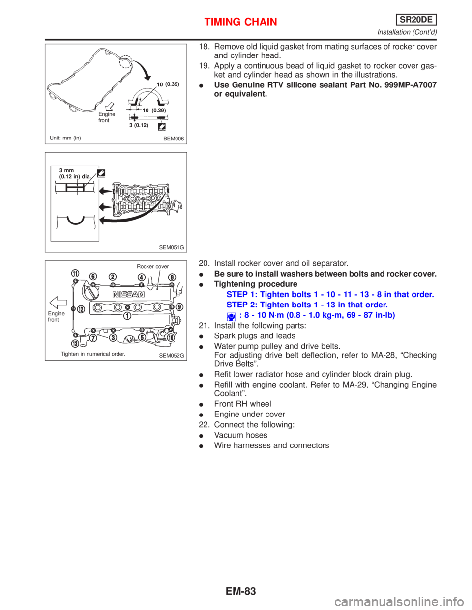
18. Remove old liquid gasket from mating surfaces of rocker cover
and cylinder head.
19. Apply a continuous bead of liquid gasket to rocker cover gas-
ket and cylinder head as shown in the illustrations.
IUse Genuine RTV silicone sealant Part No. 999MP-A7007
or equivalent.
20. Install rocker cover and oil separator.
IBe sure to install washers between bolts and rocker cover.
ITightening procedure
STEP 1: Tighten bolts1-10-11-13-8inthat order.
STEP 2: Tighten bolts1-13inthat order.
:8-10N×m (0.8 - 1.0 kg-m, 69 - 87 in-lb)
21. Install the following parts:
ISpark plugs and leads
IWater pump pulley and drive belts.
For adjusting drive belt deflection, refer to MA-28, ªChecking
Drive Beltsº.
IRefit lower radiator hose and cylinder block drain plug.
IRefill with engine coolant. Refer to MA-29, ªChanging Engine
Coolantº.
IFront RH wheel
IEngine under cover
22. Connect the following:
IVacuum hoses
IWire harnesses and connectors
BEM006 Engine
front
Unit: mm (in)3 (0.12)(0.39)
(0.39)
SEM051G 3mm
(0.12 in) dia.
SEM052G Engine
front
Tighten in numerical order.Rocker cover
TIMING CHAINSR20DE
Installation (Cont'd)
EM-83