Page 1 of 2267
Edition:May 2001
GENERA LINFORMATIONGI
MAINTENANCEMA
ENGIN EMECHANICALEM
ENGIN ELUBRICATIO N&LC
ENGIN ECONTRO LSYSTEMQG16/18DE
ENGIN ECONTRO LSYSTEMSR20DE
ENGIN ECONTRO LSYSTEMCD20T
ACCELERATO RCONTROL,FE
CLUTCHCL
MANUA LTRANSAXLEMT
AUTOMATI CTRANSAXLEAT
FRON TAXL E& FRON TSUSPENSIONFA
REA RAXL E& REA RSUSPENSIONRA
BRAK ESYSTEMBR
STEERIN GSYSTEMST
RESTRAIN TSYSTEMRS
BOD Y& TRIMBT
HEATE R&AIR CONDITIONERHA
ELECTRICA LSYSTEMEL
ALPHABETICA LINDEXIDX
PRIMERA
NISSA NEUROP EN.V.
Page 128 of 2267
NVH Troubleshooting Chart
Use the chart to help you find the cause of the symptom. If necessary, repair or replace these parts.
Reference page
BR-23, 26, 33
BR-23 26, 33
BR-23, 33
Ð
BR-31, 37, 43
BR-31, 37, 43
Ð
Ð
Ð
BR-31, 37
NHV in PD section
NHV in PD section
NHV in FA, RA section
NHV in FA section
NHV in FA section
NHV in FA section
NHV in ST section
Possible cause and
SUSPECTED PARTS
Pads - damaged
Pads - uneven wear
Shims damaged
Rotor imbalance
Rotor damaged
Rotor runout
Rotor deformation
Rotor deflection
Rotor rust
Rotor thickness variation
PROPELLER SHAFT
DIFFERENTIAL
AXLE AND SUSPENSION
TIRES
ROAD WHEEL
AXLE SHAFT
STEERING
Symptom BRAKENoise x x xxxxxxxx
Shake x xxxxxx
Shimmy, Judderxxxxxxx xxx x
X : Applicable
NOISE, VIBRATION AND HARSHNESS (NVH) TROUBLE SHOOTING
BR-6
Page 275 of 2267
MEASUREMENT POINTS
Unit: mm
YBT039 Front
Cowl top
YBT041
.Front suspension spring support and cowl top side
.YBT043
Front side member RH side
Front
YBT045
Radiator core support upper center and
hood lock stay
YBT040
Radiator core support side and Radiator
core support
7 dia.
6.2 dia.
7 dia.
YBT042 Front
Front side member LH side
YBT044
Hood lock stay and Radiator core support lower
BODY ALIGNMENT
Engine Compartment (Cont'd)
BT-61
Page 1223 of 2267

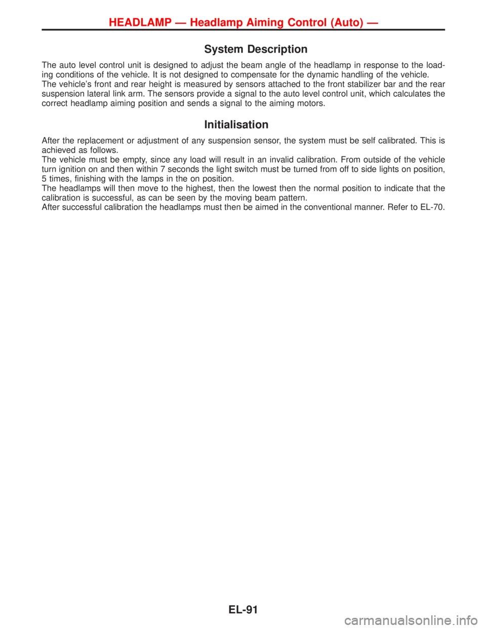
System Description
The auto level control unit is designed to adjust the beam angle of the headlamp in response to the load-
ing conditions of the vehicle. It is not designed to compensate for the dynamic handling of the vehicle.
The vehicle’s front and rear height is measured by sensors attached to the front stabilizer bar and the rear
suspension lateral link arm. The sensors provide a signal to the auto level control unit, which calculates the
correct headlamp aiming position and sends a signal to the aiming motors.
Initialisation
After the replacement or adjustment of any suspension sensor, the system must be self calibrated. This is
achieved as follows.
The vehicle must be empty, since any load will result in an invalid calibration. From outside of the vehicle
turn ignition on and then within 7 seconds the light switch must be turned from off to side lights on position,
5 times, finishing with the lamps in the on position.
The headlamps will then move to the highest, then the lowest then the normal position to indicate that the
calibration is successful, as can be seen by the moving beam pattern.
After successful calibration the headlamps must then be aimed in the conventional manner. Refer to EL-70.
HEADLAMP—Headlamp Aiming Control (Auto)—
EL-91
Page 1231 of 2267
Removal and Installation
Front sensor
YEL621B
4.0 - 5.0 (0.4 - 0.51, 35 - 44)
Front linkage to be clamped onto
stabilizer bar with wheels down
and suspension settled. Rotation
to be fixed with link arm in hori-
zontal plane.
18 mm (0.71 in)
3.3 - 7.7 (0.33 - 0.79, 29 - 68)
Rear sensor
3.3 - 7.7 (0.33 - 0.79, 29 - 68)
:N·m (kg-m, in-lb)3.3 - 7.7 (0.33 - 0.79, 29 - 68)The rear sensor linkage does not
require setting, but with the wheel on
the ground and the suspension
settled, ensure that the link arm in the
same plane as the connector wire.
HEADLAMP—Headlamp Aiming Control (Auto)—
EL-99
Page 1743 of 2267

FRONT AXLE &
FRONT SUSPENSION
SECTION
FA
CONTENTS
PRECAUTIONS AND PREPARATION.......................... 2
Precautions ................................................................ 2
Special Service Tools ................................................ 2
NOISE, VIBRATION AND HARSHNESS (NVH)
TROUBLESHOOTING................................................... 3
NVH Troubleshooting Chart....................................... 3
FRONT SUSPENSION SYSTEM.................................. 4
ON-VEHICLE SERVICE................................................ 5
Front Axle and Front Suspension Parts .................... 5
Front Wheel Bearing.................................................. 6
Front Wheel Alignment .............................................. 6
Drive Shaft ................................................................. 8FRONT AXLE................................................................ 9
Wheel Hub and Knuckle ........................................... 11
Drive shaft................................................................ 15
FRONT SUSPENSION................................................ 26
Coil Spring and Shock Absorber ............................. 28
Third Link and Upper Link ....................................... 29
Transverse Link and Lower Ball Joint ..................... 32
Stabilizer Bar ........................................................... 32
SERVICE DATA AND SPECIFICATIONS (SDS)........ 34
General Specifications ............................................. 34
Inspection and Adjustment ...................................... 35
FA
Page 1744 of 2267

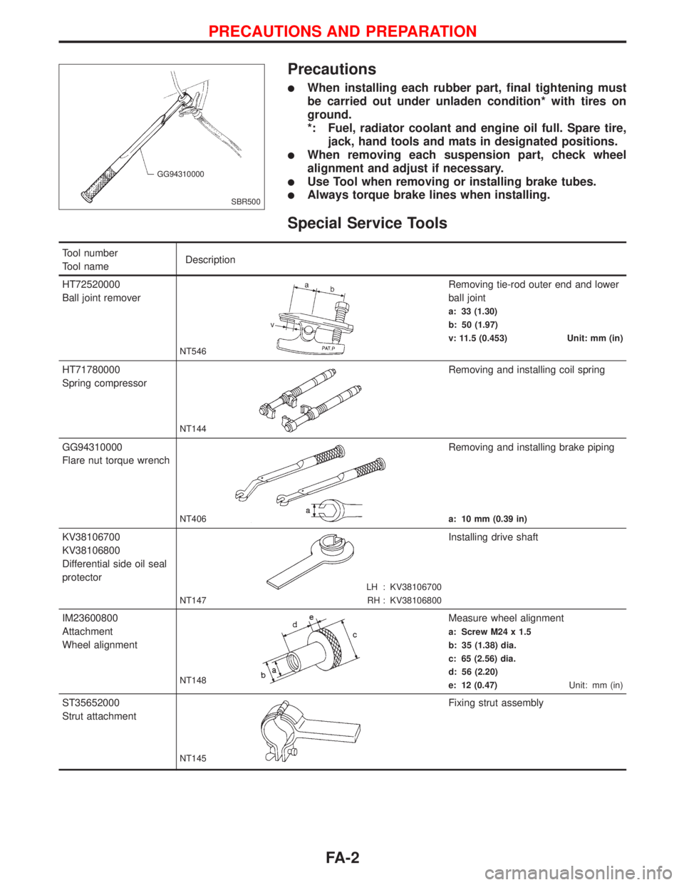
Precautions
lWhen installing each rubber part, final tightening must
be carried out under unladen condition* with tires on
ground.
*: Fuel, radiator coolant and engine oil full. Spare tire,
jack, hand tools and mats in designated positions.
lWhen removing each suspension part, check wheel
alignment and adjust if necessary.
lUse Tool when removing or installing brake tubes.
lAlways torque brake lines when installing.
Special Service Tools
Tool number
Tool nameDescription
HT72520000
Ball joint remover
NT546
Removing tie-rod outer end and lower
ball joint
a: 33 (1.30)
b: 50 (1.97)
v: 11.5 (0.453) Unit: mm (in)
HT71780000
Spring compressor
NT144
Removing and installing coil spring
GG94310000
Flare nut torque wrench
NT406
Removing and installing brake piping
a: 10 mm (0.39 in)
KV38106700
KV38106800
Differential side oil seal
protector
LH : KV38106700
RH : KV38106800 NT147
Installing drive shaft
IM23600800
Attachment
Wheel alignment
NT148
Measure wheel alignment
a: Screw M24 x 1.5
b: 35 (1.38) dia.
c: 65 (2.56) dia.
d: 56 (2.20)
e: 12 (0.47)Unit: mm (in)
ST35652000
Strut attachment
NT145
Fixing strut assembly
SBR500 GG94310000
PRECAUTIONS AND PREPARATION
FA-2
Page 1745 of 2267

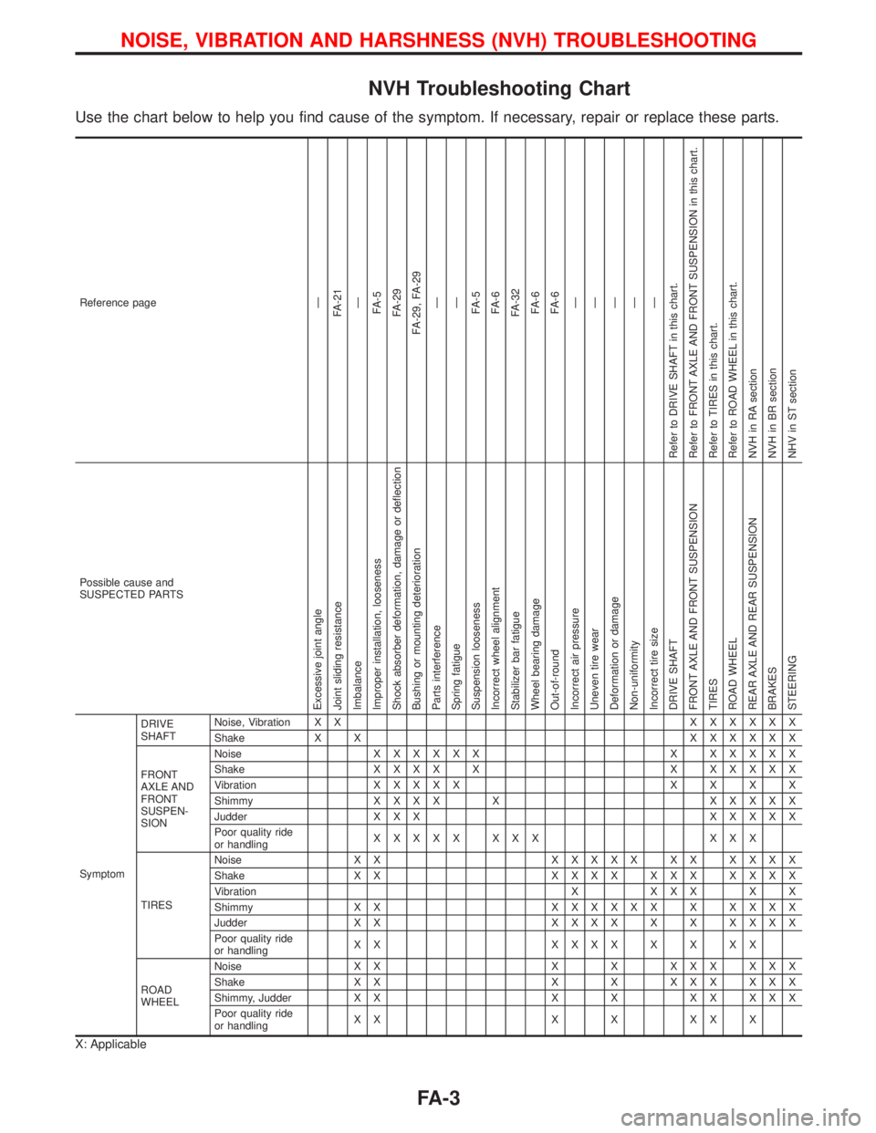
NVH Troubleshooting Chart
Use the chart below to help you find cause of the symptom. If necessary, repair or replace these parts.
Reference pageÐ
FA-21
Ð
FA-5
FA-29
FA-29, FA-29
Ð
Ð
FA-5
FA-6
FA-32
FA-6
FA-6
Ð
Ð
Ð
Ð
Ð
Refer to DRIVE SHAFT in this chart.
Refer to FRONT AXLE AND FRONT SUSPENSION in this chart.
Refer to TIRES in this chart.
Refer to ROAD WHEEL in this chart.
NVH in RA section
NVH in BR section
NHV in ST section
Possible cause and
SUSPECTED PARTS
Excessive joint angle
Joint sliding resistance
Imbalance
Improper installation, looseness
Shock absorber deformation, damage or deflection
Bushing or mounting deterioration
Parts interference
Spring fatigue
Suspension looseness
Incorrect wheel alignment
Stabilizer bar fatigue
Wheel bearing damage
Out-of-round
Incorrect air pressure
Uneven tire wear
Deformation or damage
Non-uniformity
Incorrect tire size
DRIVE SHAFT
FRONT AXLE AND FRONT SUSPENSION
TIRES
ROAD WHEEL
REAR AXLE AND REAR SUSPENSION
BRAKES
STEERING
SymptomDRIVE
SHAFTNoise, Vibration X XXXXXXX
Shake X XXXXXXX
FRONT
AXLE AND
FRONT
SUSPEN-
SIONNoiseXXXXXX X XXXXX
ShakeXXXX X X XXXXX
VibrationXXXXXXXXX
ShimmyXXXX X XXXXX
Judder X X XXXXXX
Poor quality ride
or handlingXXXXX XXX XXX
TIRESNoise X XXXXXX XX XXXX
Shake X XXXXX XXX XXXX
Vibration X X X X X X
Shimmy X XXXXXXX X XXXX
Judder X XXXXX X X XXXX
Poor quality ride
or handlingXX XXXXXXXX
ROAD
WHEELNoise X X X X X X X X X X
Shake X X X X X X X X X X
Shimmy, Judder X X X X X X X X X
Poor quality ride
or handlingXX X X XX X
X: Applicable
NOISE, VIBRATION AND HARSHNESS (NVH) TROUBLESHOOTING
FA-3