1999 NISSAN PRIMERA glove box
[x] Cancel search: glove boxPage 229 of 2267
CAUTION:
lDisconnect both battery cables in advance.
lDisconnect air bag system line in advance.
lNever tamper with or force air bag lid open, as this may adversely affect air bag performance.
lBe careful not to scratch pad and other parts.
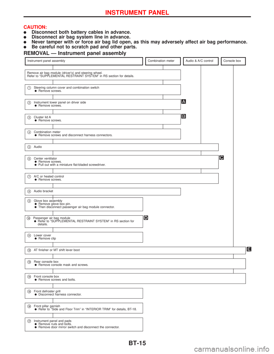
REMOVAL Ð Instrument panel assembly
Instrument panel assemblyCombination meterAudio & A/C controlConsole box
Remove air bag module (driver's) and steering wheel.
Refer to ªSUPPLEMENTAL RESTRAINT SYSTEMº in RS section for details.
p1Steering column cover and combination switchlRemove screws.
p2Instrument lower panel on driver sidelRemove screws.
p3Cluster lid AlRemove screws.
p4Combination meterlRemove screws and disconnect harness connectors.
p5Audio
p6Center ventilatorlRemove screws.lPull out with a miniature flat-bladed screwdriver.
p7A/C or heated controllRemove screws.
p8Audio bracket
p9Glove box assemblylRemove glove box pin.lThen disconnect passenger air bag module connector.
p10Passenger air bag modulelRefer to ªSUPPLEMENTAL RESTRAINT SYSTEMº in RS section for
details.
p11Lower coverlRemove clip
p12AT finisher or MT shift lever boot
p13Rear console boxlRemove console mask and screws.
p14Front console boxlRemove screws and bolts.
p15Front defroster grilllDisconnect harness connector.
p16Front pillar garnishlRefer to ªSide and Floor Trimº in ªINTERIOR TRIMº for details, BT-18.
p17Instrument panel and padslRemove nuts and bolts.lRemove door mirror switch and disconnect the connector.
INSTRUMENT PANEL
BT-15
Page 817 of 2267
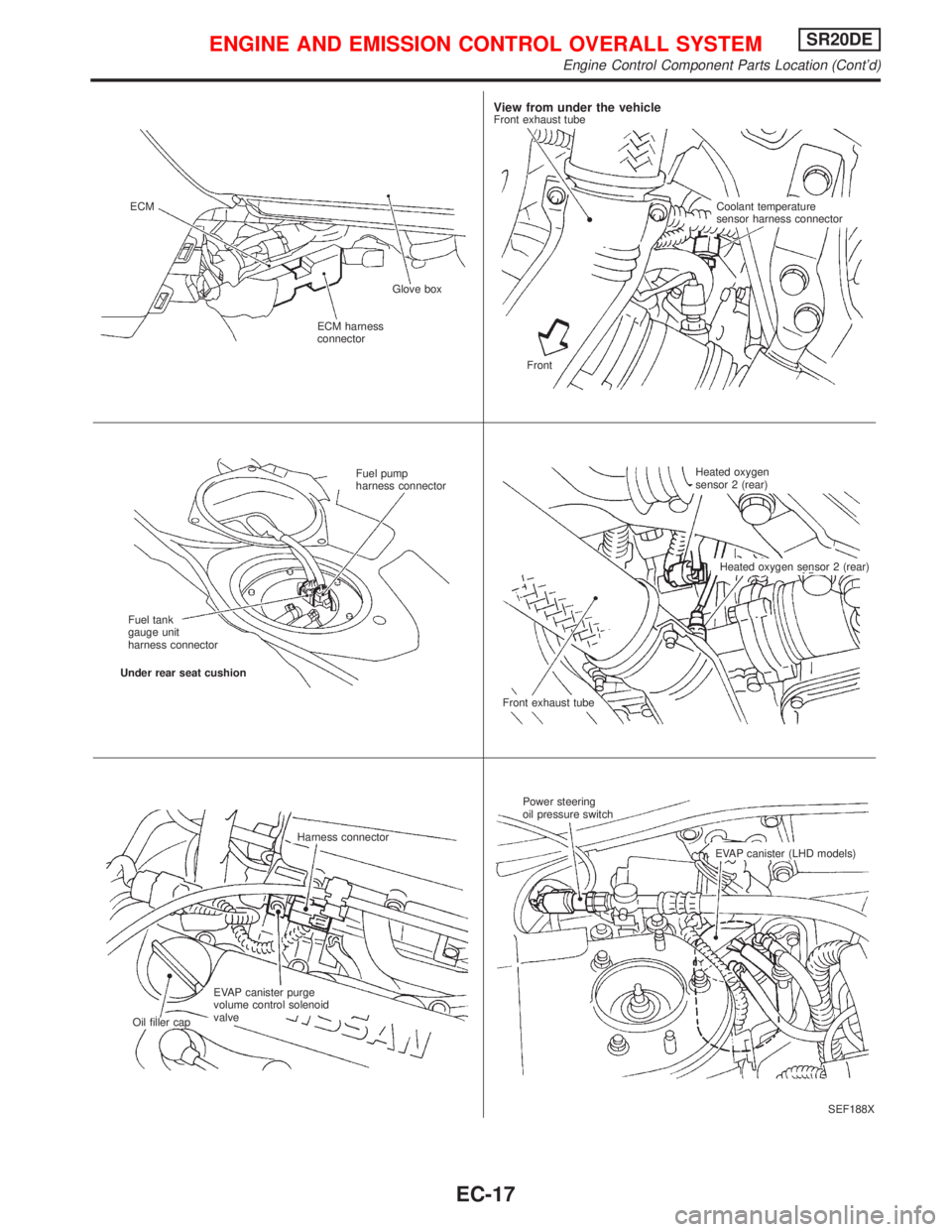
SEF188X ECM
ECM harness
connectorGlove box
View from under the vehicleFront exhaust tube
Coolant temperature
sensor harness connector
Front
Fuel pump
harness connector
Fuel tank
gauge unit
harness connector
Under rear seat cushion
Front exhaust tubeHeated oxygen
sensor 2 (rear)
Heated oxygen sensor 2 (rear)
Harness connector
EVAP canister purge
volume control solenoid
valve
Oil filler capPower steering
oil pressure switch
EVAP canister (LHD models)
ENGINE AND EMISSION CONTROL OVERALL SYSTEMSR20DE
Engine Control Component Parts Location (Cont'd)
EC-17
Page 1149 of 2267
YEL225C
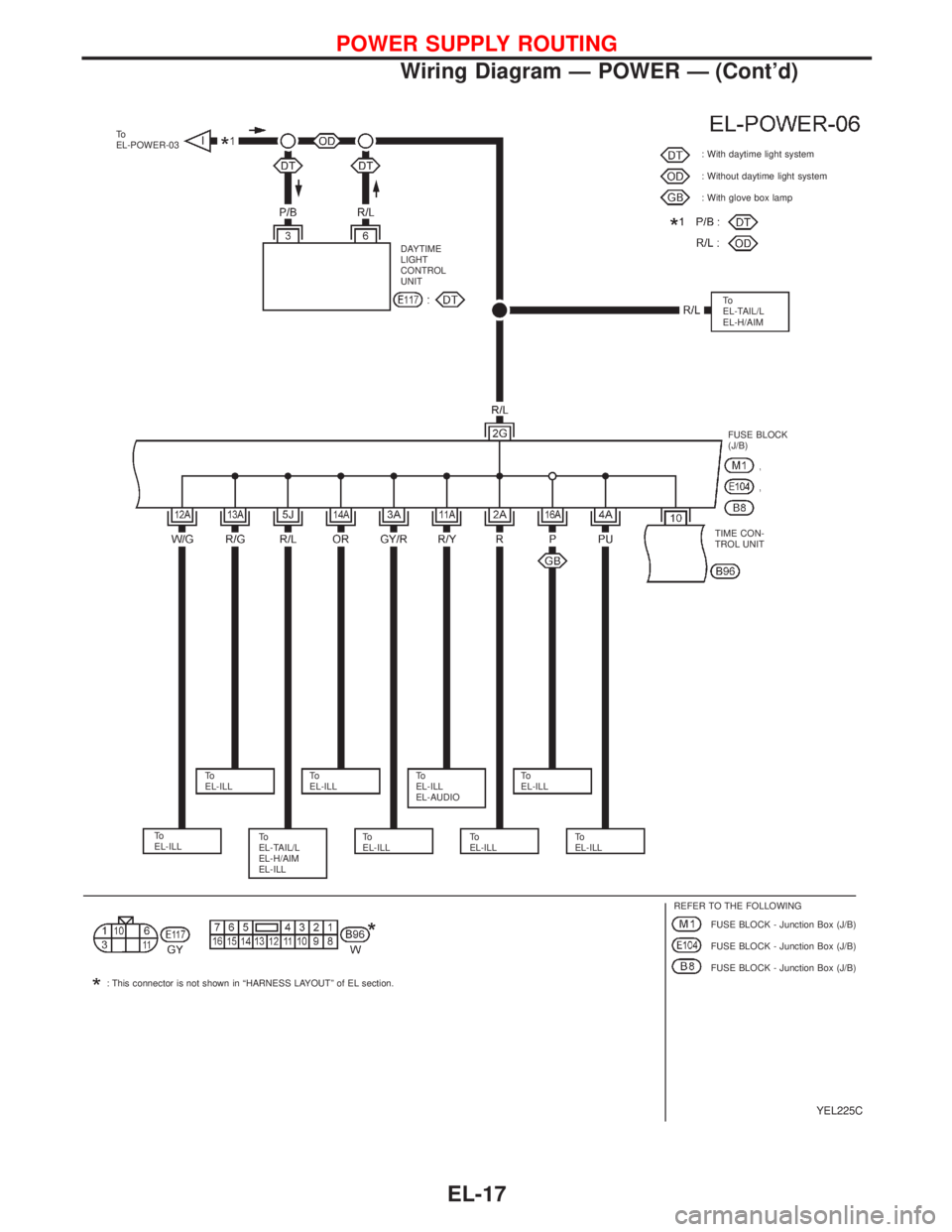
To
EL-POWER-03
DAYTIME
LIGHT
CONTROL
UNIT: With daytime light system
: Without daytime light system
: With glove box lamp
FUSE BLOCK
(J/B)
To
EL-ILLTo
EL-ILLTo
EL-ILL
EL-AUDIOTo
EL-ILL
To
EL-TAIL/L
EL-H/AIM
EL-ILLTo
EL-ILLTo
EL-ILLTo
EL-ILL
REFER TO THE FOLLOWING
FUSE BLOCK - Junction Box (J/B)
FUSE BLOCK - Junction Box (J/B)
FUSE BLOCK - Junction Box (J/B) To
EL-ILL
: This connector is not shown in“HARNESS LAYOUT”of EL section.TIME CON-
TROL UNITTo
EL-TAIL/L
EL-H/AIM
POWER SUPPLY ROUTING
Wiring Diagram—POWER—(Cont’d)
EL-17
Page 1155 of 2267
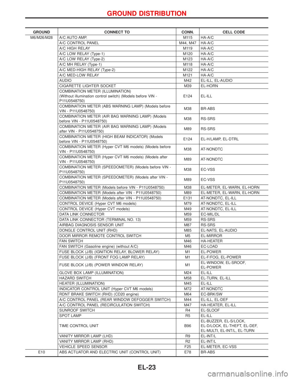
GROUND CONNECT TO CONN. CELL CODE
M6/M26/M28 A/C AUTO AMP. M115 HA-A/C
A/C CONTROL PANEL M44, M47 HA-A/C
A/C HIGH RELAY M119 HA-A/C
A/C LOW RELAY (Type-1) M120 HA-A/C
A/C LOW RELAY (Type-2) M123 HA-A/C
A/C MH RELAY (Type-1) M118 HA-A/C
A/C MED-HIGH RELAY (Type-2) M122 HA-A/C
A/C MED-LOW RELAY M121 HA-A/C
AUDIO M42 EL-ILL, EL-AUDIO
CIGARETTE LIGHTER SOCKET M39 EL-HORN
COMBINATION METER (ILLUMINATION)
(Without illumination control switch) (Models before VIN -
P11U0548750)E124 EL-ILL
COMBINATION METER (ABS WARNING LAMP) (Models before
VIN - P11U0548750)M38 BR-ABS
COMBINATION METER (AIR BAG WARNING LAMP) (Models
before VIN - P11U0548750)M38 RS-SRS
COMBINATION METER (AIR BAG WARNING LAMP) (Models
after VIN - P11U0548750)M89 RS-SRS
COMBINATION METER (HIGH BEAM INDICATOR) (Models
before VIN - P11U0548750)E124 EL-H/LAMP, EL-DTRL
COMBINATION METER (Hyper CVT M6 models) (Models before
VIN - P11U0548750)M38 AT-NONDTC
COMBINATION METER (Hyper CVT M6 models) (Models after
VIN - P11U0548750)M89 AT-NONDTC
COMBINATION METER (SPEEDOMETER) (Models before VIN -
P11U0548750)M38 EC-VSS
COMBINATION METER (SPEEDOMETER) (Models after VIN -
P11U0548750)M89 EC-VSS
COMBINATION METER (Models before VIN - P11U0548750) M38 EL-METER, EL-WARN, EL-HORN
COMBINATION METER (Models after VIN - P11U0548750) M89 EL-METER, EL-WARN, EL-HORN
COMBINATION METER (Models after VIN - P11U0548750) E131 AT-NONDTC, EL-ILL
CONTROL DEVICE (Hyper CVT M6 models) M79 AT-NONDTC, EL-ILL
CONTROL DEVICE (Hyper CVT models) M49 AT-NONDTC, EL-ILL
DATA LINK CONNECTOR M59 EC-MIL/DL
DATA LINK CONNECTOR (TERMINAL NO. 13) M59 RS-SRS
AIRBAG DIAGNOSIS SENSOR UNIT M87 RS-SRS
DONGLE CONTROL UNIT (RHD) M85 EL-NATS, EL-AUDIO
DOOR MIRROR REMOTE CONTROL SWITCH M5 EL-MIRROR
FAN SWITCH M46 HA-HEATER
FAN SWITCH (Gasoline engine) (without A/C) M46 EC-LOAD
FUSE BLOCK (J/B) (IGNITION RELAY, BLOWER RELAY) M1 EL-POWER
FUSE BLOCK (J/B) (FRONT FOG LAMP RELAY) M1 EL-F/FOG, EL-POWER
FUSE BLOCK (J/B) (POWER WINDOW RELAY) M1EL-WINDOW, EL-SROOF,
EL-POWER
GLOVE BOX LAMP (ILLUMINATION) M24 EL-ILL
HAZARD SWITCH M58 EL-TURN, EL-ILL
HEATER (ILLUMINATION) M45 EL-ILL
INDICATOR CONTROL UNIT (Hyper CVT M6 models) M72 AT-NONDTC
RDNT BRAKE SWITCH (RHD) (CD20 engine) M64 EC-BRK/SW
A/C CONTROL PANEL (REAR WINDOW DEFOGGER SWITCH) M44 EL-ILL, EL-DEF
A/C CONTROL PANEL (RECIRCULATION SWITCH) M47 HA-HEATER, EL-ILL
SUNROOF SWITCH R4 EL-SLOOF
SPOT LAMP R5 EL-ILL
TIME CONTROL UNIT B96EL-BUZZER, EL-S/LOCK,
EL-D/LOCK, EL-THEFT, EL-DEF,
EL-MULTI, EL-INT/L, EL-TURN
VANITY MIRROR LAMP (LHD) R9 EL-INT/L
VANITY MIRROR LAMP (RHD) R2 EL-INT/L
VEHICLE SPEED SENSOR F25 EL-METER, EC-VSS
E10 ABS ACTUATOR AND ELECTRIC UNIT (CONTROL UNIT) E78 BR-ABS
GROUND DISTRIBUTION
EL-23
Page 1966 of 2267
BREAK-IN OPERATION
When replacing compressor clutch assembly, always carry out
the break-in operation. This is done by engaging and disengag-
ing the clutch about thirty times. Break-in operation raises the
level of transmitted torque.
Ventilation Air Filter
FUNCTION
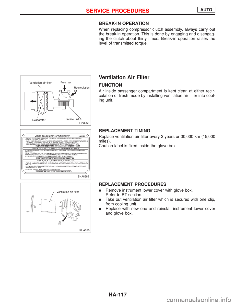
Air inside passenger compartment is kept clean at either recir-
culation or fresh mode by installing ventilation air filter into cool-
ing unit.
REPLACEMENT TIMING
Replace ventilation air filter every 2 years or 30,000 km (15,000
miles).
Caution label is fixed inside the glove box.
REPLACEMENT PROCEDURES
lRemove instrument lower cover with glove box.
Refer to BT section.
lTake out ventilation air filter which is secured with one clip,
from cooling unit.
lReplace with new one and reinstall instrument lower cover
and glove box.
RHA336F Ventilation air filterFresh air
Recirculation
air
EvaporatorIntake unit
SHA868E
KHA058 Ventilation air filter
SERVICE PROCEDURESAUTO
HA-117
Page 2200 of 2267
If air bag warning lamp blinks or stays ON (at the user mode),
it shows the spiral cable may be snapped due to its improper
position. Perform self-diagnosis again (use CONSULT-II or
warning lamp). If a malfunction is detected, replace the spi-
ral cable with a new one.
13. Perform self-diagnosis again to check that no malfunction is
detected.
Removal Ð Front Passenger's Air Bag
Module
CAUTION:
lBefore servicing SRS, turn the ignition switch ªOFFº,
disconnect both battery cables and wait at least 3 min-
utes.
lAlways work from the side of or under air bag module.
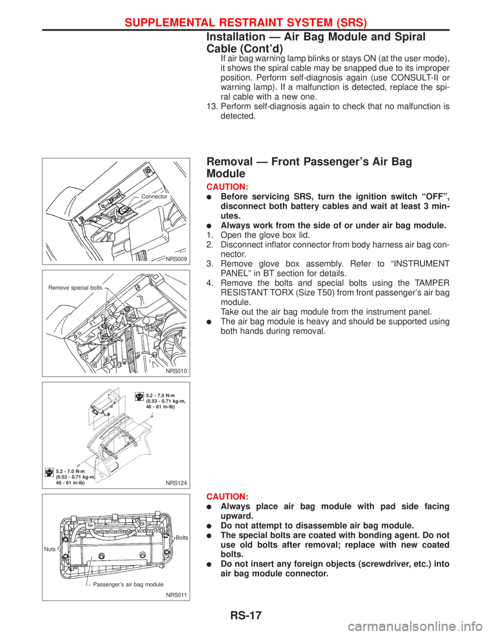
1. Open the glove box lid.
2. Disconnect inflator connector from body harness air bag con-
nector.
3. Remove glove box assembly. Refer to ªINSTRUMENT
PANELº in BT section for details.
4. Remove the bolts and special bolts using the TAMPER
RESISTANT TORX (Size T50) from front passenger's air bag
module.
Take out the air bag module from the instrument panel.
lThe air bag module is heavy and should be supported using
both hands during removal.
CAUTION:
lAlways place air bag module with pad side facing
upward.
lDo not attempt to disassemble air bag module.
lThe special bolts are coated with bonding agent. Do not
use old bolts after removal; replace with new coated
bolts.
lDo not insert any foreign objects (screwdriver, etc.) into
air bag module connector.
.NRS009
.Connector
.NRS010
.Remove special bolts
NRS124
5.2 - 7.0 N´m
(0.53 - 0.71 kg-m,
46 - 61 in-lb)
5.2 - 7.0 N´m
(0.53 - 0.71 kg-m,
46 - 61 in-lb)
NRS011 Nuts
Passenger's air bag moduleBolts
SUPPLEMENTAL RESTRAINT SYSTEM (SRS)
Installation Ð Air Bag Module and Spiral
Cable (Cont'd)
RS-17
Page 2201 of 2267
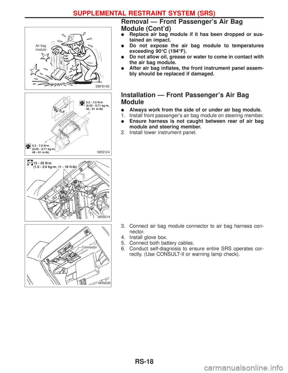
lReplace air bag module if it has been dropped or sus-
tained an impact.
lDo not expose the air bag module to temperatures
exceeding 90ÉC (194ÉF).
lDo not allow oil, grease or water to come in contact with
the air bag module.
lAfter air bag inflates, the front instrument panel assem-
bly should be replaced if damaged.
Installation Ð Front Passenger's Air Bag
Module
lAlways work from the side of or under air bag module.
1. Install front passenger's air bag module on steering member.
lEnsure harness is not caught between rear of air bag
module and steering member.
2. Install lower instrument panel.
3. Connect air bag module connector to air bag harness con-
nector.
4. Install glove box.
5. Connect both battery cables.
6. Conduct self-diagnosis to ensure entire SRS operates cor-
rectly. (Use CONSULT-II or warning lamp check).
SBF814E Air bag
module
NRS124
5.2 - 7.0 N´m
(0.53 - 0.71 kg-m,
46 - 61 in-lb)
5.2 - 7.0 N´m
(0.53 - 0.71 kg-m,
46 - 61 in-lb)
.NRS014
.15-25N´m
(1.5 - 2.5 kg-m, 11 - 18 ft-lb)
.NRS009
.Connector
SUPPLEMENTAL RESTRAINT SYSTEM (SRS)
Removal Ð Front Passenger's Air Bag
Module (Cont'd)
RS-18