1999 NISSAN PRIMERA heater
[x] Cancel search: heaterPage 346 of 2267
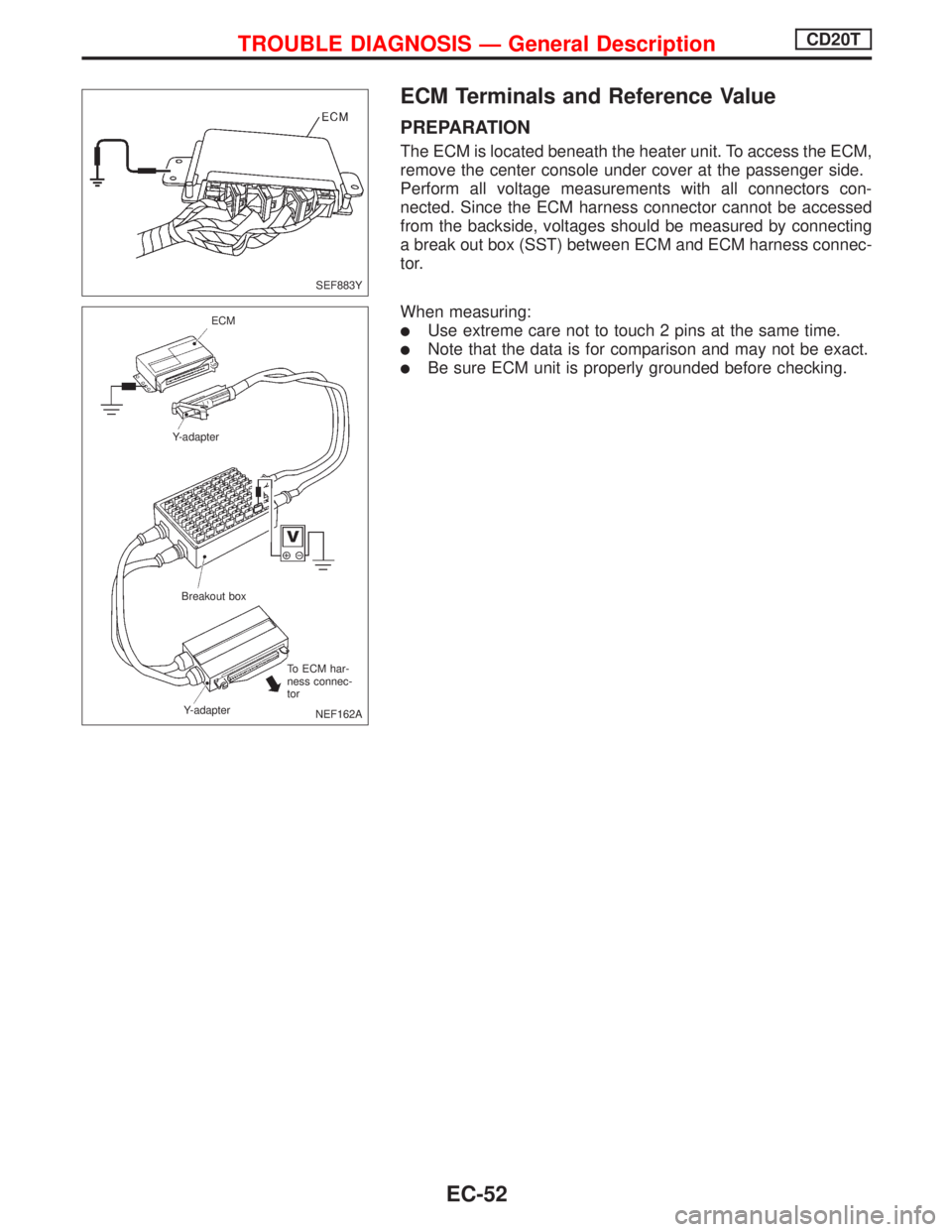
ECM Terminals and Reference Value
PREPARATION
The ECM is located beneath the heater unit. To access the ECM,
remove the center console under cover at the passenger side.
Perform all voltage measurements with all connectors con-
nected. Since the ECM harness connector cannot be accessed
from the backside, voltages should be measured by connecting
a break out box (SST) between ECM and ECM harness connec-
tor.
When measuring:
lUse extreme care not to touch 2 pins at the same time.
lNote that the data is for comparison and may not be exact.
lBe sure ECM unit is properly grounded before checking.
SEF883Y
NEF162A ECM
Y-adapter
Breakout box
Y-adapterTo ECM har-
ness connec-
tor
TROUBLE DIAGNOSIS Ð General DescriptionCD20T
EC-52
Page 412 of 2267
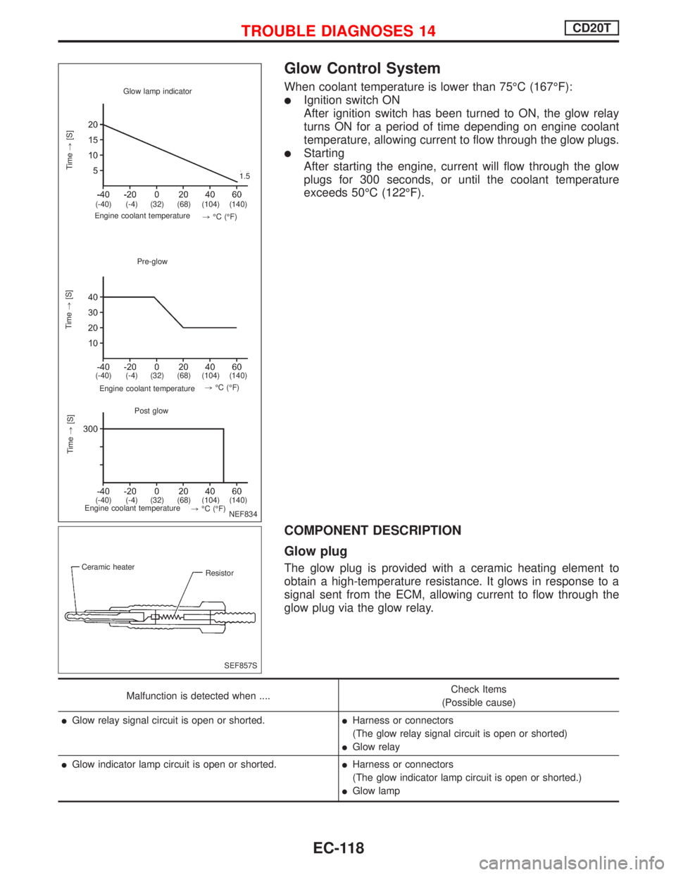
Glow Control System
When coolant temperature is lower than 75ÉC (167ÉF):
lIgnition switch ON
After ignition switch has been turned to ON, the glow relay
turns ON for a period of time depending on engine coolant
temperature, allowing current to flow through the glow plugs.
lStarting
After starting the engine, current will flow through the glow
plugs for 300 seconds, or until the coolant temperature
exceeds 50ÉC (122ÉF).
COMPONENT DESCRIPTION
Glow plug
The glow plug is provided with a ceramic heating element to
obtain a high-temperature resistance. It glows in response to a
signal sent from the ECM, allowing current to flow through the
glow plug via the glow relay.
Malfunction is detected when ....Check Items
(Possible cause)
lGlow relay signal circuit is open or shorted.lHarness or connectors
(The glow relay signal circuit is open or shorted)
lGlow relay
lGlow indicator lamp circuit is open or shorted.lHarness or connectors
(The glow indicator lamp circuit is open or shorted.)
lGlow lamp
Glow lamp indicator
Time,[S]
.
Engine coolant temperature
Pre-glow
Time,[S]
Engine coolant temperature.
Post glow
.Time,[S]
Engine coolant temperature
.1.5
.(-40) (-4) (32) (68) (104) (140)
.(-40) (-4) (32) (68) (104) (140)
.(-40) (-4) (32) (68) (104) (140),ÉC (ÉF).,ÉC (ÉF)
.,ÉC (ÉF)
NEF834
.
.
SEF857S Ceramic heater
Resistor
TROUBLE DIAGNOSES 14CD20T
EC-118
Page 444 of 2267
DTC P0100 MASS AIR FLOW SENSOR (MAFS)...... 110
Component Description ........................................... 110
CONSULT-II Reference Value in Data Monitor
Mode ........................................................................ 110
ECM Terminals and Reference Value ..................... 110
On Board Diagnosis Logic....................................... 110
DTC Confirmation Procedure .................................. 111
Wiring Diagram ........................................................ 112
Diagnostic Procedure .............................................. 113
Component Inspection ............................................. 115
DTC P0110 INTAKE AIR TEMPERATURE
SENSOR...................................................................... 116
Component Description ........................................... 116
On Board Diagnosis Logic....................................... 116
DTC Confirmation Procedure .................................. 116
Wiring Diagram ........................................................ 117
Diagnostic Procedure .............................................. 118
Component Inspection ............................................. 119
DTC P0115 ENGINE COOLANT TEMPERATURE
SENSOR (ECTS) (CIRCUIT).......................................120
Component Description ...........................................120
CONSULT-II Reference Value in Data Monitor
Mode ........................................................................120
On Board Diagnosis Logic.......................................120
DTC Confirmation Procedure ..................................121
Wiring Diagram ........................................................122
Diagnostic Procedure ..............................................123
Component Inspection .............................................124
DTC P0120 THROTTLE POSITION SENSOR...........125
Component Description ...........................................125
CONSULT-II Reference Value in Data Monitor
Mode ........................................................................125
ECM Terminals and Reference Value .....................126
On Board Diagnosis Logic.......................................126
DTC Confirmation Procedure ..................................126
Wiring Diagram ........................................................128
Diagnostic Procedure ..............................................129
Component Inspection .............................................131
DTC P0130 HEATED OXYGEN SENSOR 1
(FRONT) (CIRCUIT).....................................................132
Component Description ...........................................132
CONSULT-II Reference Value in Data Monitor
Mode ........................................................................132
ECM Terminals and Reference Value .....................132
On Board Diagnosis Logic.......................................133
DTC Confirmation Procedure ..................................133
Overall Function Check ...........................................134
Wiring Diagram ........................................................135
Diagnostic Procedure ..............................................136
Component Inspection .............................................137DTC P0131 HEATED OXYGEN SENSOR 1
(FRONT) (LEAN SHIFT MONITORING).....................139
Component Description ...........................................139
CONSULT-II Reference Value in Data Monitor
Mode ........................................................................139
ECM Terminals and Reference Value .....................139
On Board Diagnosis Logic.......................................140
DTC Confirmation Procedure ..................................140
Overall Function Check ...........................................141
Diagnostic Procedure ..............................................141
Component Inspection .............................................143
DTC P0132 HEATED OXYGEN SENSOR 1
(FRONT) (RICH SHIFT MONITORING)......................145
Component Description ...........................................145
CONSULT-II Reference Value in Data Monitor
Mode ........................................................................145
ECM Terminals and Reference Value .....................145
On Board Diagnosis Logic.......................................146
DTC Confirmation Procedure ..................................146
Overall Function Check ...........................................147
Diagnostic Procedure ..............................................147
Component Inspection .............................................149
DTC P0133 HEATED OXYGEN SENSOR 1
(FRONT) (RESPONSE MONITORING).......................151
Component Description ...........................................151
CONSULT-II Reference Value in Data Monitor
Mode ........................................................................151
ECM Terminals and Reference Value .....................151
On Board Diagnosis Logic.......................................152
DTC Confirmation Procedure ..................................152
Overall Function Check ...........................................153
Wiring Diagram ........................................................154
Diagnostic Procedure ..............................................155
Component Inspection .............................................158
DTC P0134 HEATED OXYGEN SENSOR 1
(FRONT) (HIGH VOLTAGE)........................................160
Component Description ...........................................160
CONSULT-II Reference Value in Data Monitor
Mode ........................................................................160
ECM Terminals and Reference Value .....................160
On Board Diagnosis Logic.......................................161
DTC Confirmation Procedure ..................................161
Wiring Diagram ........................................................162
Diagnostic Procedure ..............................................163
Component Inspection .............................................164
DTC P0135 HEATED OXYGEN SENSOR 1
(FRONT) HEATER.......................................................166
Description ...............................................................166
CONSULT-II Reference Value in Data Monitor
Mode ........................................................................166
ECM Terminals and Reference Value .....................166
On Board Diagnosis Logic.......................................166
CONTENTS(Cont'd)
EC-2
Page 445 of 2267
DTC Confirmation Procedure ..................................167
Wiring Diagram ........................................................168
Diagnostic Procedure ..............................................169
Component Inspection .............................................170
DTC P0137 HEATED OXYGEN SENSOR 2
(REAR) (MIN. VOLTAGE MONITORING)...................171
Component Description ...........................................171
CONSULT-II Reference Value in Data Monitor
Mode ........................................................................171
ECM Terminals and Reference Value .....................171
On Board Diagnosis Logic.......................................171
DTC Confirmation Procedure ..................................172
Overall Function Check ...........................................173
Wiring Diagram ........................................................174
Diagnostic Procedure ..............................................175
Component Inspection .............................................178
DTC P0138 HEATED OXYGEN SENSOR 2
(REAR) (MAX. VOLTAGE MONITORING).................180
Component Description ...........................................180
CONSULT-II Reference Value in Data Monitor
Mode ........................................................................180
ECM Terminals and Reference Value .....................180
On Board Diagnosis Logic.......................................180
DTC Confirmation Procedure ..................................181
Overall Function Check ...........................................182
Wiring Diagram ........................................................183
Diagnostic Procedure ..............................................184
Component Inspection .............................................186
DTC P0139 HEATED OXYGEN SENSOR 2
(REAR) (RESPONSE MONITORING).........................188
Component Description ...........................................188
CONSULT-II Reference Value in Data Monitor
Mode ........................................................................188
ECM Terminals and Reference Value .....................188
On Board Diagnosis Logic.......................................188
DTC Confirmation Procedure ..................................189
Overall Function Check ...........................................190
Wiring Diagram ........................................................191
Diagnostic Procedure ..............................................192
Component Inspection .............................................195
DTC P0140 HEATED OXYGEN SENSOR 2
(REAR) (HIGH VOLTAGE)..........................................197
Component Description ...........................................197
CONSULT-II Reference Value in Data Monitor
Mode ........................................................................197
ECM Terminals and Reference Value .....................197
On Board Diagnosis Logic.......................................197
DTC Confirmation Procedure ..................................198
Overall Function Check ...........................................198
Wiring Diagram ........................................................199
Diagnostic Procedure ..............................................200
Component Inspection .............................................201DTC P0141 HEATED OXYGEN SENSOR 2
HEATER (REAR).........................................................203
Description ...............................................................203
CONSULT-II Reference Value in Data Monitor
Mode ........................................................................203
ECM Terminals and Reference Value .....................203
On Board Diagnosis Logic.......................................204
DTC Confirmation Procedure ..................................204
Wiring Diagram ........................................................205
Diagnostic Procedure ..............................................206
Component Inspection .............................................207
DTC P0171 FUEL INJECTION SYSTEM
FUNCTION (LEAN SIDE)............................................208
On Board Diagnosis Logic.......................................208
DTC Confirmation Procedure ..................................208
Wiring Diagram ........................................................210
Diagnostic Procedure .............................................. 211
DTC P0172 FUEL INJECTION SYSTEM
FUNCTION (RICH SIDE).............................................215
On Board Diagnosis Logic.......................................215
DTC Confirmation Procedure ..................................215
Wiring Diagram ........................................................217
Diagnostic Procedure ..............................................218
DTC P0300 - P0304 NO.4-1CYLINDER
MISFIRE, MULTIPLE CYLINDER MISFIRE................222
On Board Diagnosis Logic.......................................222
DTC Confirmation Procedure ..................................222
Diagnostic Procedure ..............................................223
DTC P0325 KNOCK SENSOR (KS)...........................228
Component Description ...........................................228
ECM Terminals and Reference Value .....................228
On Board Diagnosis Logic.......................................228
DTC Confirmation Procedure ..................................228
Wiring Diagram ........................................................229
Diagnostic Procedure ..............................................230
Component Inspection .............................................231
DTC P0335 CRANKSHAFT POSITION SENSOR
(POS)............................................................................232
Component Description ...........................................232
ECM Terminals and Reference Value .....................232
On Board Diagnosis Logic.......................................233
DTC Confirmation Procedure ..................................233
Wiring Diagram ........................................................234
Diagnostic Procedure ..............................................235
Component Inspection .............................................237
DTC P0340 CAMSHAFT POSITION SENSOR
(CMPS) (PHASE).........................................................238
Component Description ...........................................238
ECM Terminals and Reference Value .....................238
On Board Diagnosis Logic.......................................238
DTC Confirmation Procedure ..................................239
Wiring Diagram ........................................................240
CONTENTS(Cont'd)
EC-3
Page 447 of 2267
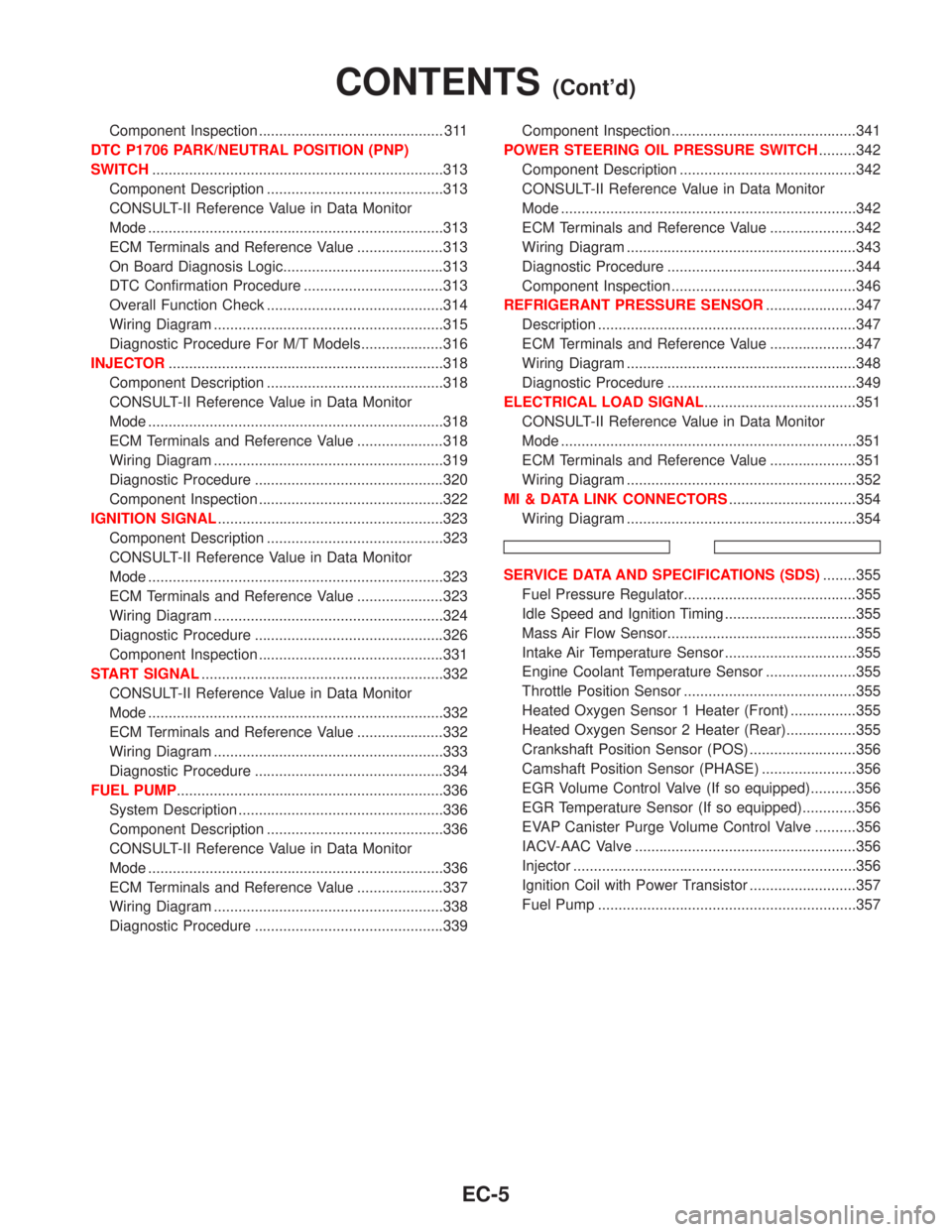
Component Inspection ............................................. 311
DTC P1706 PARK/NEUTRAL POSITION (PNP)
SWITCH.......................................................................313
Component Description ...........................................313
CONSULT-II Reference Value in Data Monitor
Mode ........................................................................313
ECM Terminals and Reference Value .....................313
On Board Diagnosis Logic.......................................313
DTC Confirmation Procedure ..................................313
Overall Function Check ...........................................314
Wiring Diagram ........................................................315
Diagnostic Procedure For M/T Models....................316
INJECTOR...................................................................318
Component Description ...........................................318
CONSULT-II Reference Value in Data Monitor
Mode ........................................................................318
ECM Terminals and Reference Value .....................318
Wiring Diagram ........................................................319
Diagnostic Procedure ..............................................320
Component Inspection .............................................322
IGNITION SIGNAL.......................................................323
Component Description ...........................................323
CONSULT-II Reference Value in Data Monitor
Mode ........................................................................323
ECM Terminals and Reference Value .....................323
Wiring Diagram ........................................................324
Diagnostic Procedure ..............................................326
Component Inspection .............................................331
START SIGNAL...........................................................332
CONSULT-II Reference Value in Data Monitor
Mode ........................................................................332
ECM Terminals and Reference Value .....................332
Wiring Diagram ........................................................333
Diagnostic Procedure ..............................................334
FUEL PUMP.................................................................336
System Description ..................................................336
Component Description ...........................................336
CONSULT-II Reference Value in Data Monitor
Mode ........................................................................336
ECM Terminals and Reference Value .....................337
Wiring Diagram ........................................................338
Diagnostic Procedure ..............................................339Component Inspection .............................................341
POWER STEERING OIL PRESSURE SWITCH.........342
Component Description ...........................................342
CONSULT-II Reference Value in Data Monitor
Mode ........................................................................342
ECM Terminals and Reference Value .....................342
Wiring Diagram ........................................................343
Diagnostic Procedure ..............................................344
Component Inspection .............................................346
REFRIGERANT PRESSURE SENSOR......................347
Description ...............................................................347
ECM Terminals and Reference Value .....................347
Wiring Diagram ........................................................348
Diagnostic Procedure ..............................................349
ELECTRICAL LOAD SIGNAL.....................................351
CONSULT-II Reference Value in Data Monitor
Mode ........................................................................351
ECM Terminals and Reference Value .....................351
Wiring Diagram ........................................................352
MI & DATA LINK CONNECTORS...............................354
Wiring Diagram ........................................................354
SERVICE DATA AND SPECIFICATIONS (SDS)........355
Fuel Pressure Regulator..........................................355
Idle Speed and Ignition Timing ................................355
Mass Air Flow Sensor..............................................355
Intake Air Temperature Sensor ................................355
Engine Coolant Temperature Sensor ......................355
Throttle Position Sensor ..........................................355
Heated Oxygen Sensor 1 Heater (Front) ................355
Heated Oxygen Sensor 2 Heater (Rear).................355
Crankshaft Position Sensor (POS) ..........................356
Camshaft Position Sensor (PHASE) .......................356
EGR Volume Control Valve (If so equipped)...........356
EGR Temperature Sensor (If so equipped).............356
EVAP Canister Purge Volume Control Valve ..........356
IACV-AAC Valve ......................................................356
Injector .....................................................................356
Ignition Coil with Power Transistor ..........................357
Fuel Pump ...............................................................357
CONTENTS(Cont'd)
EC-5
Page 462 of 2267
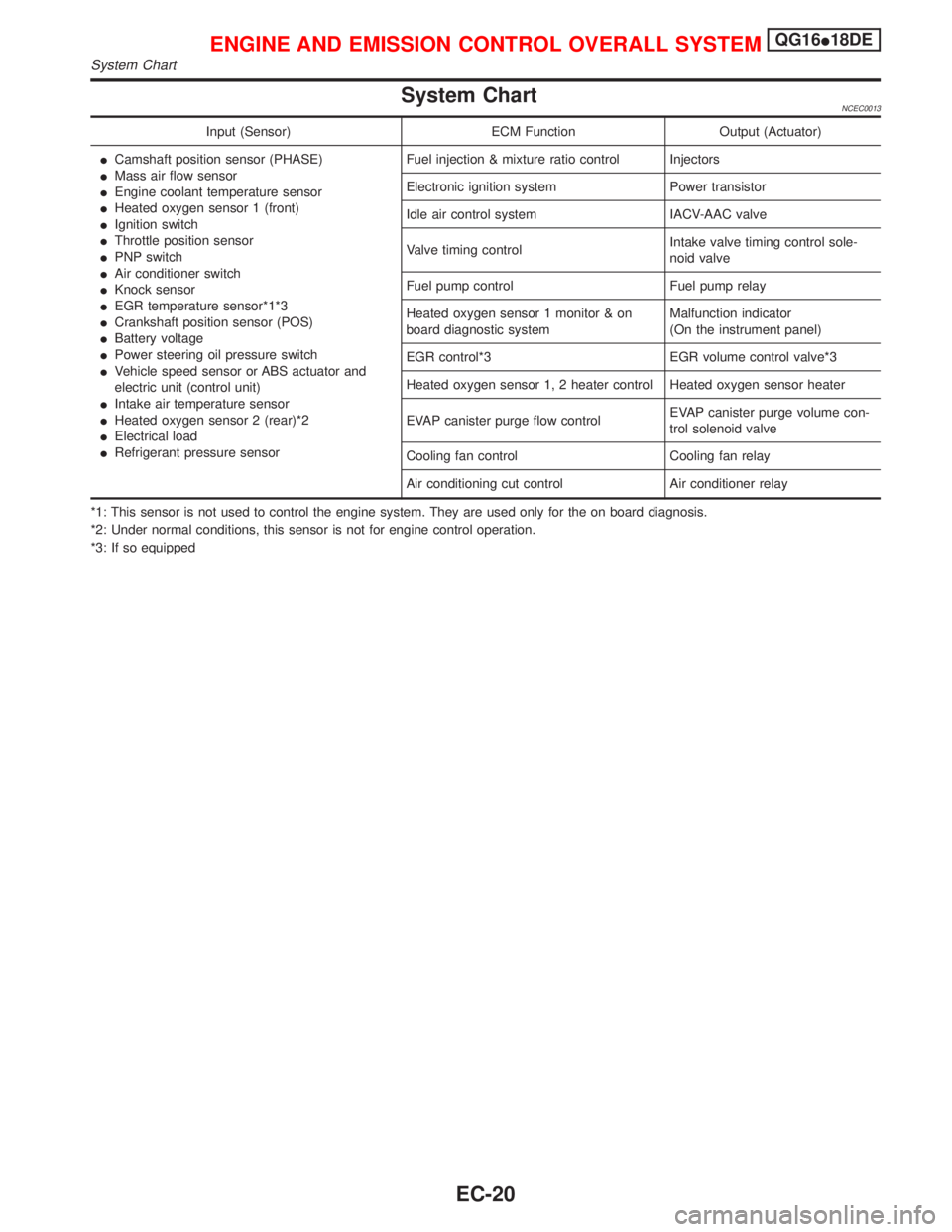
System ChartNCEC0013
Input (Sensor) ECM Function Output (Actuator)
ICamshaft position sensor (PHASE)
IMass air flow sensor
IEngine coolant temperature sensor
IHeated oxygen sensor 1 (front)
IIgnition switch
IThrottle position sensor
IPNP switch
IAir conditioner switch
IKnock sensor
IEGR temperature sensor*1*3
ICrankshaft position sensor (POS)
IBattery voltage
IPower steering oil pressure switch
IVehicle speed sensor or ABS actuator and
electric unit (control unit)
IIntake air temperature sensor
IHeated oxygen sensor 2 (rear)*2
IElectrical load
IRefrigerant pressure sensorFuel injection & mixture ratio control Injectors
Electronic ignition system Power transistor
Idle air control system IACV-AAC valve
Valve timing controlIntake valve timing control sole-
noid valve
Fuel pump control Fuel pump relay
Heated oxygen sensor 1 monitor & on
board diagnostic systemMalfunction indicator
(On the instrument panel)
EGR control*3 EGR volume control valve*3
Heated oxygen sensor 1, 2 heater control Heated oxygen sensor heater
EVAP canister purge flow controlEVAP canister purge volume con-
trol solenoid valve
Cooling fan control Cooling fan relay
Air conditioning cut control Air conditioner relay
*1: This sensor is not used to control the engine system. They are used only for the on board diagnosis.
*2: Under normal conditions, this sensor is not for engine control operation.
*3: If so equipped
ENGINE AND EMISSION CONTROL OVERALL SYSTEMQG16I18DE
System Chart
EC-20
Page 480 of 2267
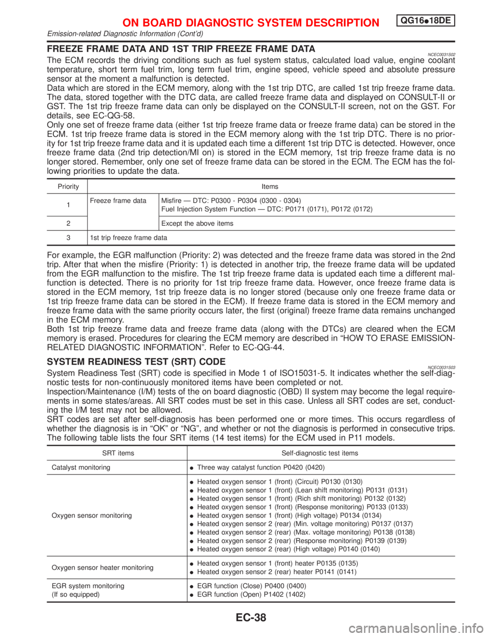
FREEZE FRAME DATA AND 1ST TRIP FREEZE FRAME DATANCEC0031S02The ECM records the driving conditions such as fuel system status, calculated load value, engine coolant
temperature, short term fuel trim, long term fuel trim, engine speed, vehicle speed and absolute pressure
sensor at the moment a malfunction is detected.
Data which are stored in the ECM memory, along with the 1st trip DTC, are called 1st trip freeze frame data.
The data, stored together with the DTC data, are called freeze frame data and displayed on CONSULT-II or
GST. The 1st trip freeze frame data can only be displayed on the CONSULT-II screen, not on the GST. For
details, see EC-QG-58.
Only one set of freeze frame data (either 1st trip freeze frame data or freeze frame data) can be stored in the
ECM. 1st trip freeze frame data is stored in the ECM memory along with the 1st trip DTC. There is no prior-
ity for 1st trip freeze frame data and it is updated each time a different 1st trip DTC is detected. However, once
freeze frame data (2nd trip detection/MI on) is stored in the ECM memory, 1st trip freeze frame data is no
longer stored. Remember, only one set of freeze frame data can be stored in the ECM. The ECM has the fol-
lowing priorities to update the data.
Priority Items
1Freeze frame data Misfire Ð DTC: P0300 - P0304 (0300 - 0304)
Fuel Injection System Function Ð DTC: P0171 (0171), P0172 (0172)
2 Except the above items
3 1st trip freeze frame data
For example, the EGR malfunction (Priority: 2) was detected and the freeze frame data was stored in the 2nd
trip. After that when the misfire (Priority: 1) is detected in another trip, the freeze frame data will be updated
from the EGR malfunction to the misfire. The 1st trip freeze frame data is updated each time a different mal-
function is detected. There is no priority for 1st trip freeze frame data. However, once freeze frame data is
stored in the ECM memory, 1st trip freeze data is no longer stored (because only one freeze frame data or
1st trip freeze frame data can be stored in the ECM). If freeze frame data is stored in the ECM memory and
freeze frame data with the same priority occurs later, the first (original) freeze frame data remains unchanged
in the ECM memory.
Both 1st trip freeze frame data and freeze frame data (along with the DTCs) are cleared when the ECM
memory is erased. Procedures for clearing the ECM memory are described in ªHOW TO ERASE EMISSION-
RELATED DIAGNOSTIC INFORMATIONº. Refer to EC-QG-44.
SYSTEM READINESS TEST (SRT) CODENCEC0031S03System Readiness Test (SRT) code is specified in Mode 1 of ISO15031-5. It indicates whether the self-diag-
nostic tests for non-continuously monitored items have been completed or not.
Inspection/Maintenance (I/M) tests of the on board diagnostic (OBD) II system may become the legal require-
ments in some states/areas. All SRT codes must be set in this case. Unless all SRT codes are set, conduct-
ing the I/M test may not be allowed.
SRT codes are set after self-diagnosis has been performed one or more times. This occurs regardless of
whether the diagnosis is in ªOKº or ªNGº, and whether or not the diagnosis is performed in consecutive trips.
The following table lists the four SRT items (14 test items) for the ECM used in P11 models.
SRT items Self-diagnostic test items
Catalyst monitoringIThree way catalyst function P0420 (0420)
Oxygen sensor monitoringIHeated oxygen sensor 1 (front) (Circuit) P0130 (0130)
IHeated oxygen sensor 1 (front) (Lean shift monitoring) P0131 (0131)
IHeated oxygen sensor 1 (front) (Rich shift monitoring) P0132 (0132)
IHeated oxygen sensor 1 (front) (Response monitoring) P0133 (0133)
IHeated oxygen sensor 1 (front) (High voltage) P0134 (0134)
IHeated oxygen sensor 2 (rear) (Min. voltage monitoring) P0137 (0137)
IHeated oxygen sensor 2 (rear) (Max. voltage monitoring) P0138 (0138)
IHeated oxygen sensor 2 (rear) (Response monitoring) P0139 (0139)
IHeated oxygen sensor 2 (rear) (High voltage) P0140 (0140)
Oxygen sensor heater monitoringIHeated oxygen sensor 1 (front) heater P0135 (0135)
IHeated oxygen sensor 2 (rear) heater P0141 (0141)
EGR system monitoring
(If so equipped)IEGR function (Close) P0400 (0400)
IEGR function (Open) P1402 (1402)
ON BOARD DIAGNOSTIC SYSTEM DESCRIPTIONQG16I18DE
Emission-related Diagnostic Information (Cont'd)
EC-38
Page 484 of 2267
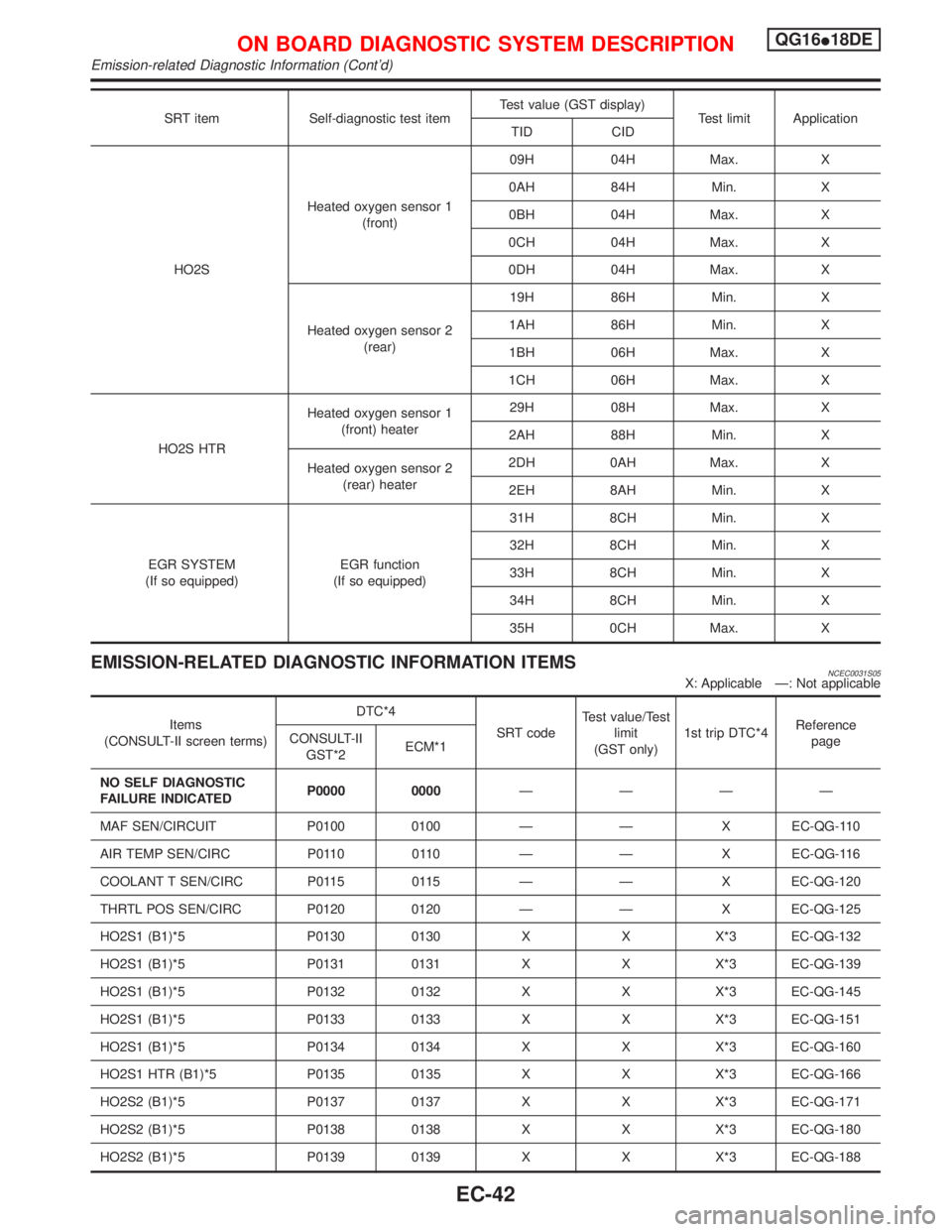
SRT item Self-diagnostic test itemTest value (GST display)
Test limit Application
TID CID
HO2SHeated oxygen sensor 1
(front)09H 04H Max. X
0AH 84H Min. X
0BH 04H Max. X
0CH 04H Max. X
0DH 04H Max. X
Heated oxygen sensor 2
(rear)19H 86H Min. X
1AH 86H Min. X
1BH 06H Max. X
1CH 06H Max. X
HO2S HTRHeated oxygen sensor 1
(front) heater29H 08H Max. X
2AH 88H Min. X
Heated oxygen sensor 2
(rear) heater2DH 0AH Max. X
2EH 8AH Min. X
EGR SYSTEM
(If so equipped)EGR function
(If so equipped)31H 8CH Min. X
32H 8CH Min. X
33H 8CH Min. X
34H 8CH Min. X
35H 0CH Max. X
EMISSION-RELATED DIAGNOSTIC INFORMATION ITEMSNCEC0031S05X: Applicable Ð: Not applicable
Items
(CONSULT-II screen terms)DTC*4
SRT codeTest value/Test
limit
(GST only)1st trip DTC*4Reference
page CONSULT-II
GST*2ECM*1
NO SELF DIAGNOSTIC
FAILURE INDICATEDP0000 0000ÐÐÐÐ
MAF SEN/CIRCUIT P0100 0100 Ð Ð X EC-QG-110
AIR TEMP SEN/CIRC P0110 0110 Ð Ð X EC-QG-116
COOLANT T SEN/CIRC P0115 0115 Ð Ð X EC-QG-120
THRTL POS SEN/CIRC P0120 0120 Ð Ð X EC-QG-125
HO2S1 (B1)*5 P0130 0130 X X X*3 EC-QG-132
HO2S1 (B1)*5 P0131 0131 X X X*3 EC-QG-139
HO2S1 (B1)*5 P0132 0132 X X X*3 EC-QG-145
HO2S1 (B1)*5 P0133 0133 X X X*3 EC-QG-151
HO2S1 (B1)*5 P0134 0134 X X X*3 EC-QG-160
HO2S1 HTR (B1)*5 P0135 0135 X X X*3 EC-QG-166
HO2S2 (B1)*5 P0137 0137 X X X*3 EC-QG-171
HO2S2 (B1)*5 P0138 0138 X X X*3 EC-QG-180
HO2S2 (B1)*5 P0139 0139 X X X*3 EC-QG-188
ON BOARD DIAGNOSTIC SYSTEM DESCRIPTIONQG16I18DE
Emission-related Diagnostic Information (Cont'd)
EC-42