Page 612 of 2267
4 CHECK HEATED OXYGEN SENSOR 1 HEATER (FRONT)
Refer to ªComponent Inspectionº, EC-QG-170.
OK or NG
OK©GO TO 5.
NG©Replace heated oxygen sensor 1 (front).
5 CHECK INTERMITTENT INCIDENT
Perform ªTROUBLE DIAGNOSIS FOR INTERMITTENT INCIDENTº, EC-QG-102.
©INSPECTION END
Component InspectionNLEC0143HEATED OXYGEN SENSOR 1 HEATER (FRONT)NLEC0143S01Check resistance between terminals 3 and 1.
Resistance: 2.3 - 4.3Wat 25ÉC (77ÉF)
Check continuity between terminals 2 and 1, 3 and 2.
Continuity should not exist.
If NG, replace the heated oxygen sensor 1 (front).
CAUTION:
IDiscard any heated oxygen sensor which has been
dropped from a height of more than 0.5 m (19.7 in) onto a
hard surface such as a concrete floor; use a new one.
IBefore installing new oxygen sensor, clean exhaust sys-
tem threads using Oxygen Sensor Thread Cleaner tool
and approved anti-seize lubricant.
SEF935X
DTC P0135 HEATED OXYGEN SENSOR 1 (FRONT)
HEATERQG16I18DE
Diagnostic Procedure (Cont'd)
EC-170
Page 645 of 2267

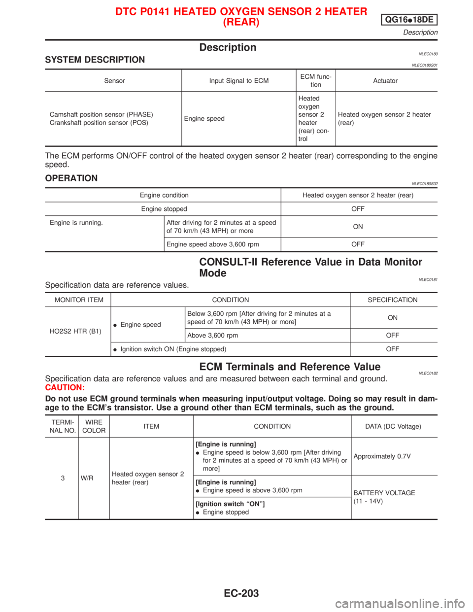
DescriptionNLEC0180SYSTEM DESCRIPTIONNLEC0180S01
Sensor Input Signal to ECMECM func-
tionActuator
Camshaft position sensor (PHASE)
Crankshaft position sensor (POS)Engine speedHeated
oxygen
sensor 2
heater
(rear) con-
trolHeated oxygen sensor 2 heater
(rear)
The ECM performs ON/OFF control of the heated oxygen sensor 2 heater (rear) corresponding to the engine
speed.
OPERATIONNLEC0180S02
Engine condition Heated oxygen sensor 2 heater (rear)
Engine stopped OFF
Engine is running. After driving for 2 minutes at a speed
of 70 km/h (43 MPH) or moreON
Engine speed above 3,600 rpm OFF
CONSULT-II Reference Value in Data Monitor
Mode
NLEC0181Specification data are reference values.
MONITOR ITEM CONDITION SPECIFICATION
HO2S2 HTR (B1)IEngine speedBelow 3,600 rpm [After driving for 2 minutes at a
speed of 70 km/h (43 MPH) or more]ON
Above 3,600 rpm OFF
IIgnition switch ON (Engine stopped) OFF
ECM Terminals and Reference ValueNLEC0182Specification data are reference values and are measured between each terminal and ground.
CAUTION:
Do not use ECM ground terminals when measuring input/output voltage. Doing so may result in dam-
age to the ECM's transistor. Use a ground other than ECM terminals, such as the ground.
TERMI-
NAL NO.WIRE
COLORITEM CONDITION DATA (DC Voltage)
3 W/RHeated oxygen sensor 2
heater (rear)[Engine is running]
IEngine speed is below 3,600 rpm [After driving
for 2 minutes at a speed of 70 km/h (43 MPH) or
more]Approximately 0.7V
[Engine is running]
IEngine speed is above 3,600 rpm
BATTERY VOLTAGE
(11 - 14V)
[Ignition switch ªONº]
IEngine stopped
DTC P0141 HEATED OXYGEN SENSOR 2 HEATER
(REAR)QG16I18DE
Description
EC-203
Page 646 of 2267

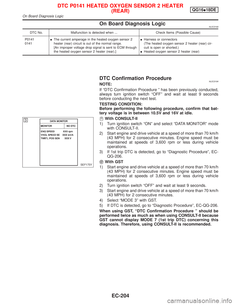
On Board Diagnosis LogicNLEC0183
DTC No. Malfunction is detected when ... Check Items (Possible Cause)
P0141
0141IThe current amperage in the heated oxygen sensor 2
heater (rear) circuit is out of the normal range.
[An improper voltage drop signal is sent to ECM through
the heated oxygen sensor 2 heater (rear).]IHarness or connectors
(The heated oxygen sensor 2 heater (rear) cir-
cuit is open or shorted.)
IHeated oxygen sensor 2 heater (rear)
DTC Confirmation ProcedureNLEC0184NOTE:
If ªDTC Confirmation Procedure º has been previously conducted,
always turn ignition switch ªOFFº and wait at least 9 seconds
before conducting the next test.
TESTING CONDITION:
Before performing the following procedure, confirm that bat-
tery voltage is in between 10.5V and 16V at idle.
With CONSULT-II
1) Turn ignition switch ªONº and select ªDATA MONITORº mode
with CONSULT-II.
2) Start engine and drive vehicle at a speed of more than 70 km/h
(43 MPH) for 2 consecutive minutes. Engine speed must be
maintained at speeds of 3,600 rpm or less during vehicle
operations.
3) If 1st trip DTC is detected, go to ªDiagnostic Procedureº, EC-
QG-206.
With GST
1) Start engine and drive vehicle at a speed of more than 70 km/h
(43 MPH) for 2 consecutive minutes. Engine speed must be
maintained at speeds of 3,600 rpm or less during vehicle
operations.
2) Turn ignition switch ªOFFº and wait at least 9 seconds.
3) Start engine and drive vehicle at a speed of more than 70 km/h
(43 MPH) for 2 consecutive minutes.
4) Select ªMODE 3º with GST.
5) If DTC is detected, go to ªDiagnostic Procedureº, EC-QG-206.
When using GST, ªDTC Confirmation Procedure º should be
performed twice as much as when using CONSULT-II because
GST cannot display MODE 7 (1st trip DTC) concerning this
diagnosis. Therefore, using CONSULT-II is recommended.SEF175Y
DTC P0141 HEATED OXYGEN SENSOR 2 HEATER
(REAR)QG16I18DE
On Board Diagnosis Logic
EC-204
Page 647 of 2267
Wiring DiagramNCEC0185
YEC068A
DTC P0141 HEATED OXYGEN SENSOR 2 HEATER
(REAR)QG16I18DE
Wiring Diagram
EC-205
Page 648 of 2267
Diagnostic ProcedureNCEC0186
1 CHECK POWER SUPPLY
1. Turn ignition switch ªOFFº.
2. Disconnect heated oxygen sensor 2 (rear) harness connector.
SEF033X3. Turn ignition switch ªONº.
4. Check voltage between terminal 4 and ground.
SEF047XVoltage: Battery voltage
OK or NG
OK©GO TO 3.
NG©GO TO 2.
2 DETECT MALFUNCTIONING PART
Check the following.
IHarness connectors F104, M50
IHarness for open or short between heated oxygen sensor 2 (rear) and fuse
I10A fuse
©Repair harness or connectors.
3 CHECK OUTPUT SIGNAL CIRCUIT
1. Turn ignition switch ªOFFº.
2. Disconnect ECM harness connector.
3. Check harness continuity between heated oxygen sensor 2 (rear) harness connector terminal 1 and ECM terminal 3.
Refer to wiring diagram.
Continuity should exist.
4. Also check harness for short to ground and short to power.
OK or NG
OK©GO TO 5.
NG©GO TO 4.
DTC P0141 HEATED OXYGEN SENSOR 2 HEATER
(REAR)QG16I18DE
Diagnostic Procedure
EC-206
Page 649 of 2267
5 CHECK HEATED OXYGEN SENSOR 2 HEATER (REAR)
Refer to ªComponent Inspectionº, EC-QG-207.
OK or NG
OK©GO TO 6.
NG©Replace heated oxygen sensor 2 (rear).
6 CHECK INTERMITTENT INCIDENT
Perform ªTROUBLE DIAGNOSIS FOR INTERMITTENT INCIDENTº, EC-QG-102.
©INSPECTION END
Component InspectionNLEC0187HEATED OXYGEN SENSOR 2 HEATER (REAR)NLEC0187S01Check the following.
1. Check resistance between terminals 1 and 4.
Resistance: 2.3 - 4.3Wat 25ÉC (77ÉF)
2. Check continuity.
Terminal No. Continuity
2 and 1, 3, 4
No
3 and 1, 2, 4
If NG, replace the heated oxygen sensor 2 (rear).
CAUTION:
IDiscard any heated oxygen sensor which has been
dropped from a height of more than 0.5 m (19.7 in) onto a
hard surface such as a concrete floor; use a new one.
IBefore installing new oxygen sensor, clean exhaust sys-
tem threads using Oxygen Sensor Thread Cleaner tool
and approved anti-seize lubricant.
SEF048X
DTC P0141 HEATED OXYGEN SENSOR 2 HEATER
(REAR)QG16I18DE
Diagnostic Procedure (Cont'd)
EC-207
Page 793 of 2267

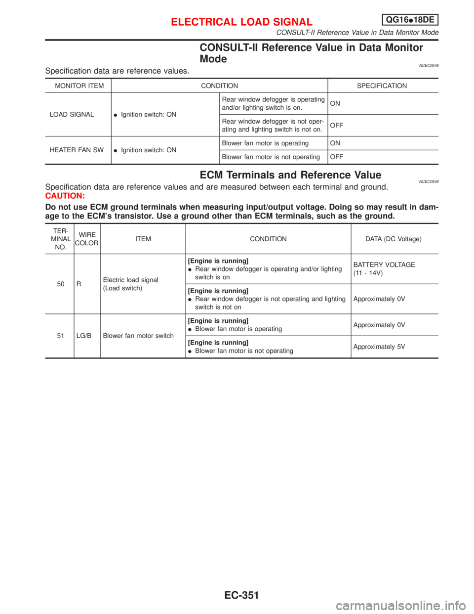
CONSULT-II Reference Value in Data Monitor
Mode
NCEC0548Specification data are reference values.
MONITOR ITEM CONDITION SPECIFICATION
LOAD SIGNALIIgnition switch: ONRear window defogger is operating
and/or lighting switch is on.ON
Rear window defogger is not oper-
ating and lighting switch is not on.OFF
HEATER FAN SWIIgnition switch: ONBlower fan motor is operating ON
Blower fan motor is not operating OFF
ECM Terminals and Reference ValueNCEC0549Specification data are reference values and are measured between each terminal and ground.
CAUTION:
Do not use ECM ground terminals when measuring input/output voltage. Doing so may result in dam-
age to the ECM's transistor. Use a ground other than ECM terminals, such as the ground.
TER-
MINAL
NO.WIRE
COLORITEM CONDITION DATA (DC Voltage)
50 RElectric load signal
(Load switch)[Engine is running]
IRear window defogger is operating and/or lighting
switch is onBATTERY VOLTAGE
(11 - 14V)
[Engine is running]
IRear window defogger is not operating and lighting
switch is not onApproximately 0V
51 LG/B Blower fan motor switch[Engine is running]
IBlower fan motor is operatingApproximately 0V
[Engine is running]
IBlower fan motor is not operatingApproximately 5V
ELECTRICAL LOAD SIGNALQG16I18DE
CONSULT-II Reference Value in Data Monitor Mode
EC-351
Page 797 of 2267

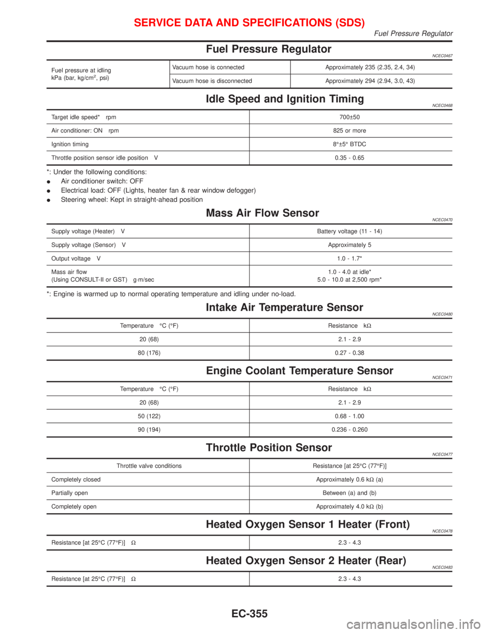
Fuel Pressure RegulatorNCEC0467
Fuel pressure at idling
kPa (bar, kg/cm2, psi)Vacuum hose is connected Approximately 235 (2.35, 2.4, 34)
Vacuum hose is disconnected Approximately 294 (2.94, 3.0, 43)
Idle Speed and Ignition TimingNCEC0468
Target idle speed* rpm700 50
Air conditioner: ON rpm825 or more
Ignition timing8É 5É BTDC
Throttle position sensor idle position V 0.35 - 0.65
*: Under the following conditions:
IAir conditioner switch: OFF
IElectrical load: OFF (Lights, heater fan & rear window defogger)
ISteering wheel: Kept in straight-ahead position
Mass Air Flow SensorNCEC0470
Supply voltage (Heater) VBattery voltage (11 - 14)
Supply voltage (Sensor) VApproximately 5
Output voltage V1.0 - 1.7*
Mass air flow
(Using CONSULT-II or GST) g×m/sec1.0 - 4.0 at idle*
5.0 - 10.0 at 2,500 rpm*
*: Engine is warmed up to normal operating temperature and idling under no-load.
Intake Air Temperature SensorNCEC0480
Temperature ÉC (ÉF) Resistance kW
20 (68) 2.1 - 2.9
80 (176) 0.27 - 0.38
Engine Coolant Temperature SensorNCEC0471
Temperature ÉC (ÉF) Resistance kW
20 (68) 2.1 - 2.9
50 (122) 0.68 - 1.00
90 (194) 0.236 - 0.260
Throttle Position SensorNCEC0477
Throttle valve conditions Resistance [at 25ÉC (77ÉF)]
Completely closedApproximately 0.6 kW(a)
Partially openBetween (a) and (b)
Completely openApproximately 4.0 kW(b)
Heated Oxygen Sensor 1 Heater (Front)NCEC0478
Resistance [at 25ÉC (77ÉF)]W2.3 - 4.3
Heated Oxygen Sensor 2 Heater (Rear)NCEC0483
Resistance [at 25ÉC (77ÉF)]W2.3 - 4.3
SERVICE DATA AND SPECIFICATIONS (SDS)
Fuel Pressure Regulator
EC-355