Page 1007 of 2267

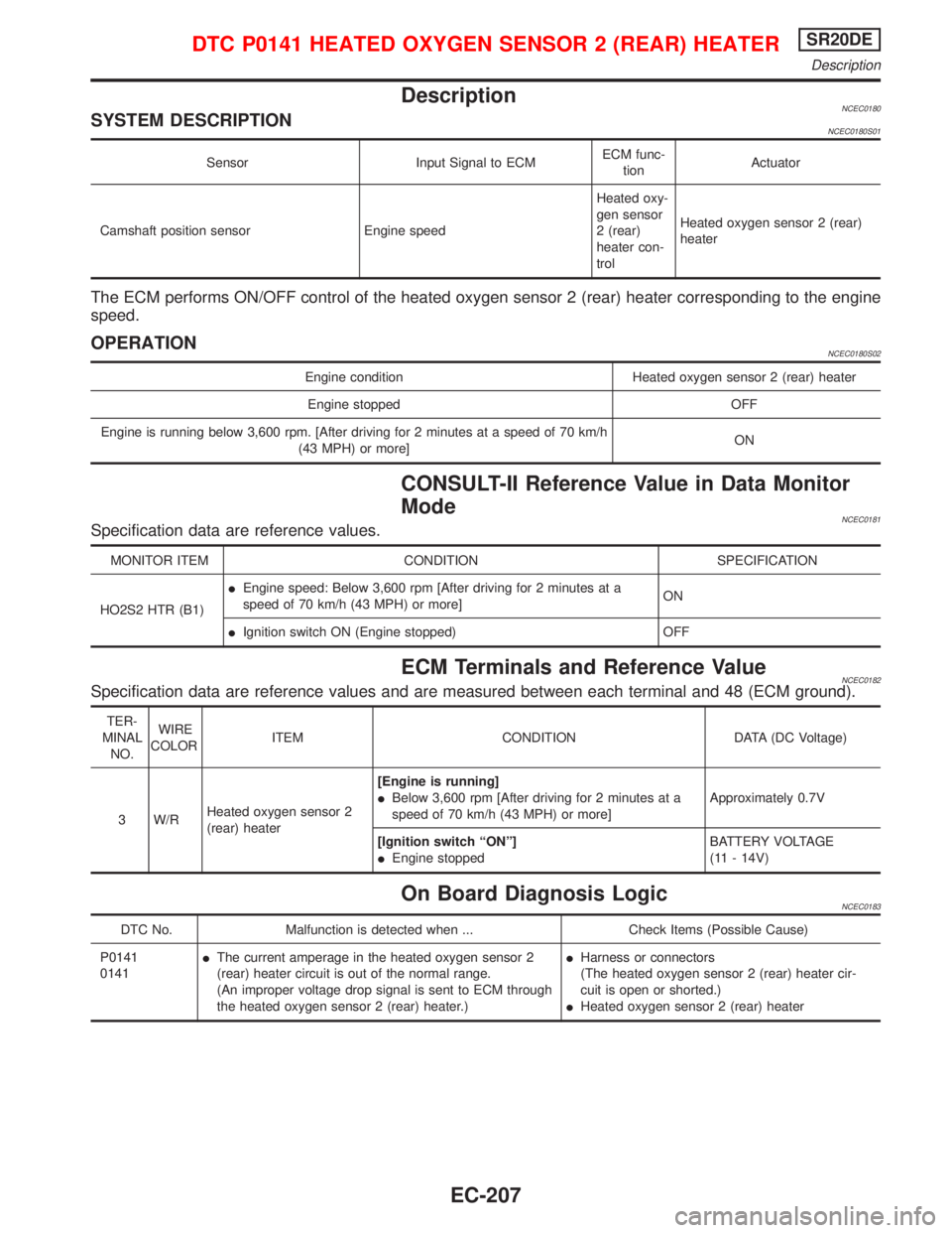
DescriptionNCEC0180SYSTEM DESCRIPTIONNCEC0180S01
Sensor Input Signal to ECMECM func-
tionActuator
Camshaft position sensor Engine speedHeated oxy-
gen sensor
2 (rear)
heater con-
trolHeated oxygen sensor 2 (rear)
heater
The ECM performs ON/OFF control of the heated oxygen sensor 2 (rear) heater corresponding to the engine
speed.
OPERATIONNCEC0180S02
Engine condition Heated oxygen sensor 2 (rear) heater
Engine stopped OFF
Engine is running below 3,600 rpm. [After driving for 2 minutes at a speed of 70 km/h
(43 MPH) or more]ON
CONSULT-II Reference Value in Data Monitor
Mode
NCEC0181Specification data are reference values.
MONITOR ITEM CONDITION SPECIFICATION
HO2S2 HTR (B1)IEngine speed: Below 3,600 rpm [After driving for 2 minutes at a
speed of 70 km/h (43 MPH) or more]ON
IIgnition switch ON (Engine stopped) OFF
ECM Terminals and Reference ValueNCEC0182Specification data are reference values and are measured between each terminal and 48 (ECM ground).
TER-
MINAL
NO.WIRE
COLORITEM CONDITION DATA (DC Voltage)
3 W/RHeated oxygen sensor 2
(rear) heater[Engine is running]
IBelow 3,600 rpm [After driving for 2 minutes at a
speed of 70 km/h (43 MPH) or more]Approximately 0.7V
[Ignition switch ªONº]
IEngine stoppedBATTERY VOLTAGE
(11 - 14V)
On Board Diagnosis LogicNCEC0183
DTC No. Malfunction is detected when ... Check Items (Possible Cause)
P0141
0141IThe current amperage in the heated oxygen sensor 2
(rear) heater circuit is out of the normal range.
(An improper voltage drop signal is sent to ECM through
the heated oxygen sensor 2 (rear) heater.)IHarness or connectors
(The heated oxygen sensor 2 (rear) heater cir-
cuit is open or shorted.)
IHeated oxygen sensor 2 (rear) heater
DTC P0141 HEATED OXYGEN SENSOR 2 (REAR) HEATERSR20DE
Description
EC-207
Page 1008 of 2267

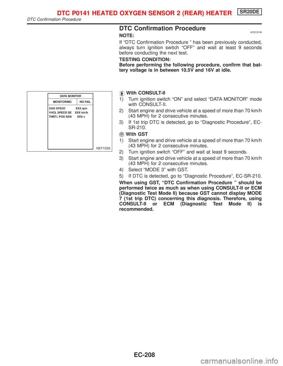
DTC Confirmation ProcedureNCEC0184NOTE:
If ªDTC Confirmation Procedure º has been previously conducted,
always turn ignition switch ªOFFº and wait at least 9 seconds
before conducting the next test.
TESTING CONDITION:
Before performing the following procedure, confirm that bat-
tery voltage is in between 10.5V and 16V at idle.
With CONSULT-II
1) Turn ignition switch ªONº and select ªDATA MONITORº mode
with CONSULT-II.
2) Start engine and drive vehicle at a speed of more than 70 km/h
(43 MPH) for 2 consecutive minutes.
3) If 1st trip DTC is detected, go to ªDiagnostic Procedureº, EC-
SR-210.
With GST
1) Start engine and drive vehicle at a speed of more than 70 km/h
(43 MPH) for 2 consecutive minutes.
2) Turn ignition switch ªOFFº and wait at least 9 seconds.
3) Start engine and drive vehicle at a speed of more than 70 km/h
(43 MPH) for 2 consecutive minutes.
4) Select ªMODE 3º with GST.
5) If DTC is detected, go to ªDiagnostic Procedureº, EC-SR-210.
When using GST, ªDTC Confirmation Procedure º should be
performed twice as much as when using CONSULT-II or ECM
(Diagnostic Test Mode II) because GST cannot display MODE
7 (1st trip DTC) concerning this diagnosis. Therefore, using
CONSULT-II or ECM (Diagnostic Test Mode II) is
recommended.
NEF103A
DTC P0141 HEATED OXYGEN SENSOR 2 (REAR) HEATERSR20DE
DTC Confirmation Procedure
EC-208
Page 1009 of 2267
Wiring DiagramNCEC0185
YEC087A
DTC P0141 HEATED OXYGEN SENSOR 2 (REAR) HEATERSR20DE
Wiring Diagram
EC-209
Page 1010 of 2267

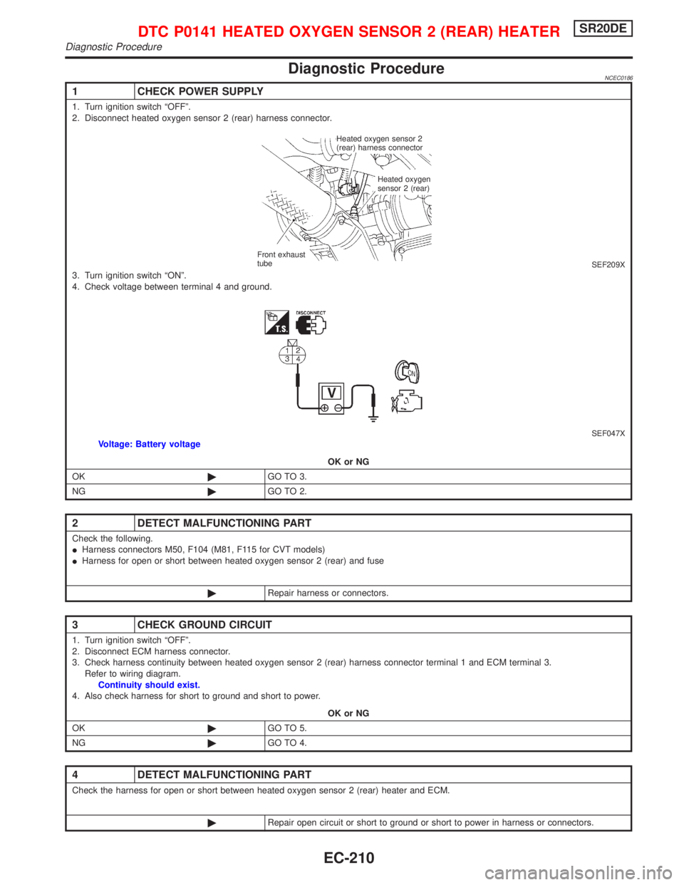
Diagnostic ProcedureNCEC0186
1 CHECK POWER SUPPLY
1. Turn ignition switch ªOFFº.
2. Disconnect heated oxygen sensor 2 (rear) harness connector.
SEF209X3. Turn ignition switch ªONº.
4. Check voltage between terminal 4 and ground.
SEF047XVoltage: Battery voltage
OK or NG
OK©GO TO 3.
NG©GO TO 2.
2 DETECT MALFUNCTIONING PART
Check the following.
IHarness connectors M50, F104 (M81, F115 for CVT models)
IHarness for open or short between heated oxygen sensor 2 (rear) and fuse
©Repair harness or connectors.
3 CHECK GROUND CIRCUIT
1. Turn ignition switch ªOFFº.
2. Disconnect ECM harness connector.
3. Check harness continuity between heated oxygen sensor 2 (rear) harness connector terminal 1 and ECM terminal 3.
Refer to wiring diagram.
Continuity should exist.
4. Also check harness for short to ground and short to power.
OK or NG
OK©GO TO 5.
NG©GO TO 4.
4 DETECT MALFUNCTIONING PART
Check the harness for open or short between heated oxygen sensor 2 (rear) heater and ECM.
©Repair open circuit or short to ground or short to power in harness or connectors.
Heated oxygen sensor 2
(rear) harness connector
Heated oxygen
sensor 2 (rear)
Front exhaust
tube
DTC P0141 HEATED OXYGEN SENSOR 2 (REAR) HEATERSR20DE
Diagnostic Procedure
EC-210
Page 1011 of 2267
Component InspectionNCEC0187HEATED OXYGEN SENSOR 2 (REAR) HEATERNCEC0187S01Check the following.
1. Check resistance between terminals 1 and 4.
Resistance: 2.3 - 4.3Wat 25ÉC (77ÉF)
2. Check continuity.
Terminal No. Continuity
2 and 1, 3, 4
No
3 and 1, 2, 4
If NG, replace the heated oxygen sensor 2 (rear).
CAUTION:
Discard any heated oxygen sensor which has been dropped
from a height of more than 0.5 m (19.7 in) onto a hard surface
such as a concrete floor; use a new one.
5 CHECK HEATED OXYGEN SENSOR 2 (REAR) HEATER
Refer to ªComponent Inspectionº, EC-SR-211.
OK or NG
OK©GO TO 6.
NG©Replace heated oxygen sensor 2 (rear).
6 CHECK INTERMITTENT INCIDENT
Perform ªTROUBLE DIAGNOSIS FOR INTERMITTENT INCIDENTº, EC-SR-114.
©INSPECTION END
SEF048X
DTC P0141 HEATED OXYGEN SENSOR 2 (REAR) HEATERSR20DE
Component Inspection
EC-211
Page 1125 of 2267
CONSULT-II Reference Value in Data Monitor
Mode
NCEC0548Specification data are reference values.
MONITOR ITEM CONDITION SPECIFICATION
LOAD SIGNALIEngine: runningRear window defogger or head-
lamp ªONºON
Except the above OFF
HEATER FAN SWIIgnition switch: ONHeater fan switch: ON ON
Heater fan switch: OFF OFF
ECM Terminals and Reference ValueNCEC0549Specification data are reference values and are measured between each terminal and 48 (ECM ground).
TER-
MINAL
NO.WIRE
COLORITEM CONDITION DATA (DC Voltage)
50 R Electric load signal[Engine is running]
IHeadlamp switch or rear window defogger switch
is ªONºBATTERY VOLTAGE
(11 - 14V)
51 LG/B Blower fan SW[Ignition switch ªONº]
IBlower fan switch is ªONºApproximately 0V
[Ignition switch ªONº]
IBlower fan switch is ªOFFºApproximately 5V
ELECTRICAL LOAD SIGNALSR20DE
CONSULT-II Reference Value in Data Monitor Mode
EC-325
Page 1130 of 2267

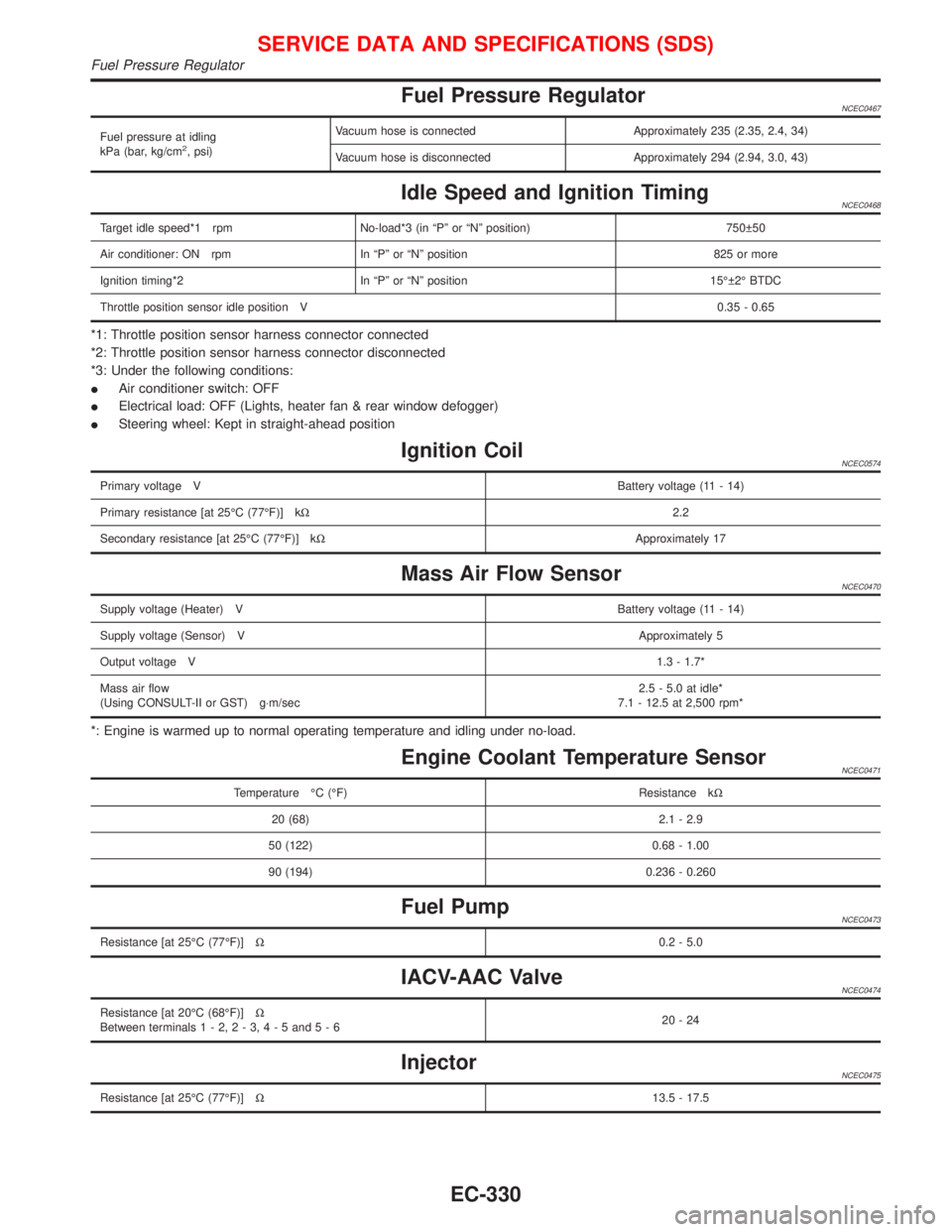
Fuel Pressure RegulatorNCEC0467
Fuel pressure at idling
kPa (bar, kg/cm2, psi)Vacuum hose is connected Approximately 235 (2.35, 2.4, 34)
Vacuum hose is disconnected Approximately 294 (2.94, 3.0, 43)
Idle Speed and Ignition TimingNCEC0468
Target idle speed*1 rpm No-load*3 (in ªPº or ªNº position) 750 50
Air conditioner: ON rpm In ªPº or ªNº position 825 or more
Ignition timing*2 In ªPº or ªNº position 15É 2É BTDC
Throttle position sensor idle position V0.35 - 0.65
*1: Throttle position sensor harness connector connected
*2: Throttle position sensor harness connector disconnected
*3: Under the following conditions:
IAir conditioner switch: OFF
IElectrical load: OFF (Lights, heater fan & rear window defogger)
ISteering wheel: Kept in straight-ahead position
Ignition CoilNCEC0574
Primary voltage VBattery voltage (11 - 14)
Primary resistance [at 25ÉC (77ÉF)] kW2.2
Secondary resistance [at 25ÉC (77ÉF)] kWApproximately 17
Mass Air Flow SensorNCEC0470
Supply voltage (Heater) VBattery voltage (11 - 14)
Supply voltage (Sensor) VApproximately 5
Output voltage V1.3 - 1.7*
Mass air flow
(Using CONSULT-II or GST) g×m/sec2.5 - 5.0 at idle*
7.1 - 12.5 at 2,500 rpm*
*: Engine is warmed up to normal operating temperature and idling under no-load.
Engine Coolant Temperature SensorNCEC0471
Temperature ÉC (ÉF) Resistance kW
20 (68) 2.1 - 2.9
50 (122) 0.68 - 1.00
90 (194) 0.236 - 0.260
Fuel PumpNCEC0473
Resistance [at 25ÉC (77ÉF)]W0.2 - 5.0
IACV-AAC ValveNCEC0474
Resistance [at 20ÉC (68ÉF)]W
Between terminals1-2,2-3,4-5and5-620-24
InjectorNCEC0475
Resistance [at 25ÉC (77ÉF)]W13.5 - 17.5
SERVICE DATA AND SPECIFICATIONS (SDS)
Fuel Pressure Regulator
EC-330
Page 1131 of 2267
Throttle Position SensorNCEC0477
Throttle valve conditions Resistance [at 25ÉC (77ÉF)]
Completely closedApproximately 0.6 kW
Partially open0.6 - 4.0 kW
Completely openApproximately 4.0 kW
Heated Oxygen Sensor 1 (Front) HeaterNCEC0478
Resistance [at 25ÉC (77ÉF)]W2.3 - 4.3
Intake Air Temperature SensorNCEC0480
Temperature ÉC (ÉF) Resistance kW
20 (68) 2.2 - 2.6
80 (176) 0.31 - 0.37
EVAP Canister Purge Volume Control ValveNCEC0481
Resistance [at 20ÉC (68ÉF)]W31-35
Heated Oxygen Sensor 1 (Rear) HeaterNCEC0483
Resistance [at 25ÉC (77ÉF)]W2.3 - 4.3
Crankshaft Position Sensor (OBD)NCEC0575
Resistance [at 25ÉC (77ÉF)]W166 - 204
SERVICE DATA AND SPECIFICATIONS (SDS)
Throttle Position Sensor
EC-331