1999 NISSAN PRIMERA check engine light
[x] Cancel search: check engine lightPage 20 of 2267
HOW TO ERASE DTC (WITH GST)NCAT0020S041. If the ignition switch stays ªONº after repair work, be sure to turn ignition switch ªOFFº once. Wait at least
5 seconds and then turn it ªONº (engine stopped) again.
2. Perform ªOBD SELF-DIAGNOSTIC PROCEDURE (No Tools)º. Refer to AT-25. (The engine warm-up step
can be skipped when performing the diagnosis only to erase the DTC.)
3. Select Mode 4 with Generic Scan Tool (GST). For details, refer to EC section ªGeneric Scan Tool (GST)º.
HOW TO ERASE DTC (NO TOOLS)NCAT0020S051. If the ignition switch stays ªONº after repair work, be sure to turn ignition switch ªOFFº once. Wait at least
5 seconds and then turn it ªONº (engine stopped) again.
2. Perform ªTCM SELF-DIAGNOSTIC PROCEDURE (No Tools)º. Refer to AT-25. (The engine warm-up step
can be skipped when performing the diagnosis only to erase the DTC.)
3. Change the diagnostic test mode from Mode II to Mode I by turning the mode selector on the ECM.
Refer to EC section ªHOW TO SWITCH DIAGNOSTIC TEST MODESº.
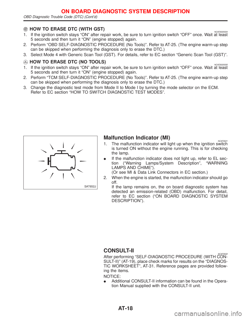
Malfunction Indicator (MI)NCAT00211. The malfunction indicator will light up when the ignition switch
is turned ON without the engine running. This is for checking
the lamp.
IIf the malfunction indicator does not light up, refer to EL sec-
tion (ªWarning Lamps/System Descriptionº, ªWARNING
LAMPS AND CHIMEº).
(Or see MI & Data Link Connectors in EC section.)
2. When the engine is started, the malfunction indicator should go
off.
If the lamp remains on, the on board diagnostic system has
detected an emission-related (OBD) malfunction. For detail,
refer to EC section (ªON BOARD DIAGNOSTIC SYSTEM
DESCRIPTIONº).
CONSULT-IINCAT0022After performing ªSELF-DIAGNOSTIC PROCEDURE (WITH CON-
SULT-II)º (AT-19), place check marks for results on the ªDIAGNOS-
TIC WORKSHEETº, AT-31. Reference pages are provided follow-
ing the items.
NOTICE:
IAdditional CONSULT-II information can be found in the Opera-
tion Manual supplied with the CONSULT-II unit.
SAT652J
ON BOARD DIAGNOSTIC SYSTEM DESCRIPTION
OBD Diagnostic Trouble Code (DTC) (Cont'd)
AT-18
Page 36 of 2267
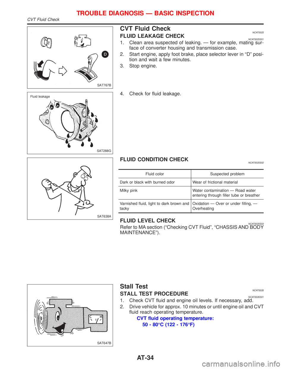
CVT Fluid CheckNCAT0025FLUID LEAKAGE CHECKNCAT0025S011. Clean area suspected of leaking. Ð for example, mating sur-
face of converter housing and transmission case.
2. Start engine, apply foot brake, place selector lever in ªDº posi-
tion and wait a few minutes.
3. Stop engine.
4. Check for fluid leakage.
FLUID CONDITION CHECKNCAT0025S02
Fluid color Suspected problem
Dark or black with burned odor Wear of frictional material
Milky pink Water contamination Ð Road water
entering through filler tube or breather
Varnished fluid, light to dark brown and
tackyOxidation Ð Over or under filling, Ð
Overheating
FLUID LEVEL CHECKNCAT0025S03Refer to MA section (ªChecking CVT Fluidº, ªCHASSIS AND BODY
MAINTENANCEº).
Stall TestNCAT0026STALL TEST PROCEDURENCAT0026S011. Check CVT fluid and engine oil levels. If necessary, add.
2. Drive vehicle for approx. 10 minutes or until engine oil and CVT
fluid reach operating temperature.
CVT fluid operating temperature:
50 - 80ÉC (122 - 176ÉF)
SAT767B
SAT288G Fluid leakage
SAT638A
SAT647B
TROUBLE DIAGNOSIS Ð BASIC INSPECTION
CVT Fluid Check
AT-34
Page 101 of 2267
Description
ªCVT SAFE FUNCTIONº is function to protect CVT.
ON BOARD DIAGNOSIS LOGIC
Diagnostic trouble code Malfunction is detected when ... Check items (Possible cause)
: CVT SAFE FUNCTION
TCM is malfunctioning TCM
: 10th judgement flicker
DIAGNOSTIC TROUBLE CODE (DTC) CONFIRMATION
PROCEDURE
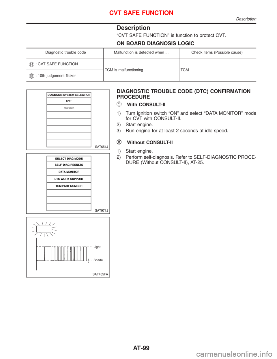
With CONSULT-II
1) Turn ignition switch ªONº and select ªDATA MONITORº mode
for CVT with CONSULT-II.
2) Start engine.
3) Run engine for at least 2 seconds at idle speed.
Without CONSULT-II
1) Start engine.
2) Perform self-diagnosis. Refer to SELF-DIAGNOSTIC PROCE-
DURE (Without CONSULT-II), AT-25.SAT651J
SAT971J
SAT455FALight
Shade
CVT SAFE FUNCTION
Description
AT-99
Page 119 of 2267
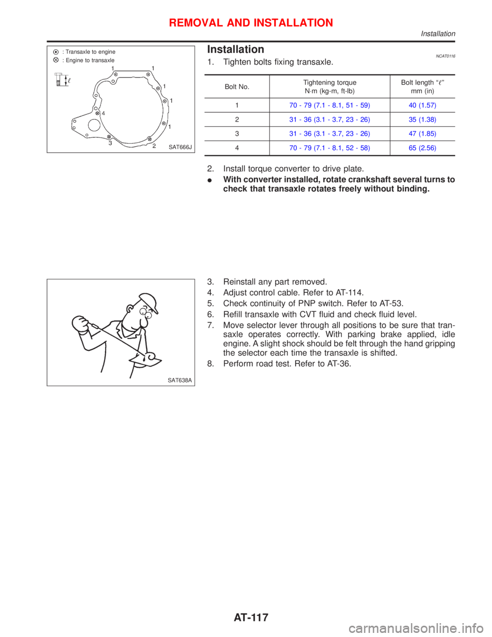
InstallationNCAT01161. Tighten bolts fixing transaxle.
Bolt No.Tightening torque
N×m (kg-m, ft-lb)Bolt length ªº
mm (in)
170 - 79 (7.1 - 8.1, 51 - 59) 40 (1.57)
231 - 36 (3.1 - 3.7, 23 - 26) 35 (1.38)
331 - 36 (3.1 - 3.7, 23 - 26) 47 (1.85)
470 - 79 (7.1 - 8.1, 52 - 58) 65 (2.56)
2. Install torque converter to drive plate.
IWith converter installed, rotate crankshaft several turns to
check that transaxle rotates freely without binding.
3. Reinstall any part removed.
4. Adjust control cable. Refer to AT-114.
5. Check continuity of PNP switch. Refer to AT-53.
6. Refill transaxle with CVT fluid and check fluid level.
7. Move selector lever through all positions to be sure that tran-
saxle operates correctly. With parking brake applied, idle
engine. A slight shock should be felt through the hand gripping
the selector each time the transaxle is shifted.
8. Perform road test. Refer to AT-36.
SAT666J : Transaxle to engine
: Engine to transaxle
SAT638A
REMOVAL AND INSTALLATION
Installation
AT-117
Page 140 of 2267
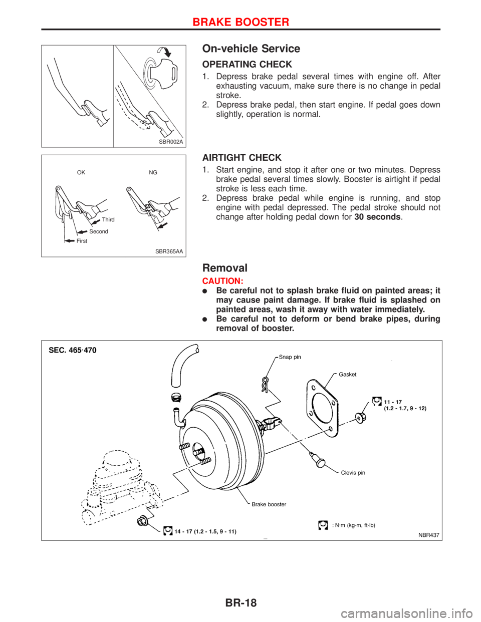
On-vehicle Service
OPERATING CHECK
1. Depress brake pedal several times with engine off. After
exhausting vacuum, make sure there is no change in pedal
stroke.
2. Depress brake pedal, then start engine. If pedal goes down
slightly, operation is normal.
AIRTIGHT CHECK
1. Start engine, and stop it after one or two minutes. Depress
brake pedal several times slowly. Booster is airtight if pedal
stroke is less each time.
2. Depress brake pedal while engine is running, and stop
engine with pedal depressed. The pedal stroke should not
change after holding pedal down for30 seconds.
Removal
CAUTION:
lBe careful not to splash brake fluid on painted areas; it
may cause paint damage. If brake fluid is splashed on
painted areas, wash it away with water immediately.
lBe careful not to deform or bend brake pipes, during
removal of booster.
SBR002A
SBR365AA OK NG
Third
Second
First
NBR437
BRAKE BOOSTER
BR-18
Page 292 of 2267
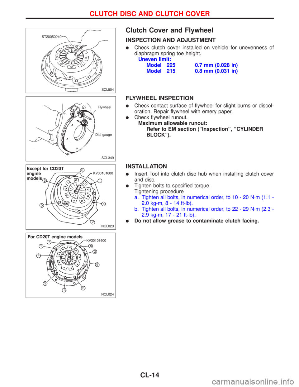
Clutch Cover and Flywheel
INSPECTION AND ADJUSTMENT
lCheck clutch cover installed on vehicle for unevenness of
diaphragm spring toe height.
Uneven limit:
Model 225 0.7 mm (0.028 in)
Model 215 0.8 mm (0.031 in)
FLYWHEEL INSPECTION
lCheck contact surface of flywheel for slight burns or discol-
oration. Repair flywheel with emery paper.
lCheck flywheel runout.
Maximum allowable runout:
Refer to EM section (ªInspectionº, ªCYLINDER
BLOCKº).
INSTALLATION
lInsert Tool into clutch disc hub when installing clutch cover
and disc.
lTighten bolts to specified torque.
Tightening procedure
a. Tighten all bolts, in numerical order, to 10 - 20 N´m (1.1 -
2.0 kg-m,8-14ft-lb).
b. Tighten all bolts, in numerical order, to 22 - 29 N´m (2.3 -
2.9 kg-m, 17 - 21 ft-lb).
lDo not allow grease to contaminate clutch facing.
SCL504
SCL349 Flywheel
Dial gauge
NCL023
Except for CD20T
engine
models6
1 KV30101600
4
2 53
NCL024 KV30101600
For CD20T engine models
1
2
3 45
6 7
8
9
CLUTCH DISC AND CLUTCH COVER
CL-14
Page 334 of 2267
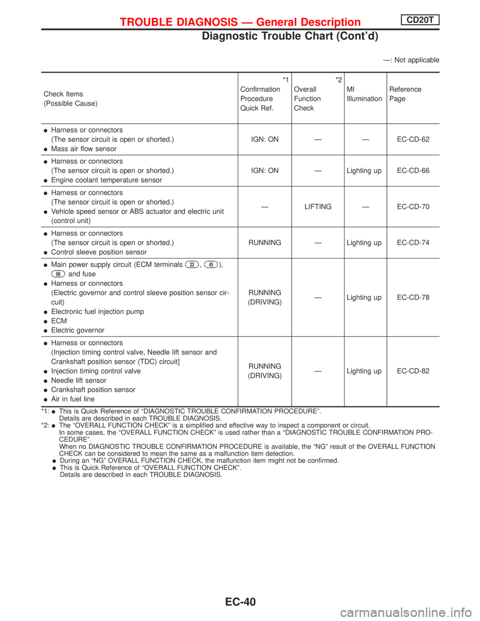
Ð: Not applicable
Check Items
(Possible Cause)*1
Confirmation
Procedure
Quick Ref.*2
Overall
Function
CheckMI
IlluminationReference
Page
lHarness or connectors
(The sensor circuit is open or shorted.)
lMass air flow sensorIGN: ON Ð Ð EC-CD-62
lHarness or connectors
(The sensor circuit is open or shorted.)
lEngine coolant temperature sensorIGN: ON Ð Lighting up EC-CD-66
lHarness or connectors
(The sensor circuit is open or shorted.)
lVehicle speed sensor or ABS actuator and electric unit
(control unit)Ð LIFTING Ð EC-CD-70
lHarness or connectors
(The sensor circuit is open or shorted.)
lControl sleeve position sensorRUNNING Ð Lighting up EC-CD-74
lMain power supply circuit (ECM terminals23,45),
68and fuse
lHarness or connectors
(Electric governor and control sleeve position sensor cir-
cuit)
lElectronic fuel injection pump
lECM
lElectric governorRUNNING
(DRIVING)Ð Lighting up EC-CD-78
lHarness or connectors
(Injection timing control valve, Needle lift sensor and
Crankshaft position sensor (TDC) circuit]
lInjection timing control valve
lNeedle lift sensor
lCrankshaft position sensor
lAir in fuel lineRUNNING
(DRIVING)Ð Lighting up EC-CD-82
*1:lThis is Quick Reference of ªDIAGNOSTIC TROUBLE CONFIRMATION PROCEDUREº.
Details are described in each TROUBLE DIAGNOSIS.
*2:
lThe ªOVERALL FUNCTION CHECKº is a simplified and effective way to inspect a component or circuit.
In some cases, the ªOVERALL FUNCTION CHECKº is used rather than a ªDIAGNOSTIC TROUBLE CONFIRMATION PRO-
CEDUREº.
When no DIAGNOSTIC TROUBLE CONFIRMATION PROCEDURE is available, the ªNGº result of the OVERALL FUNCTION
CHECK can be considered to mean the same as a malfunction item detection.
lDuring an ªNGº OVERALL FUNCTION CHECK, the malfunction item might not be confirmed.lThis is Quick Reference of ªOVERALL FUNCTION CHECKº.
Details are described in each TROUBLE DIAGNOSIS.
TROUBLE DIAGNOSIS Ð General DescriptionCD20T
Diagnostic Trouble Chart (Cont'd)
EC-40
Page 336 of 2267
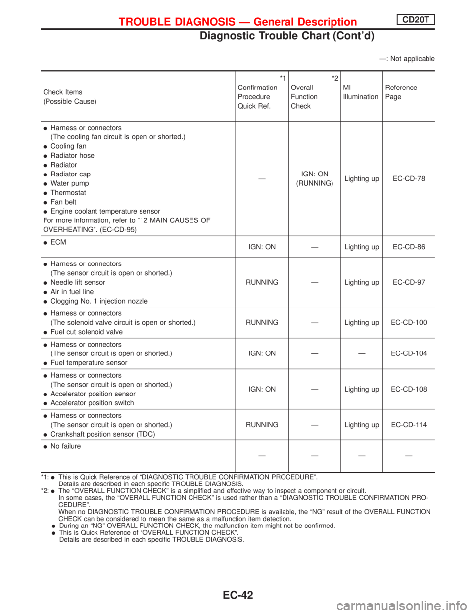
Ð: Not applicable
Check Items
(Possible Cause)*1
Confirmation
Procedure
Quick Ref.*2
Overall
Function
CheckMI
IlluminationReference
Page
lHarness or connectors
(The cooling fan circuit is open or shorted.)
lCooling fan
lRadiator hose
lRadiator
lRadiator cap
lWater pump
lThermostat
lFan belt
lEngine coolant temperature sensor
For more information, refer to ª12 MAIN CAUSES OF
OVERHEATINGº. (EC-CD-95)ÐIGN: ON
(RUNNING)Lighting up EC-CD-78
lECM
IGN: ON Ð Lighting up EC-CD-86
lHarness or connectors
(The sensor circuit is open or shorted.)
lNeedle lift sensor
lAir in fuel line
lClogging No. 1 injection nozzleRUNNING Ð Lighting up EC-CD-97
lHarness or connectors
(The solenoid valve circuit is open or shorted.)
lFuel cut solenoid valveRUNNING Ð Lighting up EC-CD-100
lHarness or connectors
(The sensor circuit is open or shorted.)
lFuel temperature sensorIGN: ON Ð Ð EC-CD-104
lHarness or connectors
(The sensor circuit is open or shorted.)
lAccelerator position sensor
lAccelerator position switchIGN: ON Ð Lighting up EC-CD-108
lHarness or connectors
(The sensor circuit is open or shorted.)
lCrankshaft position sensor (TDC)RUNNING Ð Lighting up EC-CD-114
lNo failure
Ð ÐÐÐ
*1:lThis is Quick Reference of ªDIAGNOSTIC TROUBLE CONFIRMATION PROCEDUREº.
Details are described in each specific TROUBLE DIAGNOSIS.
*2:
lThe ªOVERALL FUNCTION CHECKº is a simplified and effective way to inspect a component or circuit.
In some cases, the ªOVERALL FUNCTION CHECKº is used rather than a ªDIAGNOSTIC TROUBLE CONFIRMATION PRO-
CEDUREº.
When no DIAGNOSTIC TROUBLE CONFIRMATION PROCEDURE is available, the ªNGº result of the OVERALL FUNCTION
CHECK can be considered to mean the same as a malfunction item detection.
lDuring an ªNGº OVERALL FUNCTION CHECK, the malfunction item might not be confirmed.lThis is Quick Reference of ªOVERALL FUNCTION CHECKº.
Details are described in each specific TROUBLE DIAGNOSIS.
TROUBLE DIAGNOSIS Ð General DescriptionCD20T
Diagnostic Trouble Chart (Cont'd)
EC-42