1999 NISSAN PRIMERA check engine
[x] Cancel search: check enginePage 3 of 2267
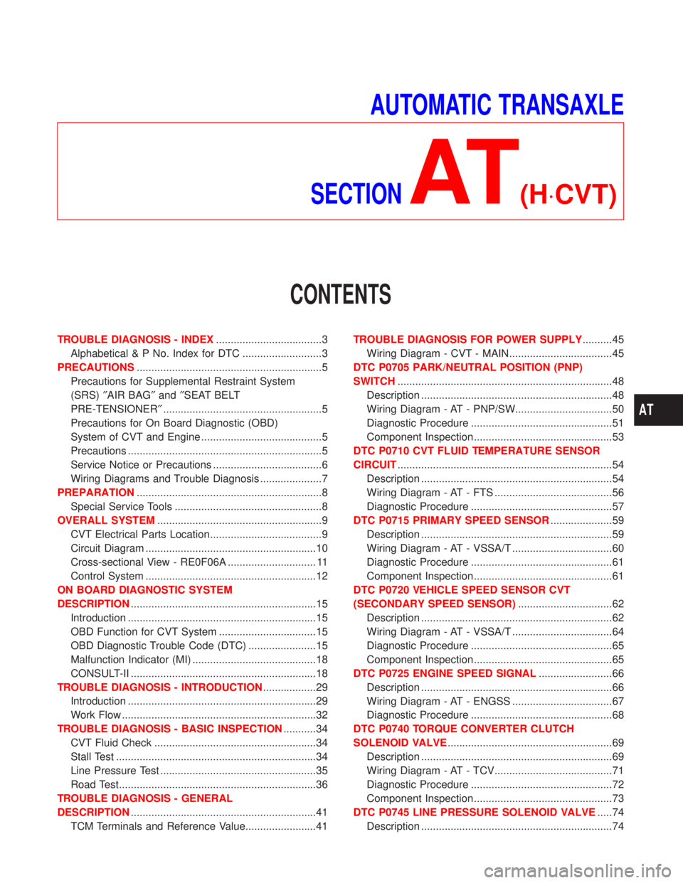
AUTOMATIC TRANSAXLE
SECTION
AT(H×CVT)
CONTENTS
TROUBLE DIAGNOSIS - INDEX....................................3
Alphabetical & P No. Index for DTC ...........................3
PRECAUTIONS...............................................................5
Precautions for Supplemental Restraint System
(SRS)²AIR BAG²and²SEAT BELT
PRE-TENSIONER²......................................................5
Precautions for On Board Diagnostic (OBD)
System of CVT and Engine .........................................5
Precautions ..................................................................5
Service Notice or Precautions .....................................6
Wiring Diagrams and Trouble Diagnosis .....................7
PREPARATION...............................................................8
Special Service Tools ..................................................8
OVERALL SYSTEM........................................................9
CVT Electrical Parts Location......................................9
Circuit Diagram ..........................................................10
Cross-sectional View - RE0F06A .............................. 11
Control System ..........................................................12
ON BOARD DIAGNOSTIC SYSTEM
DESCRIPTION...............................................................15
Introduction ................................................................15
OBD Function for CVT System .................................15
OBD Diagnostic Trouble Code (DTC) .......................15
Malfunction Indicator (MI) ..........................................18
CONSULT-II ...............................................................18
TROUBLE DIAGNOSIS - INTRODUCTION..................29
Introduction ................................................................29
Work Flow ..................................................................32
TROUBLE DIAGNOSIS - BASIC INSPECTION...........34
CVT Fluid Check .......................................................34
Stall Test ....................................................................34
Line Pressure Test .....................................................35
Road Test...................................................................36
TROUBLE DIAGNOSIS - GENERAL
DESCRIPTION...............................................................41
TCM Terminals and Reference Value........................41TROUBLE DIAGNOSIS FOR POWER SUPPLY..........45
Wiring Diagram - CVT - MAIN...................................45
DTC P0705 PARK/NEUTRAL POSITION (PNP)
SWITCH.........................................................................48
Description .................................................................48
Wiring Diagram - AT - PNP/SW.................................50
Diagnostic Procedure ................................................51
Component Inspection ...............................................53
DTC P0710 CVT FLUID TEMPERATURE SENSOR
CIRCUIT.........................................................................54
Description .................................................................54
Wiring Diagram - AT - FTS ........................................56
Diagnostic Procedure ................................................57
DTC P0715 PRIMARY SPEED SENSOR.....................59
Description .................................................................59
Wiring Diagram - AT - VSSA/T ..................................60
Diagnostic Procedure ................................................61
Component Inspection ...............................................61
DTC P0720 VEHICLE SPEED SENSOR CVT
(SECONDARY SPEED SENSOR)................................62
Description .................................................................62
Wiring Diagram - AT - VSSA/T ..................................64
Diagnostic Procedure ................................................65
Component Inspection ...............................................65
DTC P0725 ENGINE SPEED SIGNAL.........................66
Description .................................................................66
Wiring Diagram - AT - ENGSS ..................................67
Diagnostic Procedure ................................................68
DTC P0740 TORQUE CONVERTER CLUTCH
SOLENOID VALVE........................................................69
Description .................................................................69
Wiring Diagram - AT - TCV........................................71
Diagnostic Procedure ................................................72
Component Inspection ...............................................73
DTC P0745 LINE PRESSURE SOLENOID VALVE.....74
Description .................................................................74
AT
Page 20 of 2267
HOW TO ERASE DTC (WITH GST)NCAT0020S041. If the ignition switch stays ªONº after repair work, be sure to turn ignition switch ªOFFº once. Wait at least
5 seconds and then turn it ªONº (engine stopped) again.
2. Perform ªOBD SELF-DIAGNOSTIC PROCEDURE (No Tools)º. Refer to AT-25. (The engine warm-up step
can be skipped when performing the diagnosis only to erase the DTC.)
3. Select Mode 4 with Generic Scan Tool (GST). For details, refer to EC section ªGeneric Scan Tool (GST)º.
HOW TO ERASE DTC (NO TOOLS)NCAT0020S051. If the ignition switch stays ªONº after repair work, be sure to turn ignition switch ªOFFº once. Wait at least
5 seconds and then turn it ªONº (engine stopped) again.
2. Perform ªTCM SELF-DIAGNOSTIC PROCEDURE (No Tools)º. Refer to AT-25. (The engine warm-up step
can be skipped when performing the diagnosis only to erase the DTC.)
3. Change the diagnostic test mode from Mode II to Mode I by turning the mode selector on the ECM.
Refer to EC section ªHOW TO SWITCH DIAGNOSTIC TEST MODESº.
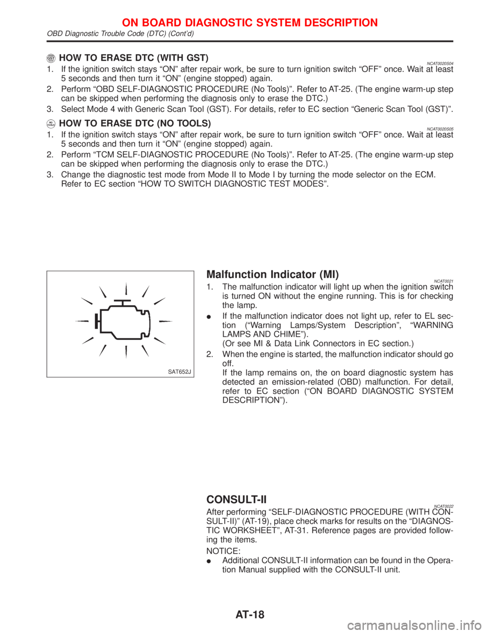
Malfunction Indicator (MI)NCAT00211. The malfunction indicator will light up when the ignition switch
is turned ON without the engine running. This is for checking
the lamp.
IIf the malfunction indicator does not light up, refer to EL sec-
tion (ªWarning Lamps/System Descriptionº, ªWARNING
LAMPS AND CHIMEº).
(Or see MI & Data Link Connectors in EC section.)
2. When the engine is started, the malfunction indicator should go
off.
If the lamp remains on, the on board diagnostic system has
detected an emission-related (OBD) malfunction. For detail,
refer to EC section (ªON BOARD DIAGNOSTIC SYSTEM
DESCRIPTIONº).
CONSULT-IINCAT0022After performing ªSELF-DIAGNOSTIC PROCEDURE (WITH CON-
SULT-II)º (AT-19), place check marks for results on the ªDIAGNOS-
TIC WORKSHEETº, AT-31. Reference pages are provided follow-
ing the items.
NOTICE:
IAdditional CONSULT-II information can be found in the Opera-
tion Manual supplied with the CONSULT-II unit.
SAT652J
ON BOARD DIAGNOSTIC SYSTEM DESCRIPTION
OBD Diagnostic Trouble Code (DTC) (Cont'd)
AT-18
Page 21 of 2267
SELF-DIAGNOSTIC PROCEDURE
(WITH CONSULT-II)
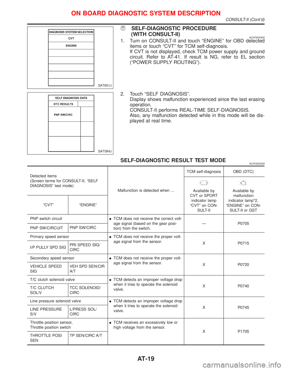
NCAT0022S021. Turn on CONSULT-II and touch ªENGINEº for OBD detected
items or touch ªCVTº for TCM self-diagnosis.
If CVT is not displayed, check TCM power supply and ground
circuit. Refer to AT-41. If result is NG, refer to EL section
(ªPOWER SUPPLY ROUTINGº).
2. Touch ªSELF DIAGNOSISº.
Display shows malfunction experienced since the last erasing
operation.
CONSULT-II performs REAL-TIME SELF-DIAGNOSIS.
Also, any malfunction detected while in this mode will be dis-
played at real time.
SELF-DIAGNOSTIC RESULT TEST MODENCAT0022S03
Detected items
(Screen terms for CONSULT-II, ªSELF
DIAGNOSISº test mode)
Malfunction is detected when ...TCM self-diagnosis OBD (DTC)
Available by
CVT or SPORT
indicator lamp
ªCVTº on CON-
SULT-IIAvailable by
malfunction
indicator lamp*2,
ªENGINEº on CON-
SULT-II or GST ªCVTº ªENGINEº
PNP switch circuitITCM does not receive the correct volt-
age signal (based on the gear posi-
tion) from the switch.Ð P0705
PNP SW/CIRCUITPNP SW/CIRC
Primary speed sensorITCM does not receive the proper volt-
age signal from the sensor.
X P0715
I/P PULLY SPD SIGPRI SPEED SIG/
CIRC
Secondary speed sensorITCM does not receive the proper volt-
age signal from the sensor.
X P0720
VEHICLE SPEED
SIGVEH SPD SEN/CIR
A/T
T/C clutch solenoid valveITCM detects an improper voltage drop
when it tries to operate the solenoid
valve.X P0740
T/C CLUTCH
SOL/VTCC SOLENOID/
CIRC
Line pressure solenoid valveITCM detects an improper voltage drop
when it tries to operate the solenoid
valve.X P0745
LINE PRESSURE
S/VL/PRESS SOL/
CIRC
Throttle position sensor,
Throttle position switchITCM receives an excessively low or
high voltage from the sensor.
X P1705
THROTTLE POSI
SENTP SEN/CIRC A/T
SAT651J
SAT584J
ON BOARD DIAGNOSTIC SYSTEM DESCRIPTION
CONSULT-II (Cont'd)
AT-19
Page 27 of 2267
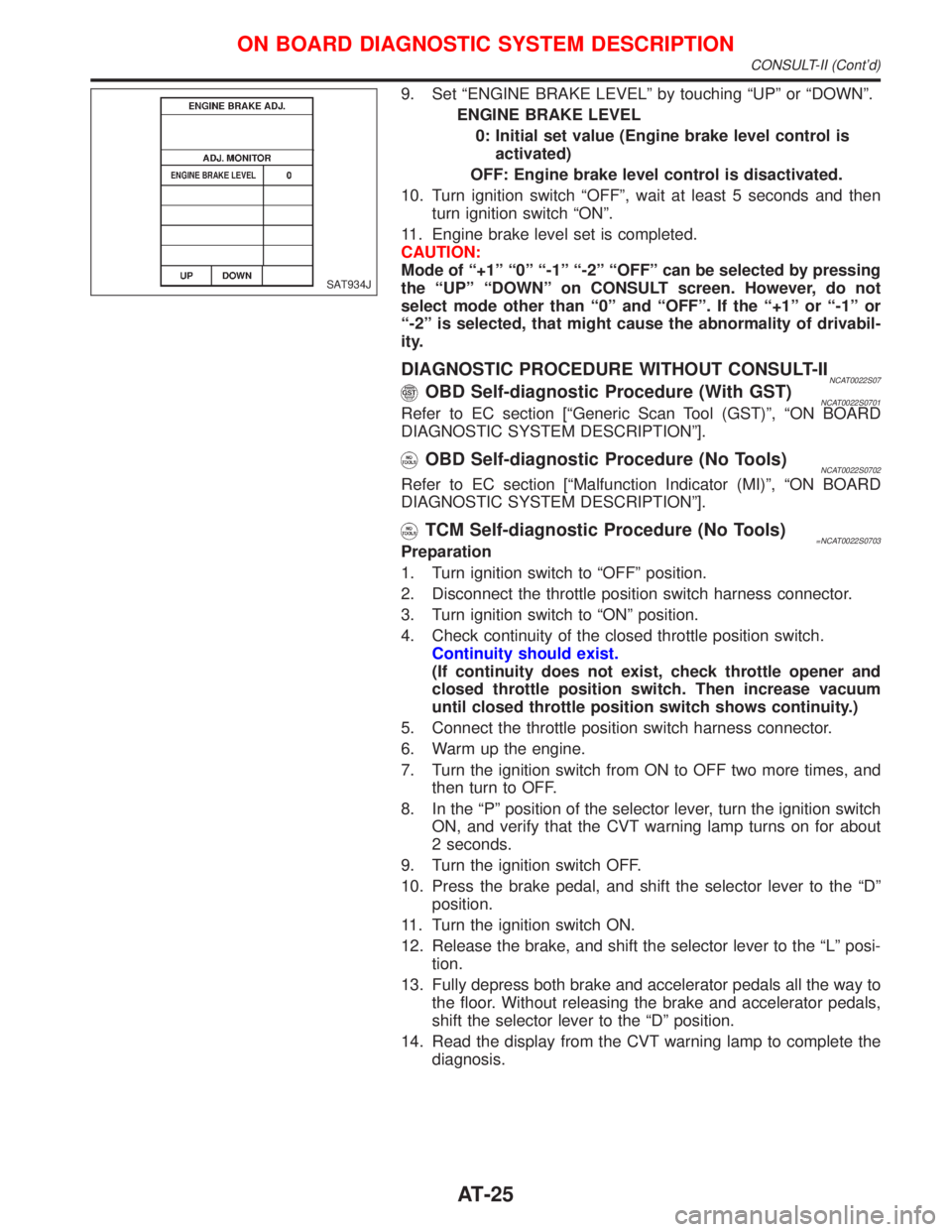
9. Set ªENGINE BRAKE LEVELº by touching ªUPº or ªDOWNº.
ENGINE BRAKE LEVEL
0: Initial set value (Engine brake level control is
activated)
OFF: Engine brake level control is disactivated.
10. Turn ignition switch ªOFFº, wait at least 5 seconds and then
turn ignition switch ªONº.
11. Engine brake level set is completed.
CAUTION:
Mode of ª+1º ª0º ª-1º ª-2º ªOFFº can be selected by pressing
the ªUPº ªDOWNº on CONSULT screen. However, do not
select mode other than ª0º and ªOFFº. If the ª+1º or ª-1º or
ª-2º is selected, that might cause the abnormality of drivabil-
ity.
DIAGNOSTIC PROCEDURE WITHOUT CONSULT-IINCAT0022S07OBD Self-diagnostic Procedure (With GST)NCAT0022S0701Refer to EC section [ªGeneric Scan Tool (GST)º, ªON BOARD
DIAGNOSTIC SYSTEM DESCRIPTIONº].
OBD Self-diagnostic Procedure (No Tools)NCAT0022S0702
Refer to EC section [ªMalfunction Indicator (MI)º, ªON BOARD
DIAGNOSTIC SYSTEM DESCRIPTIONº].
TCM Self-diagnostic Procedure (No Tools)=NCAT0022S0703Preparation
1. Turn ignition switch to ªOFFº position.
2. Disconnect the throttle position switch harness connector.
3. Turn ignition switch to ªONº position.
4. Check continuity of the closed throttle position switch.
Continuity should exist.
(If continuity does not exist, check throttle opener and
closed throttle position switch. Then increase vacuum
until closed throttle position switch shows continuity.)
5. Connect the throttle position switch harness connector.
6. Warm up the engine.
7. Turn the ignition switch from ON to OFF two more times, and
then turn to OFF.
8. In the ªPº position of the selector lever, turn the ignition switch
ON, and verify that the CVT warning lamp turns on for about
2 seconds.
9. Turn the ignition switch OFF.
10. Press the brake pedal, and shift the selector lever to the ªDº
position.
11. Turn the ignition switch ON.
12. Release the brake, and shift the selector lever to the ªLº posi-
tion.
13. Fully depress both brake and accelerator pedals all the way to
the floor. Without releasing the brake and accelerator pedals,
shift the selector lever to the ªDº position.
14. Read the display from the CVT warning lamp to complete the
diagnosis.
SAT934J
ON BOARD DIAGNOSTIC SYSTEM DESCRIPTION
CONSULT-II (Cont'd)
AT-25
Page 31 of 2267
IntroductionNCAT0023
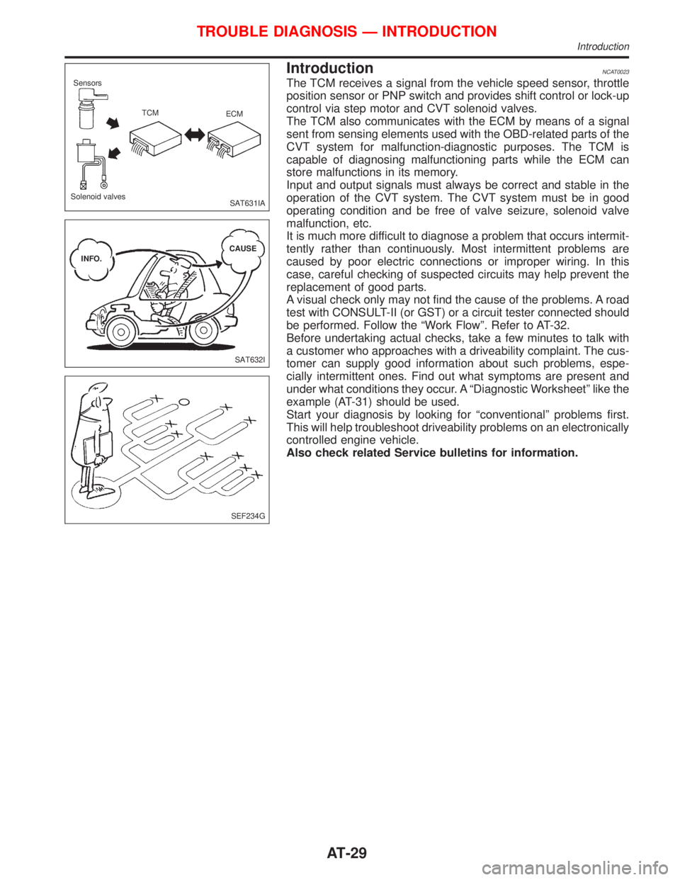
The TCM receives a signal from the vehicle speed sensor, throttle
position sensor or PNP switch and provides shift control or lock-up
control via step motor and CVT solenoid valves.
The TCM also communicates with the ECM by means of a signal
sent from sensing elements used with the OBD-related parts of the
CVT system for malfunction-diagnostic purposes. The TCM is
capable of diagnosing malfunctioning parts while the ECM can
store malfunctions in its memory.
Input and output signals must always be correct and stable in the
operation of the CVT system. The CVT system must be in good
operating condition and be free of valve seizure, solenoid valve
malfunction, etc.
It is much more difficult to diagnose a problem that occurs intermit-
tently rather than continuously. Most intermittent problems are
caused by poor electric connections or improper wiring. In this
case, careful checking of suspected circuits may help prevent the
replacement of good parts.
A visual check only may not find the cause of the problems. A road
test with CONSULT-II (or GST) or a circuit tester connected should
be performed. Follow the ªWork Flowº. Refer to AT-32.
Before undertaking actual checks, take a few minutes to talk with
a customer who approaches with a driveability complaint. The cus-
tomer can supply good information about such problems, espe-
cially intermittent ones. Find out what symptoms are present and
under what conditions they occur. A ªDiagnostic Worksheetº like the
example (AT-31) should be used.
Start your diagnosis by looking for ªconventionalº problems first.
This will help troubleshoot driveability problems on an electronically
controlled engine vehicle.
Also check related Service bulletins for information.
SAT631IA Sensors
TCM
ECM
Solenoid valves
SAT632I INFO.CAUSE
SEF234G
TROUBLE DIAGNOSIS Ð INTRODUCTION
Introduction
AT-29
Page 33 of 2267
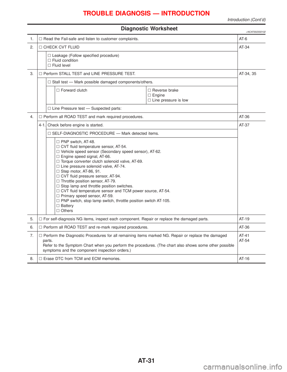
Diagnostic Worksheet=NCAT0023S0102
1.lRead the Fail-safe and listen to customer complaints. AT-6
2.lCHECK CVT FLUIDAT-34
lLeakage (Follow specified procedure)
lFluid condition
lFluid level
3.lPerform STALL TEST and LINE PRESSURE TEST. AT-34, 35
lStall test Ð Mark possible damaged components/others.
lForward clutchlReverse brake
lEngine
lLine pressure is low
lLine Pressure test Ð Suspected parts:
4.lPerform all ROAD TEST and mark required procedures. AT-36
4-1. Check before engine is started.AT-37
lSELF-DIAGNOSTIC PROCEDURE Ð Mark detected items.
lPNP switch, AT-48.
lCVT fluid temperature sensor, AT-54.
lVehicle speed sensor (Secondary speed sensor), AT-62.
lEngine speed signal, AT-66.
lTorque converter clutch solenoid valve, AT-69.
lLine pressure solenoid valve, AT-74.
lStep motor, AT-86, 91.
lCVT fluid pressure sensor, AT-94.
lThrottle position sensor, AT-79.
lStop lamp and throttle position switches.
lCVT fluid temperature sensor and TCM power source, AT-54.
lPrimary speed sensor, AT-59.
lPNP switch, stop lamp switch, throttle position switch AT-105.
lBattery
lOthers
5.lFor self-diagnosis NG items, inspect each component. Repair or replace the damaged parts. AT-19
6.lPerform all ROAD TEST and re-mark required procedures. AT-36
7.lPerform the Diagnostic Procedures for all remaining items marked NG. Repair or replace the damaged
parts.
Refer to the Symptom Chart when you perform the procedures. (The chart also shows some other possible
symptoms and the component inspection orders.)AT-41
AT-54
8.lErase DTC from TCM and ECM memories. AT-16
TROUBLE DIAGNOSIS Ð INTRODUCTION
Introduction (Cont'd)
AT-31
Page 36 of 2267
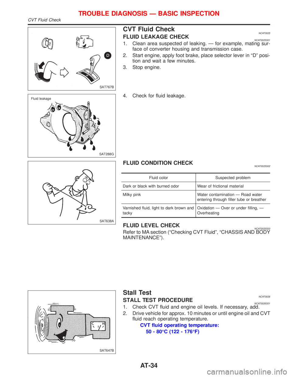
CVT Fluid CheckNCAT0025FLUID LEAKAGE CHECKNCAT0025S011. Clean area suspected of leaking. Ð for example, mating sur-
face of converter housing and transmission case.
2. Start engine, apply foot brake, place selector lever in ªDº posi-
tion and wait a few minutes.
3. Stop engine.
4. Check for fluid leakage.
FLUID CONDITION CHECKNCAT0025S02
Fluid color Suspected problem
Dark or black with burned odor Wear of frictional material
Milky pink Water contamination Ð Road water
entering through filler tube or breather
Varnished fluid, light to dark brown and
tackyOxidation Ð Over or under filling, Ð
Overheating
FLUID LEVEL CHECKNCAT0025S03Refer to MA section (ªChecking CVT Fluidº, ªCHASSIS AND BODY
MAINTENANCEº).
Stall TestNCAT0026STALL TEST PROCEDURENCAT0026S011. Check CVT fluid and engine oil levels. If necessary, add.
2. Drive vehicle for approx. 10 minutes or until engine oil and CVT
fluid reach operating temperature.
CVT fluid operating temperature:
50 - 80ÉC (122 - 176ÉF)
SAT767B
SAT288G Fluid leakage
SAT638A
SAT647B
TROUBLE DIAGNOSIS Ð BASIC INSPECTION
CVT Fluid Check
AT-34
Page 37 of 2267
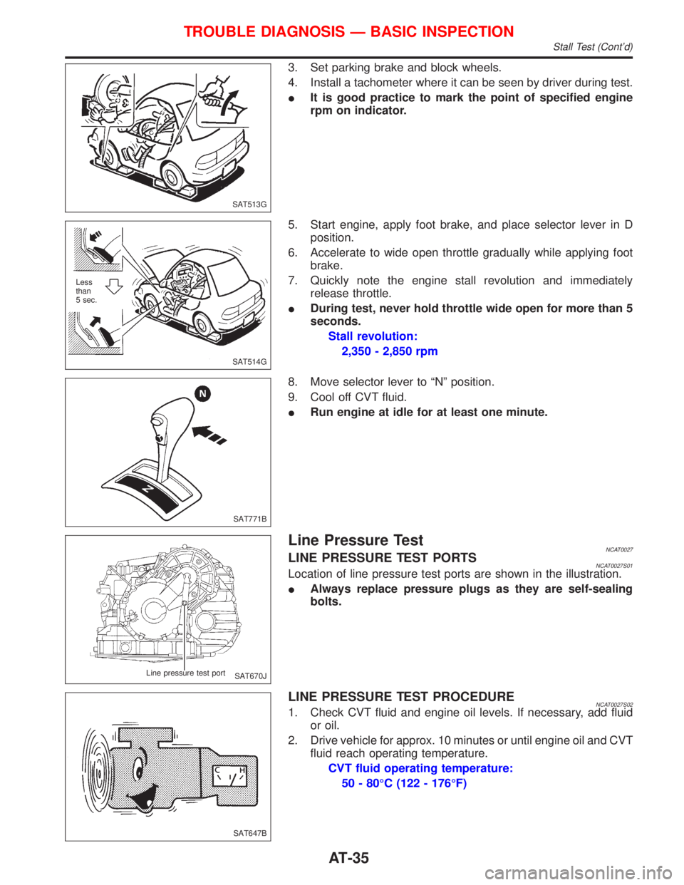
3. Set parking brake and block wheels.
4. Install a tachometer where it can be seen by driver during test.
IIt is good practice to mark the point of specified engine
rpm on indicator.
5. Start engine, apply foot brake, and place selector lever in D
position.
6. Accelerate to wide open throttle gradually while applying foot
brake.
7. Quickly note the engine stall revolution and immediately
release throttle.
IDuring test, never hold throttle wide open for more than 5
seconds.
Stall revolution:
2,350 - 2,850 rpm
8. Move selector lever to ªNº position.
9. Cool off CVT fluid.
IRun engine at idle for at least one minute.
Line Pressure TestNCAT0027LINE PRESSURE TEST PORTSNCAT0027S01Location of line pressure test ports are shown in the illustration.
IAlways replace pressure plugs as they are self-sealing
bolts.
LINE PRESSURE TEST PROCEDURENCAT0027S021. Check CVT fluid and engine oil levels. If necessary, add fluid
or oil.
2. Drive vehicle for approx. 10 minutes or until engine oil and CVT
fluid reach operating temperature.
CVT fluid operating temperature:
50 - 80ÉC (122 - 176ÉF)
SAT513G
SAT514G Less
than
5 sec.
SAT771B
SAT670J Line pressure test port
SAT647B
TROUBLE DIAGNOSIS Ð BASIC INSPECTION
Stall Test (Cont'd)
AT-35