1999 NISSAN PRIMERA air bleeding
[x] Cancel search: air bleedingPage 123 of 2267
BRAKE SYSTEM
SECTION
BR
CONTENTS
PRECAUTIONS............................................................. 3
Supplemental Restraint System (SRS)²AIR
BAG²and²SEAT BELT PRE-TENSIONER²............. 3
Precautions for Brake System ................................... 3
Precautions When Working On ABS ......................... 4
Wiring Diagrams and Trouble Diagnosis ................... 4
PRECAUTIONS AND PREPARATION.......................... 5
Commercial Service Tools ......................................... 5
NOISE, VIBRATION AND HARSHNESS (NVH)
TROUBLE SHOOTING.................................................. 6
NVH Troubleshooting Chart....................................... 6
CHECK AND ADJUSTMENT........................................ 7
Checking Brake Fluid Level....................................... 7
Checking Brake Line ................................................. 7
Changing Brake Fluid ................................................ 7
Brake Burnishing Procedure...................................... 7
Bleeding Brake System ............................................. 8
BRAKE HYDRAULIC LINE........................................... 9
Removal ................................................................... 10
Inspection................................................................. 10
Installation ................................................................ 10
CONTROL VALVE........................................................ 11
Dual Proportioning Valve .......................................... 11
BRAKE PEDAL AND BRACKET................................ 13
Removal and Installation ......................................... 13
Inspection................................................................. 13
Adjustment ............................................................... 13
MASTER CYLINDER................................................... 15
Removal ................................................................... 15
Disassembly............................................................. 15
Inspection................................................................. 16
Assembly ................................................................. 16
Installation ................................................................ 17BRAKE BOOSTER...................................................... 18
On-vehicle Service................................................... 18
Removal ................................................................... 18
Inspection................................................................. 19
Installation ................................................................ 19
VACUUM HOSE........................................................... 20
Removal and Installation ......................................... 21
Inspection................................................................. 21
FRONT DISC BRAKE................................................. 23
Pad Replacement .................................................... 23
Removal ................................................................... 24
Disassembly............................................................. 25
Inspection - Caliper.................................................. 25
SR20DE - M/T
FRONT DISC BRAKE................................................. 26
Pad Replacement .................................................... 26
Installation ................................................................ 28
Removal ................................................................... 29
Disassembly............................................................. 29
Inspection - Caliper.................................................. 29
FRONT DISC BRAKE................................................. 31
Inspection - Rotor .................................................... 31
Assembly ................................................................. 31
Installation ................................................................ 32
REAR DISC BRAKE TYPE 1...................................... 33
Component .............................................................. 33
Pad Replacement .................................................... 33
Removal ................................................................... 35
Disassembly............................................................. 35
BR
Page 129 of 2267
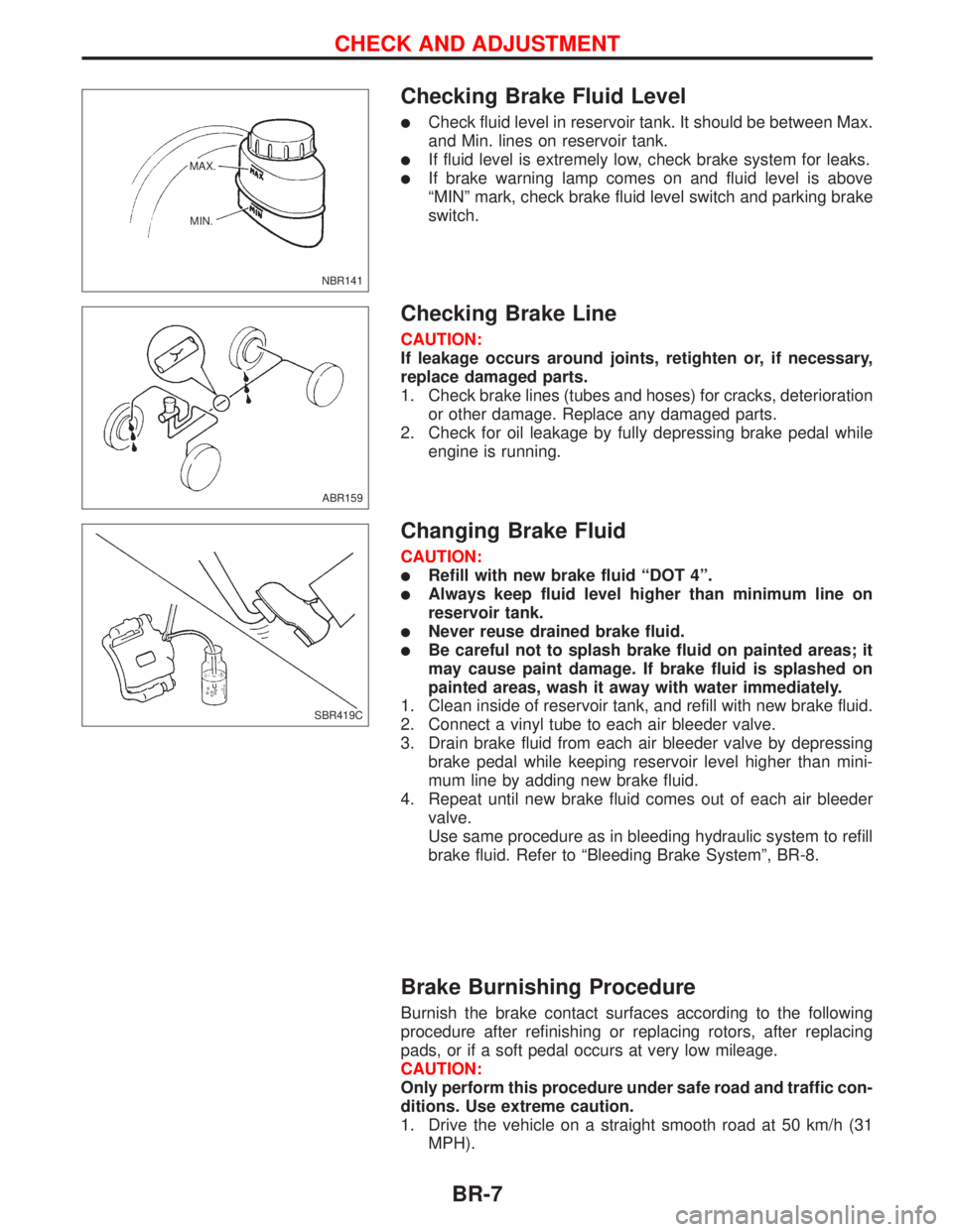
Checking Brake Fluid Level
lCheck fluid level in reservoir tank. It should be between Max.
and Min. lines on reservoir tank.
lIf fluid level is extremely low, check brake system for leaks.
lIf brake warning lamp comes on and fluid level is above
ªMINº mark, check brake fluid level switch and parking brake
switch.
Checking Brake Line
CAUTION:
If leakage occurs around joints, retighten or, if necessary,
replace damaged parts.
1. Check brake lines (tubes and hoses) for cracks, deterioration
or other damage. Replace any damaged parts.
2. Check for oil leakage by fully depressing brake pedal while
engine is running.
Changing Brake Fluid
CAUTION:
lRefill with new brake fluid ªDOT 4º.
lAlways keep fluid level higher than minimum line on
reservoir tank.
lNever reuse drained brake fluid.
lBe careful not to splash brake fluid on painted areas; it
may cause paint damage. If brake fluid is splashed on
painted areas, wash it away with water immediately.
1. Clean inside of reservoir tank, and refill with new brake fluid.
2. Connect a vinyl tube to each air bleeder valve.
3. Drain brake fluid from each air bleeder valve by depressing
brake pedal while keeping reservoir level higher than mini-
mum line by adding new brake fluid.
4. Repeat until new brake fluid comes out of each air bleeder
valve.
Use same procedure as in bleeding hydraulic system to refill
brake fluid. Refer to ªBleeding Brake Systemº, BR-8.
Brake Burnishing Procedure
Burnish the brake contact surfaces according to the following
procedure after refinishing or replacing rotors, after replacing
pads, or if a soft pedal occurs at very low mileage.
CAUTION:
Only perform this procedure under safe road and traffic con-
ditions. Use extreme caution.
1. Drive the vehicle on a straight smooth road at 50 km/h (31
MPH).
NBR141 MAX.
MIN.
ABR159
SBR419C
CHECK AND ADJUSTMENT
BR-7
Page 130 of 2267
2. Use medium brake pedal/foot effort to bring the vehicle to a
complete stop from 50 km/h (31 MPH). Adjust brake pedal/
foot pressure such that vehicle stopping time equals 3 to 5
seconds.
3. To cool the brake system, drive the vehicle at 50 km/h (31
MPH) for 1 minute without stopping.
4. Repeat steps 1 to 3, 10 times or more to complete the bur-
nishing procedure.
Bleeding Brake System
CAUTION:
lCarefully monitor brake fluid level at master cylinder
during bleeding operation.
lIf master cylinder is suspected to have air inside, bleed
air from master cylinder first. Refer to ªInstallationº,
ªMASTER CYLINDERº, BR-17.
lFill reservoir with new brake fluid ªDOT 4º. Make sure it
is full at all times while bleeding air out of system.
lPlace a container under master cylinder to avoid spillage
of brake fluid.
lFor models with ABS, turn ignition switch to the OFF
position and disconnect ABS fuse or battery cable.
lBleed air in the following order:
RHD models
Left rear brake,Right front brake,Right rear brake,Left
front brake
LHD models
Right rear brake,Left front brake,Left rear brake,Right
front brake.
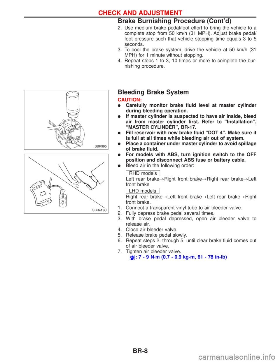
1. Connect a transparent vinyl tube to air bleeder valve.
2. Fully depress brake pedal several times.
3. With brake pedal depressed, open air bleeder valve to
release air.
4. Close air bleeder valve.
5. Release brake pedal slowly.
6. Repeat steps 2. through 5. until clear brake fluid comes out
of air bleeder valve.
7. Tighten air bleeder valve.
:7-9N´m(0.7 - 0.9 kg-m, 61 - 78 in-lb)
SBR995
SBR419C
CHECK AND ADJUSTMENT
Brake Burnishing Procedure (Cont'd)
BR-8
Page 132 of 2267
Removal
CAUTION:
lBe careful not to splash brake fluid on painted areas; it
may cause paint damage. If brake fluid is splashed on
painted areas, wash it away with water immediately.
lAll hoses and tubes must be free from excessive
bending, twisting and pulling.
lFor rear disc caliper, care should be taken as not to let
air enter the body.
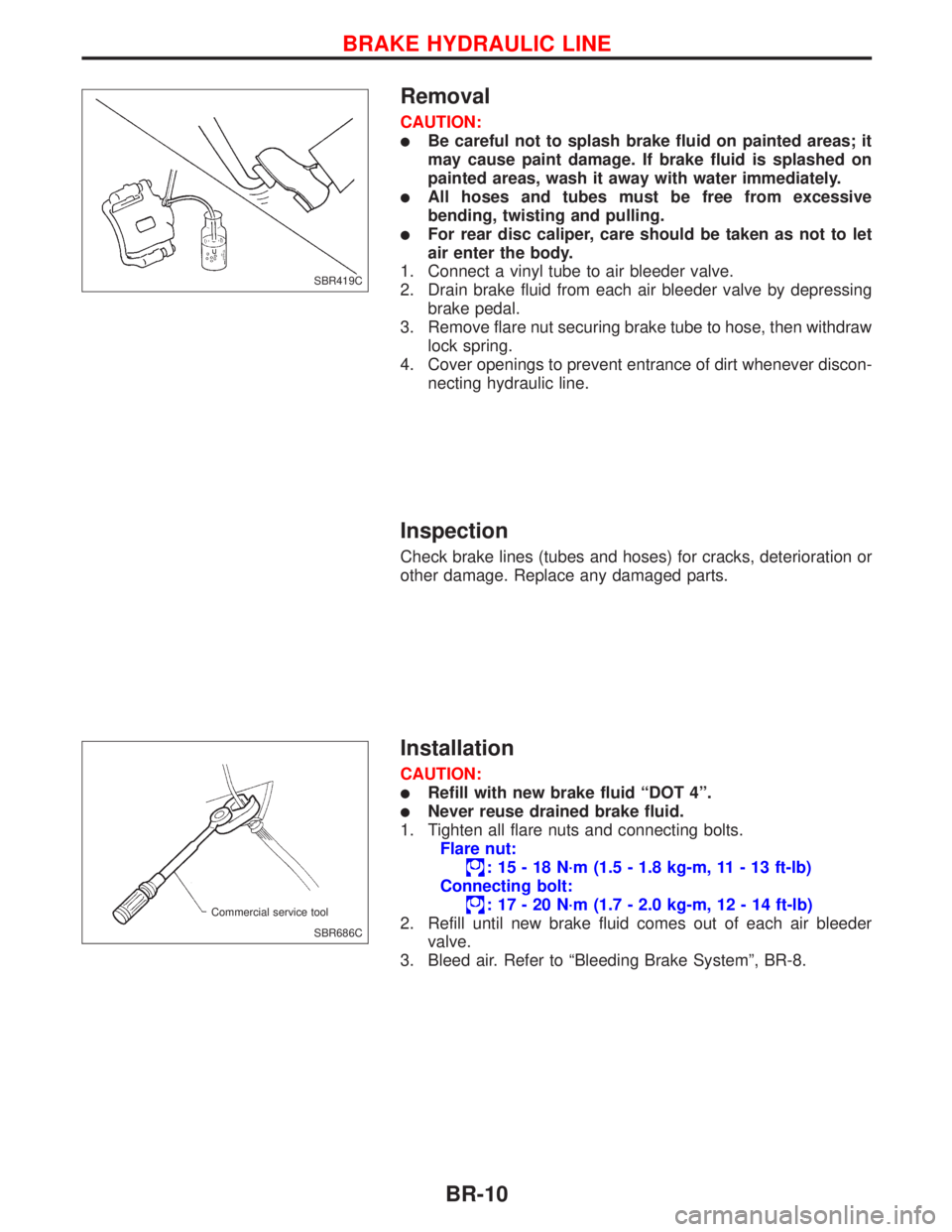
1. Connect a vinyl tube to air bleeder valve.
2. Drain brake fluid from each air bleeder valve by depressing
brake pedal.
3. Remove flare nut securing brake tube to hose, then withdraw
lock spring.
4. Cover openings to prevent entrance of dirt whenever discon-
necting hydraulic line.
Inspection
Check brake lines (tubes and hoses) for cracks, deterioration or
other damage. Replace any damaged parts.
Installation
CAUTION:
lRefill with new brake fluid ªDOT 4º.
lNever reuse drained brake fluid.
1. Tighten all flare nuts and connecting bolts.
Flare nut:
: 15 - 18 N´m (1.5 - 1.8 kg-m, 11 - 13 ft-lb)
Connecting bolt:
: 17 - 20 N´m (1.7 - 2.0 kg-m, 12 - 14 ft-lb)
2. Refill until new brake fluid comes out of each air bleeder
valve.
3. Bleed air. Refer to ªBleeding Brake Systemº, BR-8.
SBR419C
SBR686C Commercial service tool
BRAKE HYDRAULIC LINE
BR-10
Page 133 of 2267
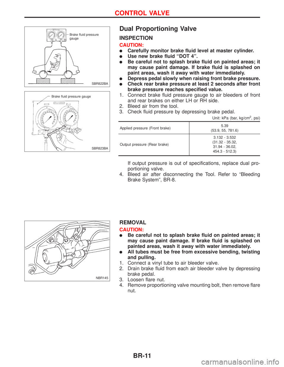
Dual Proportioning Valve
INSPECTION
CAUTION:
lCarefully monitor brake fluid level at master cylinder.
lUse new brake fluid ªDOT 4º.
lBe careful not to splash brake fluid on painted areas; it
may cause paint damage. If brake fluid is splashed on
paint areas, wash it away with water immediately.
lDepress pedal slowly when raising front brake pressure.
lCheck rear brake pressure at least 2 seconds after front
brake pressure reaches specified value.
1. Connect brake fluid pressure gauge to air bleeders of front
and rear brakes on either LH or RH side.
2. Bleed air from the tool.
3. Check fluid pressure by depressing brake pedal.
Unit: kPa (bar, kg/cm2, psi)
Applied pressure (Front brake)5.39
(53.9, 55, 781.6)
Output pressure (Rear brake)3.132 - 3.532
(31.32 - 35.32,
31.94 - 36.02,
454.3 - 512.3)
If output pressure is out of specifications, replace dual pro-
portioning valve.
4. Bleed air after disconnecting the Tool. Refer to ªBleeding
Brake Systemº, BR-8.
REMOVAL
CAUTION:
lBe careful not to splash brake fluid on painted areas; it
may cause paint damage. If brake fluid is splashed on
painted areas, wash it away with water immediately.
lAll tubes must be free from excessive bending, twisting
and pulling.
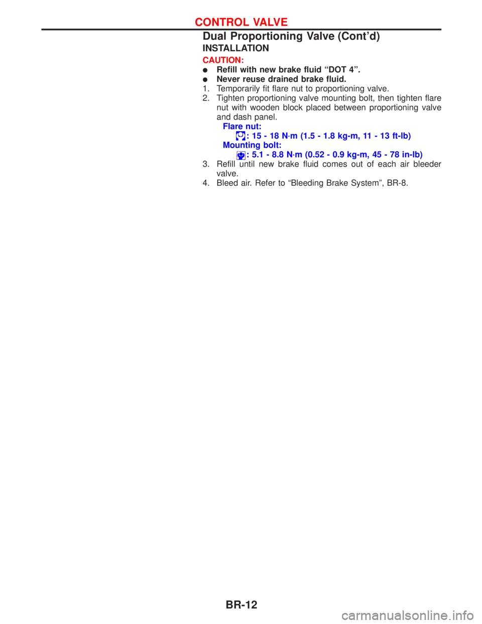
1. Connect a vinyl tube to air bleeder valve.
2. Drain brake fluid from each air bleeder valve by depressing
brake pedal.
3. Loosen flare nut.
4. Remove proportioning valve mounting bolt, then remove flare
nut.
SBR822BA Brake fluid pressure
gauge
SBR823BA Brake fluid pressure gauge
NBR145
CONTROL VALVE
BR-11
Page 134 of 2267
INSTALLATION
CAUTION:
lRefill with new brake fluid ªDOT 4º.
lNever reuse drained brake fluid.
1. Temporarily fit flare nut to proportioning valve.
2. Tighten proportioning valve mounting bolt, then tighten flare
nut with wooden block placed between proportioning valve
and dash panel.
Flare nut:
: 15 - 18 N´m (1.5 - 1.8 kg-m, 11 - 13 ft-lb)
Mounting bolt:
: 5.1 - 8.8 N´m (0.52 - 0.9 kg-m, 45 - 78 in-lb)
3. Refill until new brake fluid comes out of each air bleeder
valve.
4. Bleed air. Refer to ªBleeding Brake Systemº, BR-8.
CONTROL VALVE
Dual Proportioning Valve (Cont'd)
BR-12
Page 139 of 2267
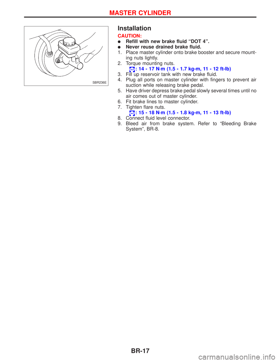
Installation
CAUTION:
lRefill with new brake fluid ªDOT 4º.
lNever reuse drained brake fluid.
1. Place master cylinder onto brake booster and secure mount-
ing nuts lightly.
2. Torque mounting nuts.
: 14 - 17 N´m (1.5 - 1.7 kg-m, 11 - 12 ft-lb)
3. Fill up reservoir tank with new brake fluid.
4. Plug all ports on master cylinder with fingers to prevent air
suction while releasing brake pedal.
5. Have driver depress brake pedal slowly several times until no
air comes out of master cylinder.
6. Fit brake lines to master cylinder.
7. Tighten flare nuts.
: 15 - 18 N´m (1.5 - 1.8 kg-m, 11 - 13 ft-lb)
8. Connect fluid level connector.
9. Bleed air from brake system. Refer to ªBleeding Brake
Systemº, BR-8.
SBR236E
MASTER CYLINDER
BR-17
Page 141 of 2267
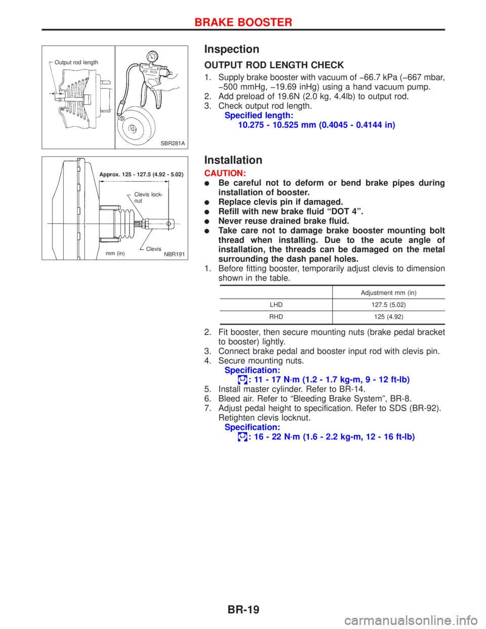
Inspection
OUTPUT ROD LENGTH CHECK
1. Supply brake booster with vacuum of þ66.7 kPa (þ667 mbar,
þ500 mmHg, þ19.69 inHg) using a hand vacuum pump.
2. Add preload of 19.6N (2.0 kg, 4.4lb) to output rod.
3. Check output rod length.
Specified length:
10.275 - 10.525 mm (0.4045 - 0.4144 in)
Installation
CAUTION:
lBe careful not to deform or bend brake pipes during
installation of booster.
lReplace clevis pin if damaged.
lRefill with new brake fluid ªDOT 4º.
lNever reuse drained brake fluid.
lTake care not to damage brake booster mounting bolt
thread when installing. Due to the acute angle of
installation, the threads can be damaged on the metal
surrounding the dash panel holes.
1. Before fitting booster, temporarily adjust clevis to dimension
shown in the table.
Adjustment mm (in)
LHD 127.5 (5.02)
RHD 125 (4.92)
2. Fit booster, then secure mounting nuts (brake pedal bracket
to booster) lightly.
3. Connect brake pedal and booster input rod with clevis pin.
4. Secure mounting nuts.
Specification:
: 11 - 17 N´m (1.2 - 1.7 kg-m,9-12ft-lb)
5. Install master cylinder. Refer to BR-14.
6. Bleed air. Refer to ªBleeding Brake Systemº, BR-8.
7. Adjust pedal height to specification. Refer to SDS (BR-92).
Retighten clevis locknut.
Specification:
: 16 - 22 N´m (1.6 - 2.2 kg-m, 12 - 16 ft-lb)
SBR281A Output rod length
Approx. 125 - 127.5 (4.92 - 5.02)
Clevis Clevis lock-
nut
mm (in)
NBR191
BRAKE BOOSTER
BR-19