Page 154 of 2267
Installation
CAUTION:
lRefill with new brake fluid ªDOT 4º.
lNever reuse drained brake fluid.
1. Install brake hose to caliper securely.
2. Install all parts and secure all bolts.
3. Bleed air. Refer to ªBleeding Brake Systemº BR-8.
NBR160
.Protrusions
NBR298 Protrusions
FRONT DISC BRAKE
BR-32
Page 161 of 2267
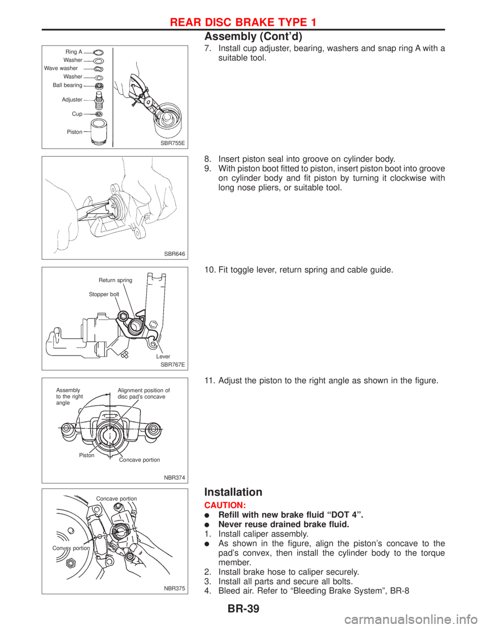
7. Install cup adjuster, bearing, washers and snap ring A with a
suitable tool.
8. Insert piston seal into groove on cylinder body.
9. With piston boot fitted to piston, insert piston boot into groove
on cylinder body and fit piston by turning it clockwise with
long nose pliers, or suitable tool.
10. Fit toggle lever, return spring and cable guide.
11. Adjust the piston to the right angle as shown in the figure.
Installation
CAUTION:
lRefill with new brake fluid ªDOT 4º.
lNever reuse drained brake fluid.
1. Install caliper assembly.
lAs shown in the figure, align the piston's concave to the
pad's convex, then install the cylinder body to the torque
member.
2. Install brake hose to caliper securely.
3. Install all parts and secure all bolts.
4. Bleed air. Refer to ªBleeding Brake Systemº, BR-8
SBR755E Ring A
Washer
Wave washer
Washer
Ball bearing
Adjuster
Cup
Piston
SBR646
SBR767E Stopper boltReturn spring
Lever
NBR374 Alignment position of
disc pad's concave
Concave portion Piston Assembly
to the right
angle
NBR375 Concave portion
Convex portion
REAR DISC BRAKE TYPE 1
Assembly (Cont'd)
BR-39
Page 165 of 2267
ROTOR
Rubbing Surface
Check rotor for roughness, cracks or chips.
Runout
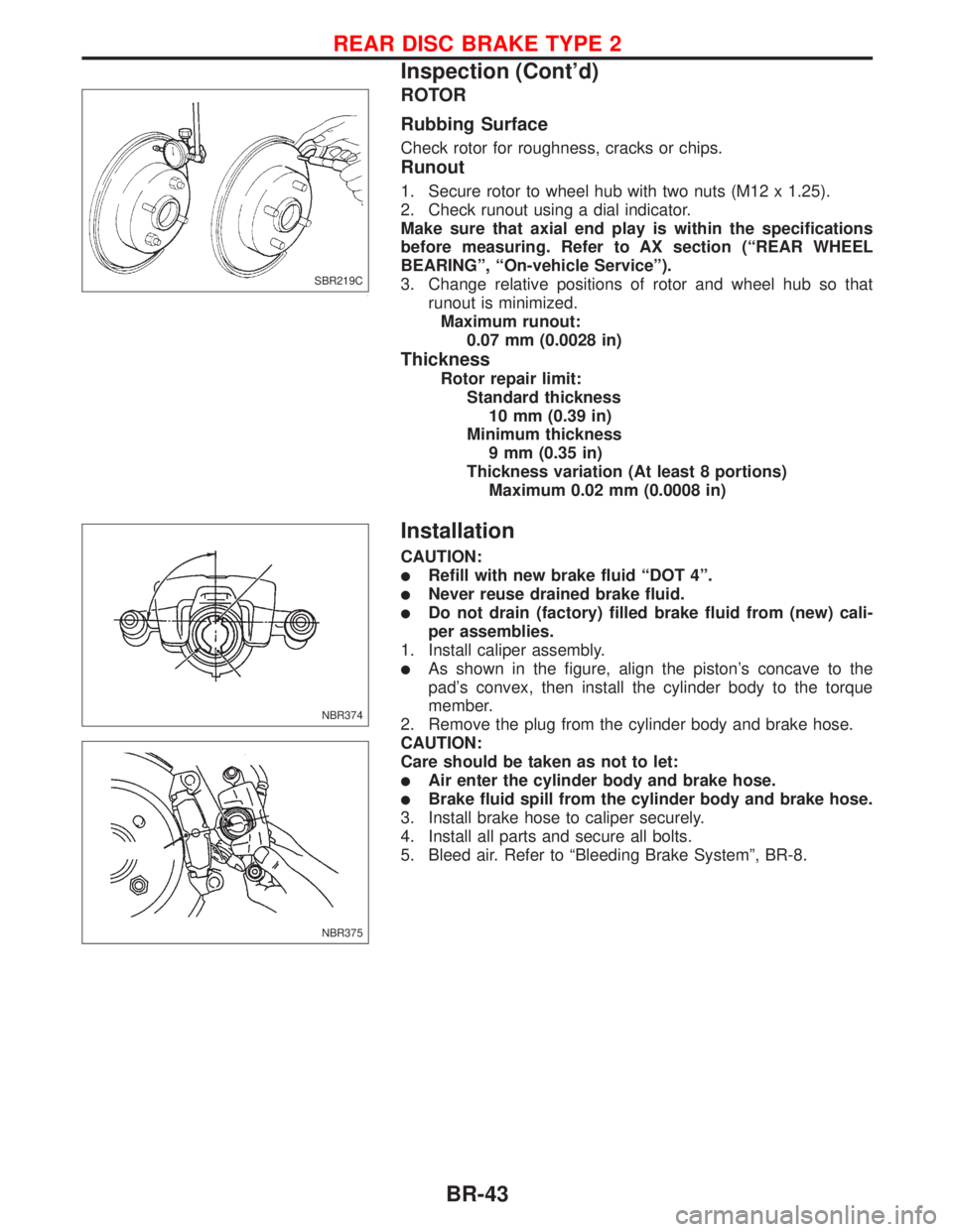
1. Secure rotor to wheel hub with two nuts (M12 x 1.25).
2. Check runout using a dial indicator.
Make sure that axial end play is within the specifications
before measuring. Refer to AX section (ªREAR WHEEL
BEARINGº, ªOn-vehicle Serviceº).
3. Change relative positions of rotor and wheel hub so that
runout is minimized.
Maximum runout:
0.07 mm (0.0028 in)
Thickness
Rotor repair limit:
Standard thickness
10 mm (0.39 in)
Minimum thickness
9 mm (0.35 in)
Thickness variation (At least 8 portions)
Maximum 0.02 mm (0.0008 in)
Installation
CAUTION:
lRefill with new brake fluid ªDOT 4º.
lNever reuse drained brake fluid.
lDo not drain (factory) filled brake fluid from (new) cali-
per assemblies.
1. Install caliper assembly.
lAs shown in the figure, align the piston's concave to the
pad's convex, then install the cylinder body to the torque
member.
2. Remove the plug from the cylinder body and brake hose.
CAUTION:
Care should be taken as not to let:
lAir enter the cylinder body and brake hose.
lBrake fluid spill from the cylinder body and brake hose.
3. Install brake hose to caliper securely.
4. Install all parts and secure all bolts.
5. Bleed air. Refer to ªBleeding Brake Systemº, BR-8.
SBR219C
NBR374
NBR375
REAR DISC BRAKE TYPE 2
Inspection (Cont'd)
BR-43
Page 169 of 2267
3. Shorten adjuster by rotating it.
lTo tighten loosened brake shoes, first, insert a screw driver
in the direction shown in the left. Then, move the adjuster in
the direction shown by the arrow while disengaging the tooth
contact. Never tap the area E.
4. Connect parking brake cable to toggle lever.
5. Install all parts.
Be careful not to damage wheel cylinder piston boots.
6. Check all parts are installed properly.
Pay attention to direction of adjuster assembly.
7. Install brake drum.
8. When installing new wheel cylinder or overhauling wheel
cylinder, bleed air. Refer to ªBleeding Brake Systemº, BR-8.
9. Adjust parking brake. Refer to BR-49.
SBR619E
REAR DRUM BRAKE
Installation (Cont'd)
BR-47
Page 178 of 2267
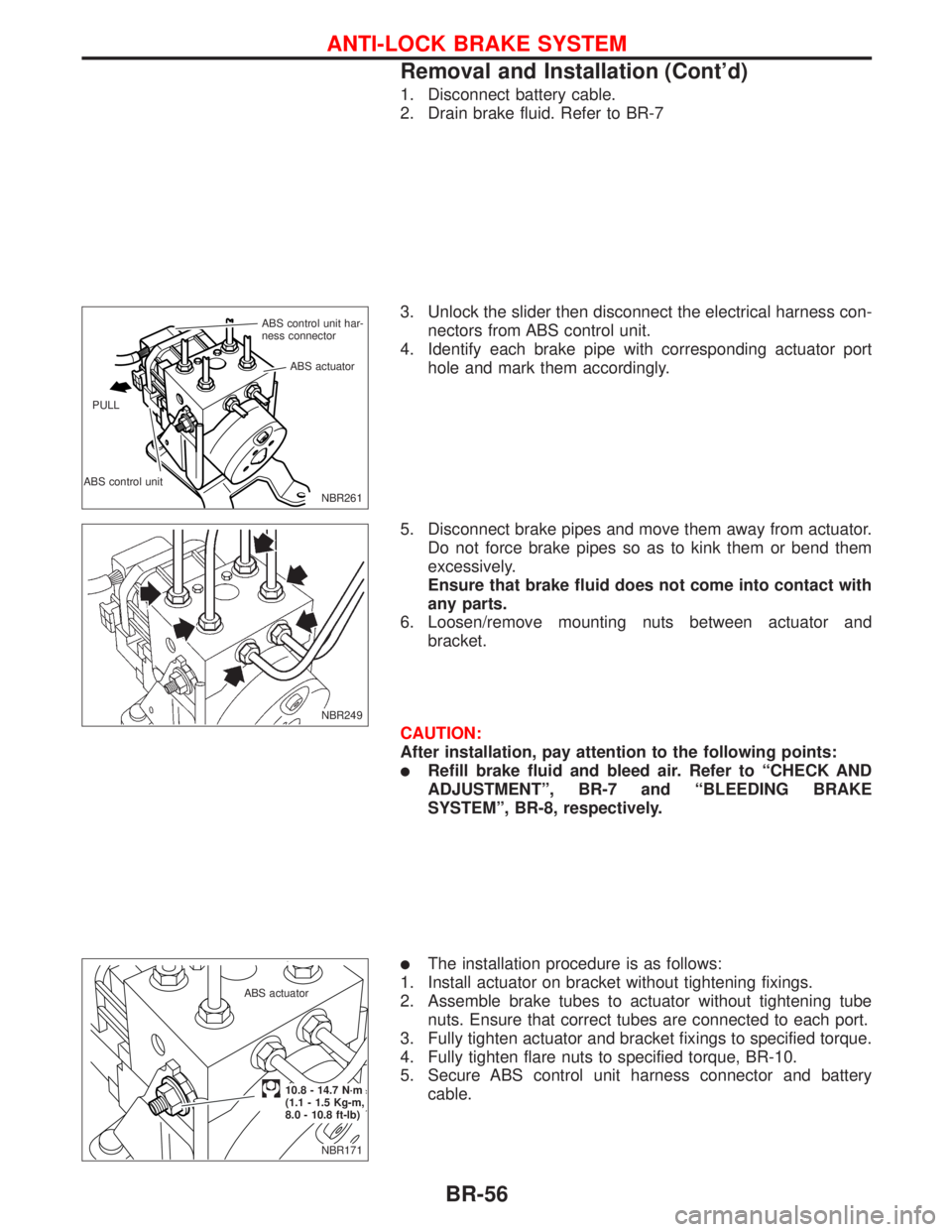
1. Disconnect battery cable.
2. Drain brake fluid. Refer to BR-7
3. Unlock the slider then disconnect the electrical harness con-
nectors from ABS control unit.
4. Identify each brake pipe with corresponding actuator port
hole and mark them accordingly.
5. Disconnect brake pipes and move them away from actuator.
Do not force brake pipes so as to kink them or bend them
excessively.
Ensure that brake fluid does not come into contact with
any parts.
6. Loosen/remove mounting nuts between actuator and
bracket.
CAUTION:
After installation, pay attention to the following points:
lRefill brake fluid and bleed air. Refer to ªCHECK AND
ADJUSTMENTº, BR-7 and ªBLEEDING BRAKE
SYSTEMº, BR-8, respectively.
lThe installation procedure is as follows:
1. Install actuator on bracket without tightening fixings.
2. Assemble brake tubes to actuator without tightening tube
nuts. Ensure that correct tubes are connected to each port.
3. Fully tighten actuator and bracket fixings to specified torque.
4. Fully tighten flare nuts to specified torque, BR-10.
5. Secure ABS control unit harness connector and battery
cable.
NBR261 ABS control unit har-
ness connector
ABS control unitABS actuator
PULL
NBR249
NBR171 ABS actuator
.10.8 - 14.7 N´m
(1.1 - 1.5 Kg-m,
8.0 - 10.8 ft-lb)
ANTI-LOCK BRAKE SYSTEM
Removal and Installation (Cont'd)
BR-56
Page 208 of 2267
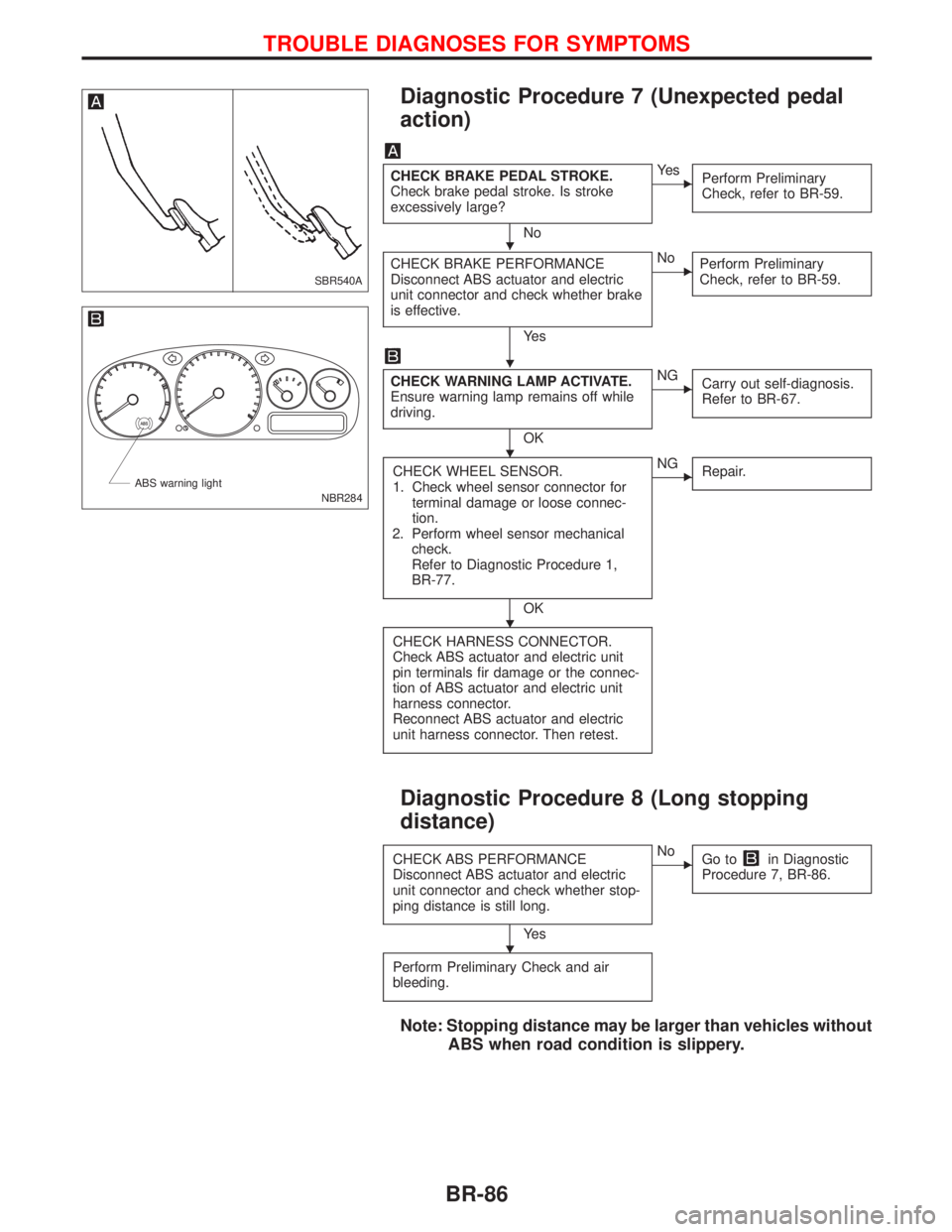
Diagnostic Procedure 7 (Unexpected pedal
action)
CHECK BRAKE PEDAL STROKE.
Check brake pedal stroke. Is stroke
excessively large?
No
EYe s
Perform Preliminary
Check, refer to BR-59.
CHECK BRAKE PERFORMANCE
Disconnect ABS actuator and electric
unit connector and check whether brake
is effective.
Ye s
ENo
Perform Preliminary
Check, refer to BR-59.
CHECK WARNING LAMP ACTIVATE.
Ensure warning lamp remains off while
driving.
OK
ENG
Carry out self-diagnosis.
Refer to BR-67.
CHECK WHEEL SENSOR.
1. Check wheel sensor connector for
terminal damage or loose connec-
tion.
2. Perform wheel sensor mechanical
check.
Refer to Diagnostic Procedure 1,
BR-77.
OK
ENG
Repair.
CHECK HARNESS CONNECTOR.
Check ABS actuator and electric unit
pin terminals fir damage or the connec-
tion of ABS actuator and electric unit
harness connector.
Reconnect ABS actuator and electric
unit harness connector. Then retest.
Diagnostic Procedure 8 (Long stopping
distance)
CHECK ABS PERFORMANCE
Disconnect ABS actuator and electric
unit connector and check whether stop-
ping distance is still long.
Ye s
ENo
Go toin Diagnostic
Procedure 7, BR-86.
Perform Preliminary Check and air
bleeding.
Note: Stopping distance may be larger than vehicles without
ABS when road condition is slippery.
SBR540A
NBR284 ABS warning light
H
H
H
H
H
TROUBLE DIAGNOSES FOR SYMPTOMS
BR-86
Page 285 of 2267
Bleeding Procedure
1. Bleed air from clutch operating cylinder according to the fol-
lowing procedure.
Carefully monitor fluid level at master cylinder during bleed-
ing operation.
a. Top up reservoir with recommended brake fluid.
b. Connect a transparent vinyl tube to air bleeder valve of clutch
operating cylinder.
c. Fully depress clutch pedal several times.
d. With clutch pedal depressed, open bleeder valve to release
air.
e. Close bleeder valve.
f. Repeat steps (c) through (e) above until brake fluid flows
from air bleeder valve without air bubbles.
2. Bleed air from clutch damper according to the above proce-
dure.
3. Repeat the above bleeding procedures 1 and 2 several
times.
.NCL005
.Operating cylinder
.Air bleeder valve
NCL006 Air bleed valve
.Clutch
damper
INSPECTION AND ADJUSTMENT
CL-7
Page 1638 of 2267
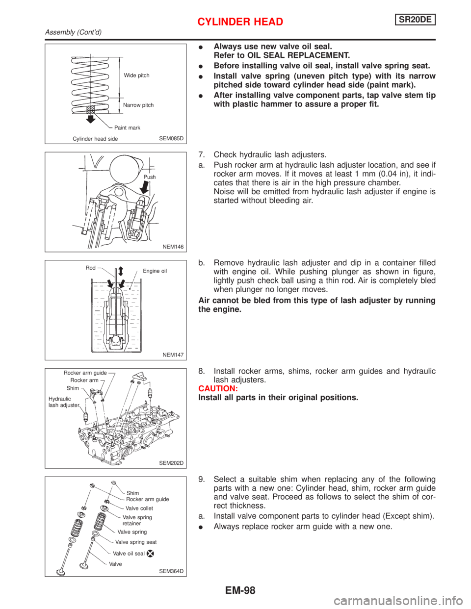
IAlways use new valve oil seal.
Refer to OIL SEAL REPLACEMENT.
IBefore installing valve oil seal, install valve spring seat.
IInstall valve spring (uneven pitch type) with its narrow
pitched side toward cylinder head side (paint mark).
IAfter installing valve component parts, tap valve stem tip
with plastic hammer to assure a proper fit.
7. Check hydraulic lash adjusters.
a. Push rocker arm at hydraulic lash adjuster location, and see if
rocker arm moves. If it moves at least 1 mm (0.04 in), it indi-
cates that there is air in the high pressure chamber.
Noise will be emitted from hydraulic lash adjuster if engine is
started without bleeding air.
b. Remove hydraulic lash adjuster and dip in a container filled
with engine oil. While pushing plunger as shown in figure,
lightly push check ball using a thin rod. Air is completely bled
when plunger no longer moves.
Air cannot be bled from this type of lash adjuster by running
the engine.
8. Install rocker arms, shims, rocker arm guides and hydraulic
lash adjusters.
CAUTION:
Install all parts in their original positions.
9. Select a suitable shim when replacing any of the following
parts with a new one: Cylinder head, shim, rocker arm guide
and valve seat. Proceed as follows to select the shim of cor-
rect thickness.
a. Install valve component parts to cylinder head (Except shim).
IAlways replace rocker arm guide with a new one.
SEM085D Wide pitch
Narrow pitch
Paint mark
Cylinder head side
NEM146 Push
NEM147 Rod
Engine oil
SEM202D Rocker arm guide
Rocker arm
Shim
Hydraulic
lash adjuster
SEM364D Shim
Rocker arm guide
Valve collet
Valve spring
retainer
Valve spring
Valve spring seat
Valve oil sealValve
CYLINDER HEADSR20DE
Assembly (Cont'd)
EM-98