1999 NISSAN PRIMERA heating
[x] Cancel search: heatingPage 36 of 2267
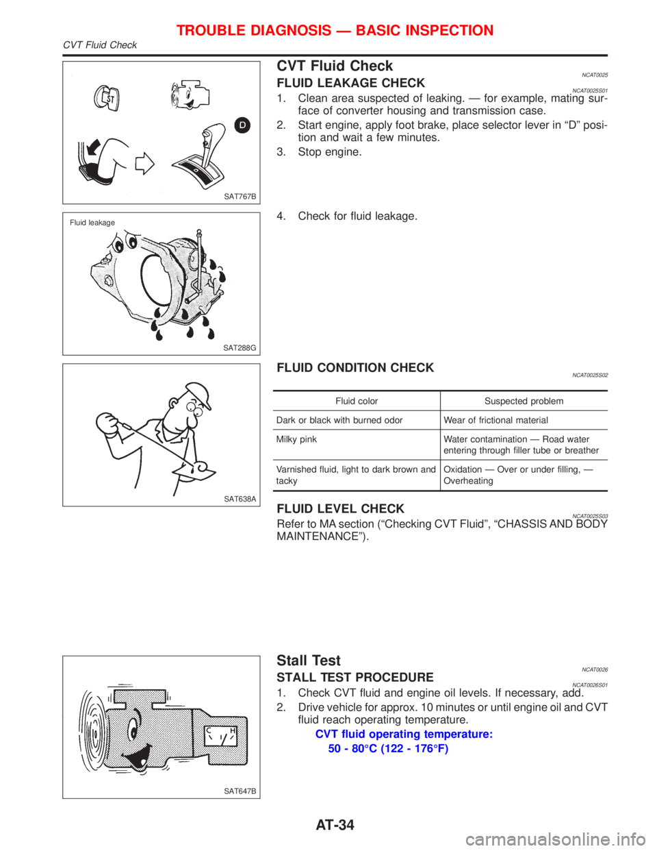
CVT Fluid CheckNCAT0025FLUID LEAKAGE CHECKNCAT0025S011. Clean area suspected of leaking. Ð for example, mating sur-
face of converter housing and transmission case.
2. Start engine, apply foot brake, place selector lever in ªDº posi-
tion and wait a few minutes.
3. Stop engine.
4. Check for fluid leakage.
FLUID CONDITION CHECKNCAT0025S02
Fluid color Suspected problem
Dark or black with burned odor Wear of frictional material
Milky pink Water contamination Ð Road water
entering through filler tube or breather
Varnished fluid, light to dark brown and
tackyOxidation Ð Over or under filling, Ð
Overheating
FLUID LEVEL CHECKNCAT0025S03Refer to MA section (ªChecking CVT Fluidº, ªCHASSIS AND BODY
MAINTENANCEº).
Stall TestNCAT0026STALL TEST PROCEDURENCAT0026S011. Check CVT fluid and engine oil levels. If necessary, add.
2. Drive vehicle for approx. 10 minutes or until engine oil and CVT
fluid reach operating temperature.
CVT fluid operating temperature:
50 - 80ÉC (122 - 176ÉF)
SAT767B
SAT288G Fluid leakage
SAT638A
SAT647B
TROUBLE DIAGNOSIS Ð BASIC INSPECTION
CVT Fluid Check
AT-34
Page 256 of 2267
Heated Seat
lWhen handling seat, be extremely careful not to scratch heating unit.
lTo replace heating unit, seat trim and pad should be separated.
lDo not use any organic solvent, such as thinner, benzene, alcohol, gasoline, etc. to clean trims.
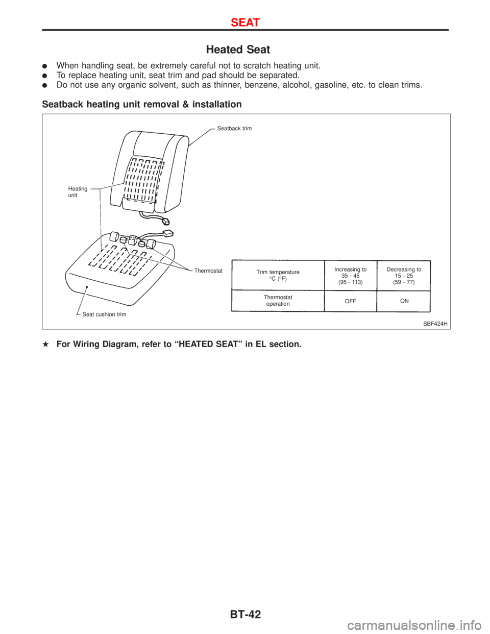
Seatback heating unit removal & installation
HFor Wiring Diagram, refer to ªHEATED SEATº in EL section.
SBF424H Seatback trim
Heating
unit
Thermostat
Seat cushion trimTrim temperature
ÉC (ÉF)
Thermostat
operationIncreasing to
35-45
(95 - 113)
OFFDecreasing to
15-25
(59 - 77)
ON
SEAT
BT-42
Page 336 of 2267
Ð: Not applicable
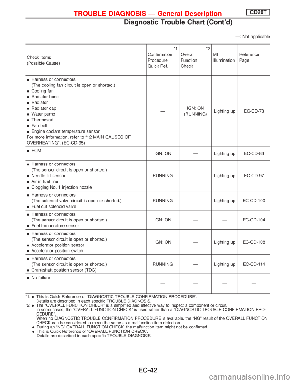
Check Items
(Possible Cause)*1
Confirmation
Procedure
Quick Ref.*2
Overall
Function
CheckMI
IlluminationReference
Page
lHarness or connectors
(The cooling fan circuit is open or shorted.)
lCooling fan
lRadiator hose
lRadiator
lRadiator cap
lWater pump
lThermostat
lFan belt
lEngine coolant temperature sensor
For more information, refer to ª12 MAIN CAUSES OF
OVERHEATINGº. (EC-CD-95)ÐIGN: ON
(RUNNING)Lighting up EC-CD-78
lECM
IGN: ON Ð Lighting up EC-CD-86
lHarness or connectors
(The sensor circuit is open or shorted.)
lNeedle lift sensor
lAir in fuel line
lClogging No. 1 injection nozzleRUNNING Ð Lighting up EC-CD-97
lHarness or connectors
(The solenoid valve circuit is open or shorted.)
lFuel cut solenoid valveRUNNING Ð Lighting up EC-CD-100
lHarness or connectors
(The sensor circuit is open or shorted.)
lFuel temperature sensorIGN: ON Ð Ð EC-CD-104
lHarness or connectors
(The sensor circuit is open or shorted.)
lAccelerator position sensor
lAccelerator position switchIGN: ON Ð Lighting up EC-CD-108
lHarness or connectors
(The sensor circuit is open or shorted.)
lCrankshaft position sensor (TDC)RUNNING Ð Lighting up EC-CD-114
lNo failure
Ð ÐÐÐ
*1:lThis is Quick Reference of ªDIAGNOSTIC TROUBLE CONFIRMATION PROCEDUREº.
Details are described in each specific TROUBLE DIAGNOSIS.
*2:
lThe ªOVERALL FUNCTION CHECKº is a simplified and effective way to inspect a component or circuit.
In some cases, the ªOVERALL FUNCTION CHECKº is used rather than a ªDIAGNOSTIC TROUBLE CONFIRMATION PRO-
CEDUREº.
When no DIAGNOSTIC TROUBLE CONFIRMATION PROCEDURE is available, the ªNGº result of the OVERALL FUNCTION
CHECK can be considered to mean the same as a malfunction item detection.
lDuring an ªNGº OVERALL FUNCTION CHECK, the malfunction item might not be confirmed.lThis is Quick Reference of ªOVERALL FUNCTION CHECKº.
Details are described in each specific TROUBLE DIAGNOSIS.
TROUBLE DIAGNOSIS Ð General DescriptionCD20T
Diagnostic Trouble Chart (Cont'd)
EC-42
Page 381 of 2267
Cooling Fan (Overheat)
SYSTEM DESCRIPTION
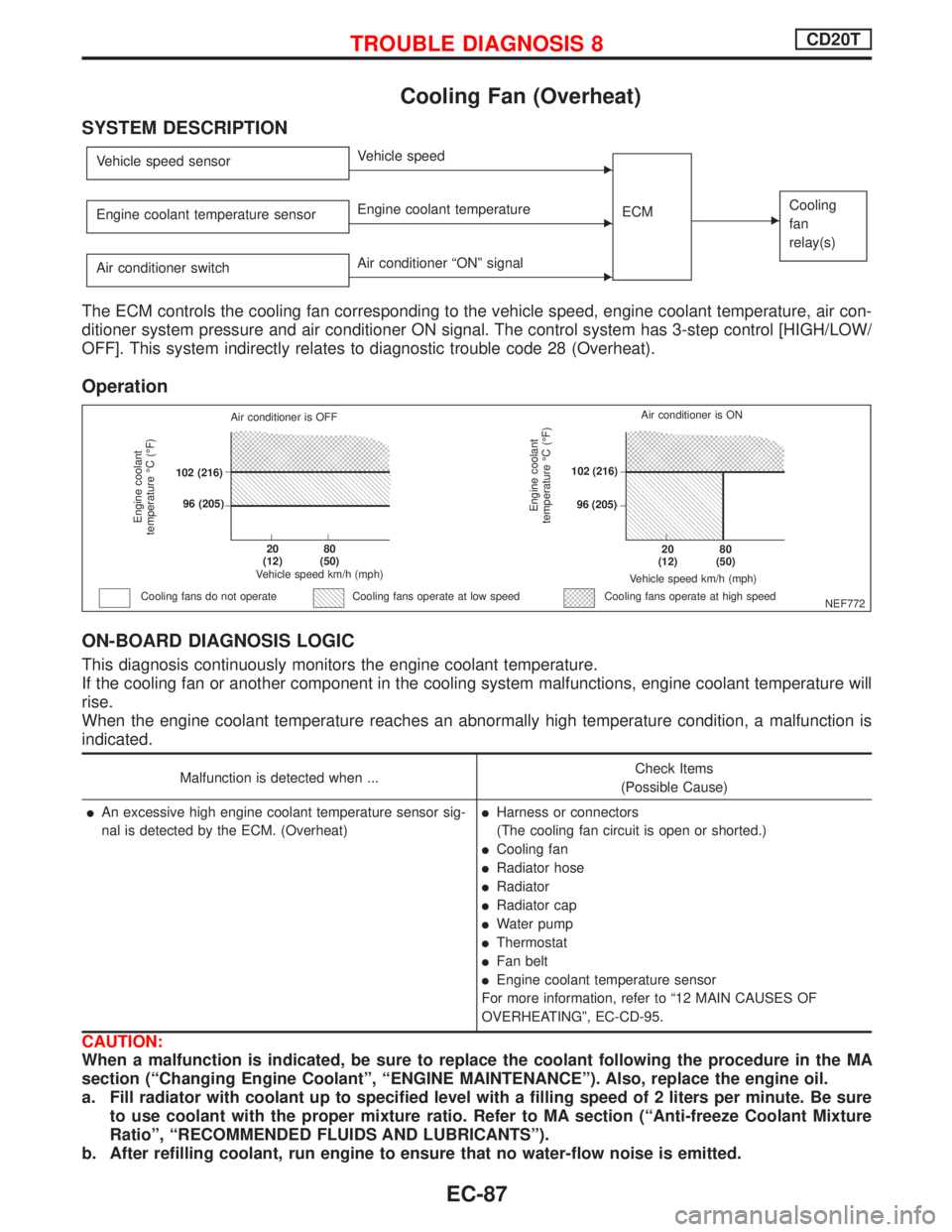
Vehicle speed sensorEVehicle speed
ECM
ECooling
fan
relay(s)Engine coolant temperature sensorEEngine coolant temperature
Air conditioner switch
EAir conditioner ªONº signal
The ECM controls the cooling fan corresponding to the vehicle speed, engine coolant temperature, air con-
ditioner system pressure and air conditioner ON signal. The control system has 3-step control [HIGH/LOW/
OFF]. This system indirectly relates to diagnostic trouble code 28 (Overheat).
Operation
ON-BOARD DIAGNOSIS LOGIC
This diagnosis continuously monitors the engine coolant temperature.
If the cooling fan or another component in the cooling system malfunctions, engine coolant temperature will
rise.
When the engine coolant temperature reaches an abnormally high temperature condition, a malfunction is
indicated.
Malfunction is detected when ...Check Items
(Possible Cause)
lAn excessive high engine coolant temperature sensor sig-
nal is detected by the ECM. (Overheat)lHarness or connectors
(The cooling fan circuit is open or shorted.)
lCooling fan
lRadiator hose
lRadiator
lRadiator cap
lWater pump
lThermostat
lFan belt
lEngine coolant temperature sensor
For more information, refer to ª12 MAIN CAUSES OF
OVERHEATINGº, EC-CD-95.
CAUTION:
When a malfunction is indicated, be sure to replace the coolant following the procedure in the MA
section (ªChanging Engine Coolantº, ªENGINE MAINTENANCEº). Also, replace the engine oil.
a. Fill radiator with coolant up to specified level with a filling speed of 2 liters per minute. Be sure
to use coolant with the proper mixture ratio. Refer to MA section (ªAnti-freeze Coolant Mixture
Ratioº, ªRECOMMENDED FLUIDS AND LUBRICANTSº).
b. After refilling coolant, run engine to ensure that no water-flow noise is emitted.
NEF772
Engine coolant
temperature ÉC (ÉF)
Air conditioner is OFF
.102 (216)
.96 (205)
.20
(12).80
(50)
Vehicle speed km/h (mph)
Cooling fans do not operateCooling fans operate at high speed
Engine coolant
temperature ÉC (ÉF)
Vehicle speed km/h (mph)
.20
(12).80
(50)
.102 (216)
.96 (205)Air conditioner is ON
Cooling fans operate at low speed
TROUBLE DIAGNOSIS 8CD20T
EC-87
Page 388 of 2267
pB
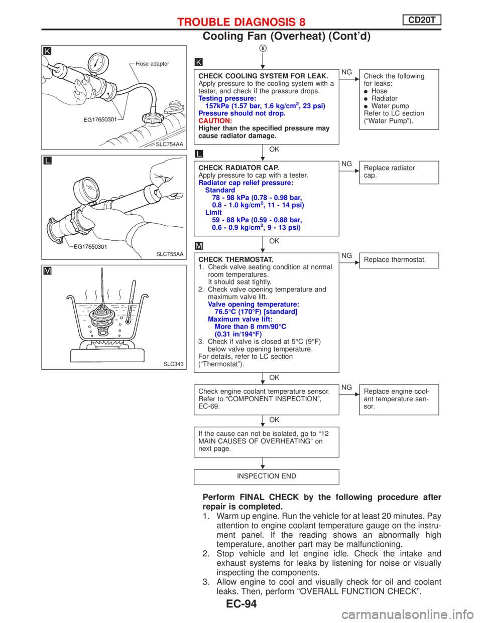
CHECK COOLING SYSTEM FOR LEAK.
Apply pressure to the cooling system with a
tester, and check if the pressure drops.
Testing pressure:
157kPa (1.57 bar, 1.6 kg/cm
2, 23 psi)
Pressure should not drop.
CAUTION:
Higher than the specified pressure may
cause radiator damage.
OK
ENG
Check the following
for leaks:
lHoselRadiatorlWater pump
Refer to LC section
(ªWater Pumpº).
CHECK RADIATOR CAP.
Apply pressure to cap with a tester.
Radiator cap relief pressure:
Standard
78 - 98 kPa (0.78 - 0.98 bar,
0.8 - 1.0 kg/cm
2, 11 - 14 psi)
Limit
59 - 88 kPa (0.59 - 0.88 bar,
0.6 - 0.9 kg/cm
2,9-13psi)
OK
ENG
Replace radiator
cap.
CHECK THERMOSTAT.
1. Check valve seating condition at normal
room temperatures.
It should seat tightly.
2. Check valve opening temperature and
maximum valve lift.
Valve opening temperature:
76.5ÉC (170ÉF) [standard]
Maximum valve lift:
More than 8 mm/90ÉC
(0.31 in/194ÉF)
3. Check if valve is closed at 5ÉC (9ÉF)
below valve opening temperature.
For details, refer to LC section
(ªThermostatº).
OK
ENG
Replace thermostat.
Check engine coolant temperature sensor.
Refer to ªCOMPONENT INSPECTIONº,
EC-69.
OK
ENG
Replace engine cool-
ant temperature sen-
sor.
If the cause can not be isolated, go to ª12
MAIN CAUSES OF OVERHEATINGº on
next page.
INSPECTION END
Perform FINAL CHECK by the following procedure after
repair is completed.
1. Warm up engine. Run the vehicle for at least 20 minutes. Pay
attention to engine coolant temperature gauge on the instru-
ment panel. If the reading shows an abnormally high
temperature, another part may be malfunctioning.
2. Stop vehicle and let engine idle. Check the intake and
exhaust systems for leaks by listening for noise or visually
inspecting the components.
3. Allow engine to cool and visually check for oil and coolant
leaks. Then, perform ªOVERALL FUNCTION CHECKº.
Hose adapter
.SLC754AA
SLC755AA
SLC343
H
H
H
H
H
H
TROUBLE DIAGNOSIS 8CD20T
Cooling Fan (Overheat) (Cont'd)
EC-94
Page 389 of 2267
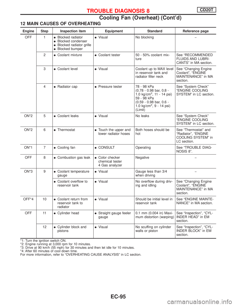
12 MAIN CAUSES OF OVERHEATING
Engine Step Inspection item Equipment Standard Reference page
OFF 1
lBlocked radiatorlBlocked condenserlBlocked radiator grillelBlocked bumper
lVisual No blocking þ
2
lCoolant mixturelCoolant tester 50 - 50% coolant mix-
tureSee ªRECOMMENDED
FLUIDS AND LUBRI-
CANTSº in MA section.
3
lCoolant levellVisual Coolant up to MAX level
in reservoir tank and
radiator filler neckSee ªChanging Engine
Coolantº, ªENGINE
MAINTENANCEº in MA
section.
4
lRadiator caplPressure tester 78 - 98 kPa
(0.78 - 0.98 bar, 0.8 -
1.0 kg/cm
2, 11 - 14 psi)
59-98kPa
(0.59 - 0.98 bar, 0.6 -
1.0 kg/cm
2,9-14psi)
(Limit)See ªSystem Checkº
ªENGINE COOLING
SYSTEMº in LC section.
ON*2 5
lCoolant leakslVisual No leaks See ªSystem Checkº
ªENGINE COOLING
SYSTEMº in LC section.
ON*2 6
lThermostatlTouch the upper and
lower radiator hosesBoth hoses should be
hotSee ªThermostatº and
ªRadiatorº, ªENGINE
COOLING SYSTEMº in
LC section.
ON*1 7
lCooling fanlCONSULT Operating See ªTROUBLE DIAG-
NOSIS 8º.
OFF 8
lCombustion gas leaklColor checker
chemical tester
4 Gas analyzerNegative þ
ON*3 9
lCoolant temperature
gaugelVisual Gauge less than 3/4
when drivingþ
lCoolant overflow to
reservoir tanklVisual No overflow during driv-
ing and idlingSee ªChanging Engine
Coolantº, ªENGINE
MAINTENANCEº in MA
section.
OFF*4 10
lCoolant return from
reservoir tank to
radiatorlVisual Should be initial level in
reservoir tankSee ªENGINE MAINTE-
NANCEº in MA section.
OFF 11
lCylinder headlStraight gauge feeler
gauge0.1 mm (0.004 in) Maxi-
mum distortion (warping)See ªInspectionº, ªCYL-
INDER HEADº in EM
section.
12
lCylinder block and
pistonslVisual No scuffing on cylinder
walls or pistonSee ªInspectionº, ªCYL-
INDER BLOCKº in EM
section.
*1: Turn the ignition switch ON.
*2: Engine running at 3,000 rpm for 10 minutes.
*3: Drive at 90 km/h (55 mph) for 30 minutes and then let idle for 10 minutes.
*4: After 60 minutes of cool down time.
For more information, refer to ªOVERHEATING CAUSE ANALYSISº in LC section.
TROUBLE DIAGNOSIS 8CD20T
Cooling Fan (Overheat) (Cont'd)
EC-95
Page 412 of 2267
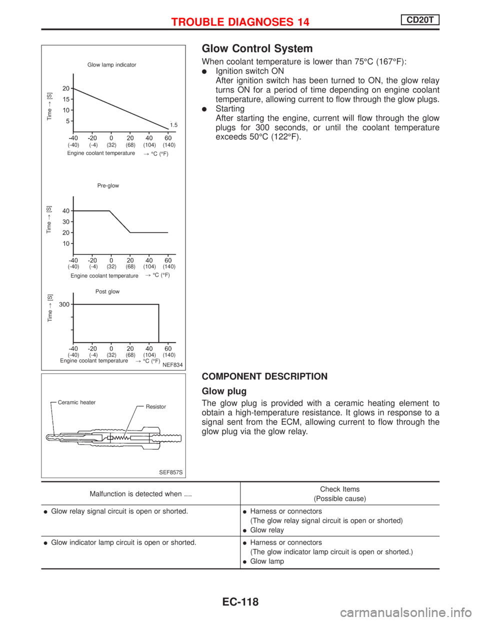
Glow Control System
When coolant temperature is lower than 75ÉC (167ÉF):
lIgnition switch ON
After ignition switch has been turned to ON, the glow relay
turns ON for a period of time depending on engine coolant
temperature, allowing current to flow through the glow plugs.
lStarting
After starting the engine, current will flow through the glow
plugs for 300 seconds, or until the coolant temperature
exceeds 50ÉC (122ÉF).
COMPONENT DESCRIPTION
Glow plug
The glow plug is provided with a ceramic heating element to
obtain a high-temperature resistance. It glows in response to a
signal sent from the ECM, allowing current to flow through the
glow plug via the glow relay.
Malfunction is detected when ....Check Items
(Possible cause)
lGlow relay signal circuit is open or shorted.lHarness or connectors
(The glow relay signal circuit is open or shorted)
lGlow relay
lGlow indicator lamp circuit is open or shorted.lHarness or connectors
(The glow indicator lamp circuit is open or shorted.)
lGlow lamp
Glow lamp indicator
Time,[S]
.
Engine coolant temperature
Pre-glow
Time,[S]
Engine coolant temperature.
Post glow
.Time,[S]
Engine coolant temperature
.1.5
.(-40) (-4) (32) (68) (104) (140)
.(-40) (-4) (32) (68) (104) (140)
.(-40) (-4) (32) (68) (104) (140),ÉC (ÉF).,ÉC (ÉF)
.,ÉC (ÉF)
NEF834
.
.
SEF857S Ceramic heater
Resistor
TROUBLE DIAGNOSES 14CD20T
EC-118
Page 419 of 2267
![NISSAN PRIMERA 1999 Electronic Repair Manual Glow plug
1. Remove glow plug connecting plate.
2. Check each glow plug for continuity.
Continuity should exist:
Approximately 0.5W[at 25ÉC (77ÉF)]
lIf NG, replace glow plug.
3. Install glow plug co NISSAN PRIMERA 1999 Electronic Repair Manual Glow plug
1. Remove glow plug connecting plate.
2. Check each glow plug for continuity.
Continuity should exist:
Approximately 0.5W[at 25ÉC (77ÉF)]
lIf NG, replace glow plug.
3. Install glow plug co](/manual-img/5/57377/w960_57377-418.png)
Glow plug
1. Remove glow plug connecting plate.
2. Check each glow plug for continuity.
Continuity should exist:
Approximately 0.5W[at 25ÉC (77ÉF)]
lIf NG, replace glow plug.
3. Install glow plug connecting plate securely.
lDo not bump glow plug heating element. If it is bumped,
replace glow plug with new one. (If glow plug is dropped
from a height of 0.1 m (3.94 in) or greater, replace with
new one.)
lIf glow plug installation hole is contaminated with
carbon, remove using a reamer or suitable tool.
lHand-tighten glow plug by turning it 2 to 3 times, then
tighten using a tool to specified torque.
: 15 - 20 N´m (1.5 - 2.0 kg-m, 11 - 14 ft-lb)
SEF630K Ohmmeter
SEC565B Glow nut
Glow harness
Connecting
plate
Washer
Spring washer
Glow plug
TROUBLE DIAGNOSES 14CD20T
Glow Control System (Cont'd)
EC-125