1999 NISSAN PRIMERA oil type
[x] Cancel search: oil typePage 125 of 2267
Supplemental Restraint System (SRS) ªAIR
BAGº and ªSEAT BELT PRE-TENSIONERº
The Supplemental Restraint System such as ªAIR BAGº and ªSEAT BELT PRE-TENSIONERº used along
with a seat belt, helps to reduce the risk or severity of injury to the driver and front passenger for certain
types of collision. The SRS system composition which is available to NISSAN MODEL P11 is as follows (The
composition varies according to the destination and optional equipment.):
lFor a frontal collision
The Supplemental Restraint System consists of driver air bag module (located in the center of the
steering wheel), front passenger air bag module (located on the instrument panel on passenger side),
front seat belt pre-tensioners, a diagnosis sensor unit, warning lamp, wiring harness and spiral cable.
lFor a side collision
The Supplemental Restraint System consists of front side air bag module (located in the outer side of
front seat), side air bag (satellite) sensor, diagnosis sensor unit (one of components of air bags for a
frontal collision), wiring harness, warning lamp (one of components of air bags for a frontal collision).
Information necessary to service the system safely is included in theRS sectionof this Service Manual.
WARNING:
lTo avoid rendering the SRS inoperative, which could increase the risk of personal injury or death
in the event of a collision which would result in air bag inflation, all maintenance should be per-
formed by an authorized NISSAN dealer.
lImproper maintenance, including incorrect removal and installation of the SRS, can lead to per-
sonal injury caused by unintentional activation of the system. For removal of Spiral Cable and
Air Bag Module, see the RS section.
lDo not use electrical test equipment on any circuit related to the SRS unless instructed to in this
Service Manual. Spiral cable and wiring harnesses covered with yellow insulation tape either just
before the harness connectors or for the complete harness are related to the SRS.
Precautions for Brake System
lRecommended fluid is brake fluid ªDOT 4º.
lNever reuse drained brake fluid.
lBe careful not to splash brake fluid on painted areas.
lTo clean or wash all parts of master cylinder, disc brake
caliper and wheel cylinder, use clean brake fluid.
lNever use mineral oils such as gasoline or kerosene.
They will ruin rubber parts of the hydraulic system.
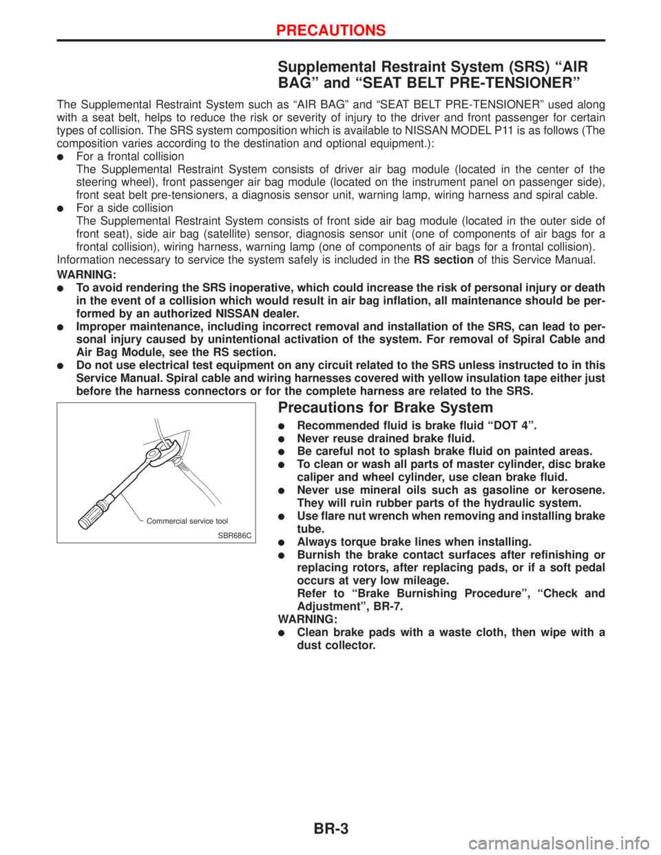
lUse flare nut wrench when removing and installing brake
tube.
lAlways torque brake lines when installing.
lBurnish the brake contact surfaces after refinishing or
replacing rotors, after replacing pads, or if a soft pedal
occurs at very low mileage.
Refer to ªBrake Burnishing Procedureº, ªCheck and
Adjustmentº, BR-7.
WARNING:
lClean brake pads with a waste cloth, then wipe with a
dust collector.
SBR686C Commercial service tool
PRECAUTIONS
BR-3
Page 155 of 2267
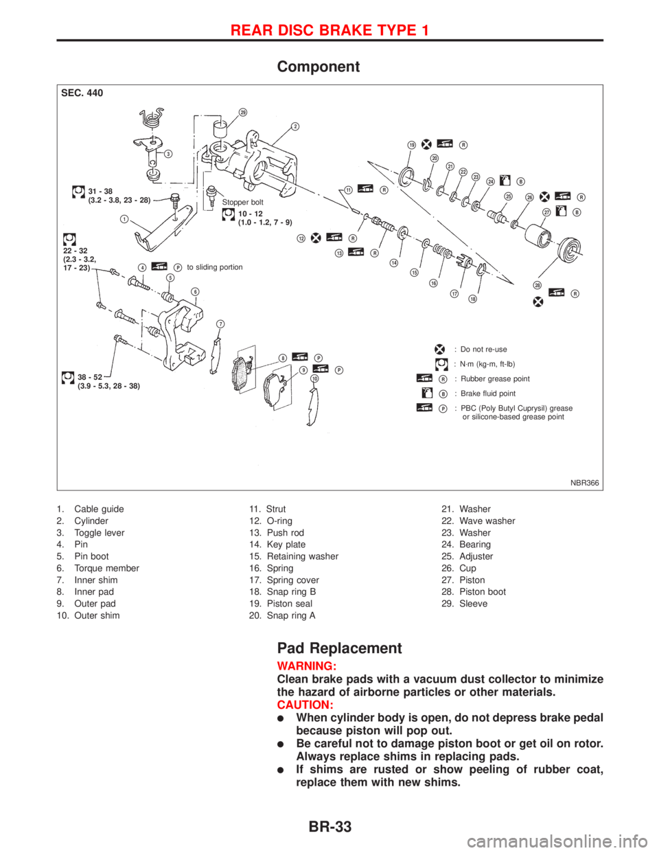
Component
1. Cable guide
2. Cylinder
3. Toggle lever
4. Pin
5. Pin boot
6. Torque member
7. Inner shim
8. Inner pad
9. Outer pad
10. Outer shim11. Strut
12. O-ring
13. Push rod
14. Key plate
15. Retaining washer
16. Spring
17. Spring cover
18. Snap ring B
19. Piston seal
20. Snap ring A21. Washer
22. Wave washer
23. Washer
24. Bearing
25. Adjuster
26. Cup
27. Piston
28. Piston boot
29. Sleeve
Pad Replacement
WARNING:
Clean brake pads with a vacuum dust collector to minimize
the hazard of airborne particles or other materials.
CAUTION:
lWhen cylinder body is open, do not depress brake pedal
because piston will pop out.
lBe careful not to damage piston boot or get oil on rotor.
Always replace shims in replacing pads.
lIf shims are rusted or show peeling of rubber coat,
replace them with new shims.
NBR366
SEC. 440
Stopper bolt
10-12
(1.0-1.2,7-9)
31-38
(3.2 - 3.8, 23 - 28)
p1
22-32
(2.3 - 3.2,
17 - 23)
38-52
(3.9 - 5.3, 28 - 38)p10p9pPp8pP
p7
p6
p5p4pPto sliding portion
p12pR
p13pR
p14
p15
p16
p17p18
p28pR
: Do not re-use
: N´m (kg-m, ft-lb)
pR: Rubber grease point
pB: Brake fluid point
pP: PBC (Poly Butyl Cuprysil) grease
or silicone-based grease point
p23
p27pB
p26pRp25
p24pBp22p21p20
p19pR
p11pR
p3
p2
p29
REAR DISC BRAKE TYPE 1
BR-33
Page 158 of 2267
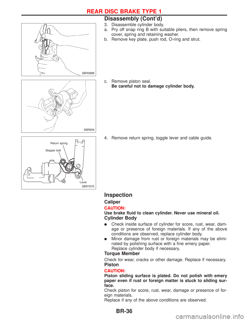
3. Disassemble cylinder body.
a. Pry off snap ring B with suitable pliers, then remove spring
cover, spring and retaining washer.
b. Remove key plate, push rod, O-ring and strut.
c. Remove piston seal.
Be careful not to damage cylinder body.
4. Remove return spring, toggle lever and cable guide.
Inspection
Caliper
CAUTION:
Use brake fluid to clean cylinder. Never use mineral oil.
Cylinder Body
lCheck inside surface of cylinder for score, rust, wear, dam-
age or presence of foreign materials. If any of the above
conditions are observed, replace cylinder body.
lMinor damage from rust or foreign materials may be elimi-
nated by polishing surface with a fine emery paper.
Replace cylinder body if necessary.
Torque Member
Check for wear, cracks or other damage. Replace if necessary.
Piston
CAUTION:
Piston sliding surface is plated. Do not polish with emery
paper even if rust or foreign matter is stuck to sliding sur-
face.
Check piston for score, rust, wear, damage or presence of for-
eign materials.
Replace if any of the above conditions are observed.
SBR088B
SBR656
SBR767E Stopper boltReturn spring
Lever
REAR DISC BRAKE TYPE 1
Disassembly (Cont'd)
BR-36
Page 162 of 2267
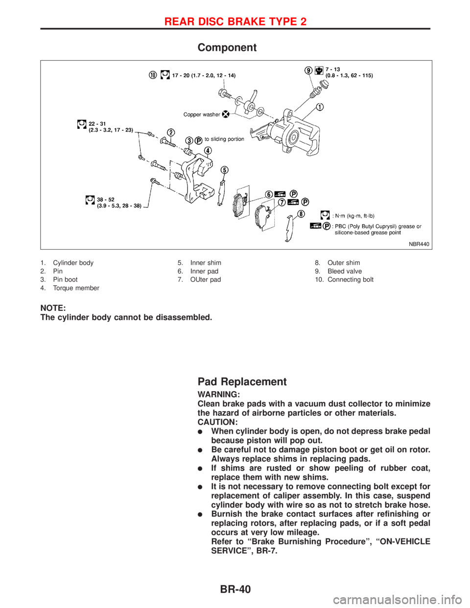
Component
1. Cylinder body
2. Pin
3. Pin boot
4. Torque member5. Inner shim
6. Inner pad
7. OUter pad8. Outer shim
9. Bleed valve
10. Connecting bolt
NOTE:
The cylinder body cannot be disassembled.
Pad Replacement
WARNING:
Clean brake pads with a vacuum dust collector to minimize
the hazard of airborne particles or other materials.
CAUTION:
lWhen cylinder body is open, do not depress brake pedal
because piston will pop out.
lBe careful not to damage piston boot or get oil on rotor.
Always replace shims in replacing pads.
lIf shims are rusted or show peeling of rubber coat,
replace them with new shims.
lIt is not necessary to remove connecting bolt except for
replacement of caliper assembly. In this case, suspend
cylinder body with wire so as not to stretch brake hose.
lBurnish the brake contact surfaces after refinishing or
replacing rotors, after replacing pads, or if a soft pedal
occurs at very low mileage.
Refer to ªBrake Burnishing Procedureº, ªON-VEHICLE
SERVICEº, BR-7.
NBR440
REAR DISC BRAKE TYPE 2
BR-40
Page 299 of 2267
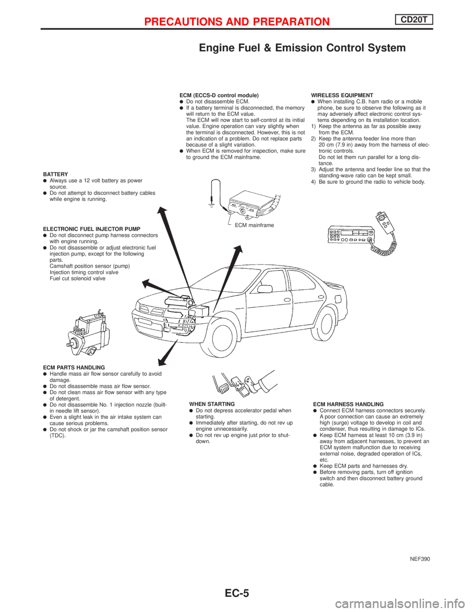
Engine Fuel & Emission Control System
NEF390 ECM (ECCS-D control module)
lDo not disassemble ECM.lIf a battery terminal is disconnected, the memory
will return to the ECM value.
The ECM will now start to self-control at its initial
value. Engine operation can vary slightly when
the terminal is disconnected. However, this is not
an indication of a problem. Do not replace parts
because of a slight variation.
lWhen ECM is removed for inspection, make sure
to ground the ECM mainframe.WIRELESS EQUIPMENT
lWhen installing C.B. ham radio or a mobile
phone, be sure to observe the following as it
may adversely affect electronic control sys-
tems depending on its installation location.
1) Keep the antenna as far as possible away
from the ECM.
2) Keep the antenna feeder line more than
20 cm (7.9 in) away from the harness of elec-
tronic controls.
Do not let them run parallel for a long dis-
tance.
3) Adjust the antenna and feeder line so that the
standing-wave ratio can be kept small.
4) Be sure to ground the radio to vehicle body.
ECM HARNESS HANDLING
lConnect ECM harness connectors securely.
A poor connection can cause an extremely
high (surge) voltage to develop in coil and
condenser, thus resulting in damage to ICs.
lKeep ECM harness at least 10 cm (3.9 in)
away from adjacent harnesses, to prevent an
ECM system malfunction due to receiving
external noise, degraded operation of ICs,
etc.
lKeep ECM parts and harnesses dry.lBefore removing parts, turn off ignition
switch and then disconnect battery ground
cable. WHEN STARTING
lDo not depress accelerator pedal when
starting.
lImmediately after starting, do not rev up
engine unnecessarily.
lDo not rev up engine just prior to shut-
down. ECM PARTS HANDLING
lHandle mass air flow sensor carefully to avoid
damage.
lDo not disassemble mass air flow sensor.lDo not clean mass air flow sensor with any type
of detergent.
lDo not disassemble No. 1 injection nozzle (built-
in needle lift sensor).
lEven a slight leak in the air intake system can
cause serious problems.
lDo not shock or jar the camshaft position sensor
(TDC). ELECTRONIC FUEL INJECTOR PUMP
lDo not disconnect pump harness connectors
with engine running.
lDo not disassemble or adjust electronic fuel
injection pump, except for the following
parts.
Camshaft position sensor (pump)
Injection timing control valve
Fuel cut solenoid valve BATTERY
lAlways use a 12 volt battery as power
source.
lDo not attempt to disconnect battery cables
while engine is running.
ECM mainframe
PRECAUTIONS AND PREPARATIONCD20T
EC-5
Page 667 of 2267

6 CHECK IGNITION SPARK
1. Turn Ignition switch ªOFFº.
2. Disconnect ignition coil assembly from rocker cover.
3. Connect a known good spark plug to the ignition coil assembly.
4. Place end of spark plug against a suitable ground and crank engine.
5. Check for spark.
SEF575Q
OK or NG
OK©GO TO 7.
NG©Check ignition coil, power transistor and their circuits. Refer to EC-QG-323.
7 CHECK SPARK PLUGS
Remove the spark plugs and check for fouling, etc.
SEF156I
OK or NG
OK©GO TO 8.
NG©Repair or replace spark plug(s) with standard type one(s). For spark plug type, refer to
ªENGINE MAINTENANCEº in MA section.
8 CHECK COMPRESSION PRESSURE
Refer to EM section.
ICheck compression pressure.
Standard:
1,324 kPa (13.24 bar, 13.5 kg/cm
2, 192 psi)/350 rpm
Minimum:
1,128 kPa (11.28 bar, 11.5 kg/cm
2, 164 psi)/350 rpm
Difference between each cylinder:
98 kPa (0.98 bar, 1.0 kg/cm
2, 14 psi)/350 rpm
OK or NG
OK©GO TO 9.
NG©Check pistons, piston rings, valves, valve seats and cylinder head gaskets.
DTC P0300 - P0304 NO.4-1CYLINDER MISFIRE,
MULTIPLE CYLINDER MISFIREQG16I18DE
Diagnostic Procedure (Cont'd)
EC-225
Page 1156 of 2267
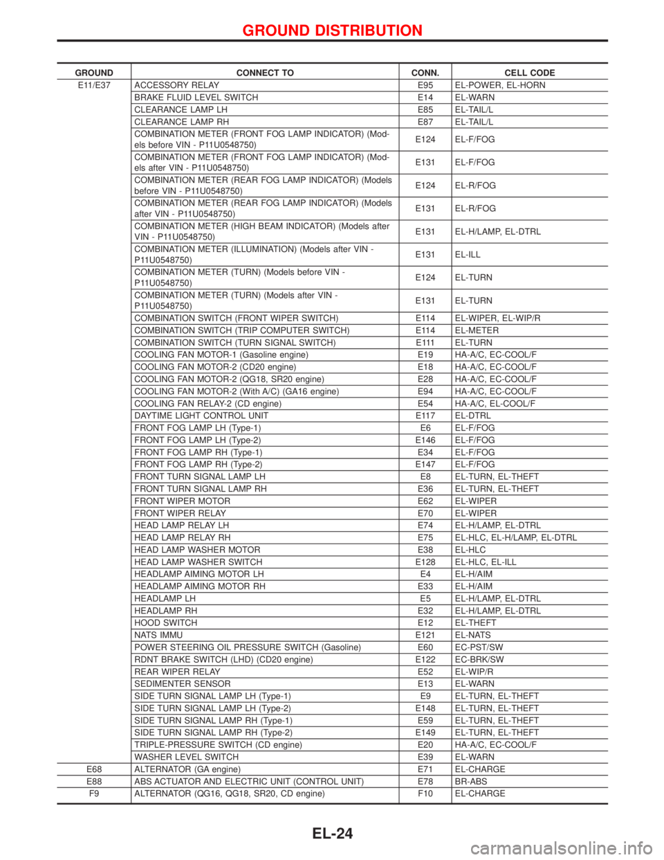
GROUND CONNECT TO CONN. CELL CODE
E11/E37 ACCESSORY RELAY E95 EL-POWER, EL-HORN
BRAKE FLUID LEVEL SWITCH E14 EL-WARN
CLEARANCE LAMP LH E85 EL-TAIL/L
CLEARANCE LAMP RH E87 EL-TAIL/L
COMBINATION METER (FRONT FOG LAMP INDICATOR) (Mod-
els before VIN - P11U0548750)E124 EL-F/FOG
COMBINATION METER (FRONT FOG LAMP INDICATOR) (Mod-
els after VIN - P11U0548750)E131 EL-F/FOG
COMBINATION METER (REAR FOG LAMP INDICATOR) (Models
before VIN - P11U0548750)E124 EL-R/FOG
COMBINATION METER (REAR FOG LAMP INDICATOR) (Models
after VIN - P11U0548750)E131 EL-R/FOG
COMBINATION METER (HIGH BEAM INDICATOR) (Models after
VIN - P11U0548750)E131 EL-H/LAMP, EL-DTRL
COMBINATION METER (ILLUMINATION) (Models after VIN -
P11U0548750)E131 EL-ILL
COMBINATION METER (TURN) (Models before VIN -
P11U0548750)E124 EL-TURN
COMBINATION METER (TURN) (Models after VIN -
P11U0548750)E131 EL-TURN
COMBINATION SWITCH (FRONT WIPER SWITCH) E114 EL-WIPER, EL-WIP/R
COMBINATION SWITCH (TRIP COMPUTER SWITCH) E114 EL-METER
COMBINATION SWITCH (TURN SIGNAL SWITCH) E111 EL-TURN
COOLING FAN MOTOR-1 (Gasoline engine) E19 HA-A/C, EC-COOL/F
COOLING FAN MOTOR-2 (CD20 engine) E18 HA-A/C, EC-COOL/F
COOLING FAN MOTOR-2 (QG18, SR20 engine) E28 HA-A/C, EC-COOL/F
COOLING FAN MOTOR-2 (With A/C) (GA16 engine) E94 HA-A/C, EC-COOL/F
COOLING FAN RELAY-2 (CD engine) E54 HA-A/C, EL-COOL/F
DAYTIME LIGHT CONTROL UNIT E117 EL-DTRL
FRONT FOG LAMP LH (Type-1) E6 EL-F/FOG
FRONT FOG LAMP LH (Type-2) E146 EL-F/FOG
FRONT FOG LAMP RH (Type-1) E34 EL-F/FOG
FRONT FOG LAMP RH (Type-2) E147 EL-F/FOG
FRONT TURN SIGNAL LAMP LH E8 EL-TURN, EL-THEFT
FRONT TURN SIGNAL LAMP RH E36 EL-TURN, EL-THEFT
FRONT WIPER MOTOR E62 EL-WIPER
FRONT WIPER RELAY E70 EL-WIPER
HEAD LAMP RELAY LH E74 EL-H/LAMP, EL-DTRL
HEAD LAMP RELAY RH E75 EL-HLC, EL-H/LAMP, EL-DTRL
HEAD LAMP WASHER MOTOR E38 EL-HLC
HEAD LAMP WASHER SWITCH E128 EL-HLC, EL-ILL
HEADLAMP AIMING MOTOR LH E4 EL-H/AIM
HEADLAMP AIMING MOTOR RH E33 EL-H/AIM
HEADLAMP LH E5 EL-H/LAMP, EL-DTRL
HEADLAMP RH E32 EL-H/LAMP, EL-DTRL
HOOD SWITCH E12 EL-THEFT
NATS IMMU E121 EL-NATS
POWER STEERING OIL PRESSURE SWITCH (Gasoline) E60 EC-PST/SW
RDNT BRAKE SWITCH (LHD) (CD20 engine) E122 EC-BRK/SW
REAR WIPER RELAY E52 EL-WIP/R
SEDIMENTER SENSOR E13 EL-WARN
SIDE TURN SIGNAL LAMP LH (Type-1) E9 EL-TURN, EL-THEFT
SIDE TURN SIGNAL LAMP LH (Type-2) E148 EL-TURN, EL-THEFT
SIDE TURN SIGNAL LAMP RH (Type-1) E59 EL-TURN, EL-THEFT
SIDE TURN SIGNAL LAMP RH (Type-2) E149 EL-TURN, EL-THEFT
TRIPLE-PRESSURE SWITCH (CD engine) E20 HA-A/C, EC-COOL/F
WASHER LEVEL SWITCH E39 EL-WARN
E68 ALTERNATOR (GA engine) E71 EL-CHARGE
E88 ABS ACTUATOR AND ELECTRIC UNIT (CONTROL UNIT) E78 BR-ABS
F9 ALTERNATOR (QG16, QG18, SR20, CD engine) F10 EL-CHARGE
GROUND DISTRIBUTION
EL-24
Page 1157 of 2267
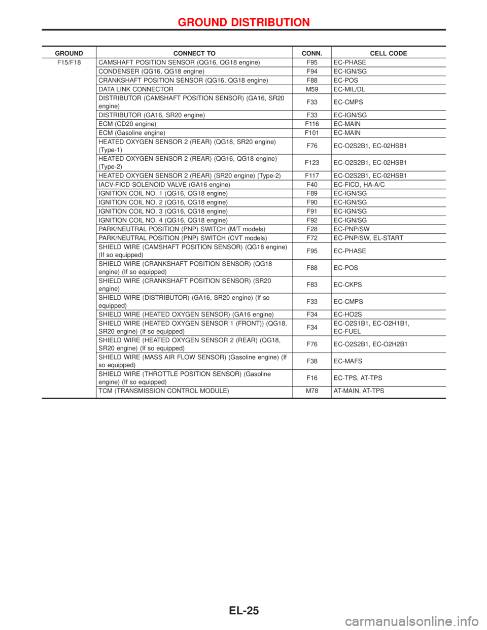
GROUND CONNECT TO CONN. CELL CODE
F15/F18 CAMSHAFT POSITION SENSOR (QG16, QG18 engine) F95 EC-PHASE
CONDENSER (QG16, QG18 engine) F94 EC-IGN/SG
CRANKSHAFT POSITION SENSOR (QG16, QG18 engine) F88 EC-POS
DATA LINK CONNECTOR M59 EC-MIL/DL
DISTRIBUTOR (CAMSHAFT POSITION SENSOR) (GA16, SR20
engine)F33 EC-CMPS
DISTRIBUTOR (GA16, SR20 engine) F33 EC-IGN/SG
ECM (CD20 engine) F116 EC-MAIN
ECM (Gasoline engine) F101 EC-MAIN
HEATED OXYGEN SENSOR 2 (REAR) (QG18, SR20 engine)
(Type-1)F76 EC-O2S2B1, EC-02HSB1
HEATED OXYGEN SENSOR 2 (REAR) (QG16, QG18 engine)
(Type-2)F123 EC-O2S2B1, EC-02HSB1
HEATED OXYGEN SENSOR 2 (REAR) (SR20 engine) (Type-2) F117 EC-O2S2B1, EC-02HSB1
IACV-FICD SOLENOID VALVE (GA16 engine) F40 EC-FICD, HA-A/C
IGNITION COIL NO. 1 (QG16, QG18 engine) F89 EC-IGN/SG
IGNITION COIL NO. 2 (QG16, QG18 engine) F90 EC-IGN/SG
IGNITION COIL NO. 3 (QG16, QG18 engine) F91 EC-IGN/SG
IGNITION COIL NO. 4 (QG16, QG18 engine) F92 EC-IGN/SG
PARK/NEUTRAL POSITION (PNP) SWITCH (M/T models) F28 EC-PNP/SW
PARK/NEUTRAL POSITION (PNP) SWITCH (CVT models) F72 EC-PNP/SW, EL-START
SHIELD WIRE (CAMSHAFT POSITION SENSOR) (QG18 engine)
(If so equipped)F95 EC-PHASE
SHIELD WIRE (CRANKSHAFT POSITION SENSOR) (QG18
engine) (If so equipped)F88 EC-POS
SHIELD WIRE (CRANKSHAFT POSITION SENSOR) (SR20
engine)F83 EC-CKPS
SHIELD WIRE (DISTRIBUTOR) (GA16, SR20 engine) (If so
equipped)F33 EC-CMPS
SHIELD WIRE (HEATED OXYGEN SENSOR) (GA16 engine) F34 EC-HO2S
SHIELD WIRE (HEATED OXYGEN SENSOR 1 (FRONT)) (QG18,
SR20 engine) (If so equipped)F34EC-O2S1B1, EC-O2H1B1,
EC-FUEL
SHIELD WIRE (HEATED OXYGEN SENSOR 2 (REAR) (QG18,
SR20 engine) (If so equipped)F76 EC-O2S2B1, EC-O2H2B1
SHIELD WIRE (MASS AIR FLOW SENSOR) (Gasoline engine) (If
so equipped)F38 EC-MAFS
SHIELD WIRE (THROTTLE POSITION SENSOR) (Gasoline
engine) (If so equipped)F16 EC-TPS, AT-TPS
TCM (TRANSMISSION CONTROL MODULE) M78 AT-MAIN, AT-TPS
GROUND DISTRIBUTION
EL-25