1999 NISSAN PRIMERA seat memory
[x] Cancel search: seat memoryPage 2211 of 2267

Trouble Diagnoses Introduction
CAUTION:
lDo not use electrical test equipment on any circuit related to the SRS unless instructed to in this
Service Manual. Spiral cable and SRS wiring harnesses (except ªSEAT BELT PRE-TENSIONER
CONNECTORº) can be identified by yellow harness connector (and with yellow harness protec-
tor or yellow insulation tape before the harness connectors.
lDo not attempt to repair, splice or modify the SRS wiring harness. If the harness is damaged,
replace it with a new one.
lKeep ground portion clean.
DIAGNOSIS FUNCTION
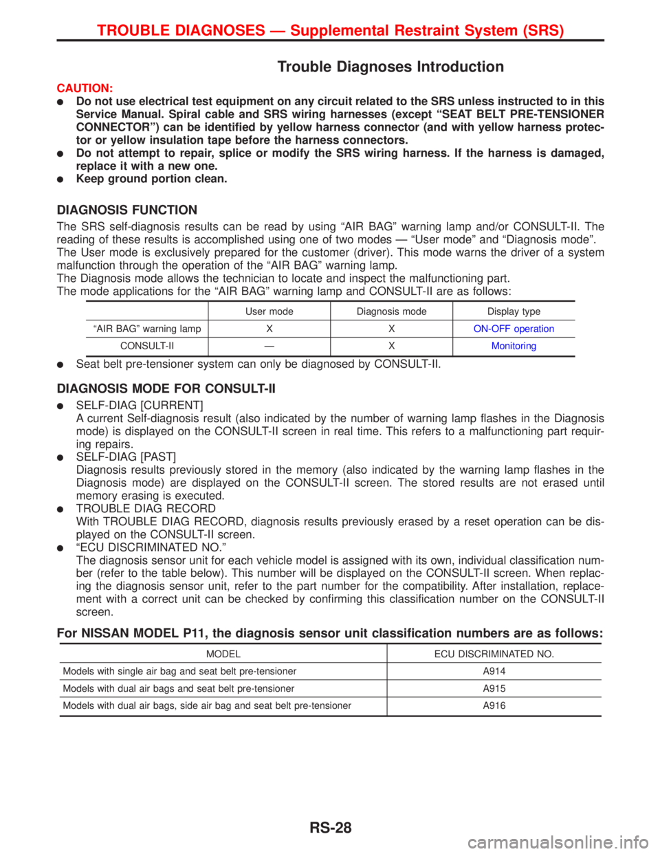
The SRS self-diagnosis results can be read by using ªAIR BAGº warning lamp and/or CONSULT-II. The
reading of these results is accomplished using one of two modes Ð ªUser modeº and ªDiagnosis modeº.
The User mode is exclusively prepared for the customer (driver). This mode warns the driver of a system
malfunction through the operation of the ªAIR BAGº warning lamp.
The Diagnosis mode allows the technician to locate and inspect the malfunctioning part.
The mode applications for the ªAIR BAGº warning lamp and CONSULT-II are as follows:
User mode Diagnosis mode Display type
ªAIR BAGº warning lamp X XON-OFF operation
CONSULT-II Ð XMonitoring
lSeat belt pre-tensioner system can only be diagnosed by CONSULT-II.
DIAGNOSIS MODE FOR CONSULT-II
lSELF-DIAG [CURRENT]
A current Self-diagnosis result (also indicated by the number of warning lamp flashes in the Diagnosis
mode) is displayed on the CONSULT-II screen in real time. This refers to a malfunctioning part requir-
ing repairs.
lSELF-DIAG [PAST]
Diagnosis results previously stored in the memory (also indicated by the warning lamp flashes in the
Diagnosis mode) are displayed on the CONSULT-II screen. The stored results are not erased until
memory erasing is executed.
lTROUBLE DIAG RECORD
With TROUBLE DIAG RECORD, diagnosis results previously erased by a reset operation can be dis-
played on the CONSULT-II screen.
lªECU DISCRIMINATED NO.º
The diagnosis sensor unit for each vehicle model is assigned with its own, individual classification num-
ber (refer to the table below). This number will be displayed on the CONSULT-II screen. When replac-
ing the diagnosis sensor unit, refer to the part number for the compatibility. After installation, replace-
ment with a correct unit can be checked by confirming this classification number on the CONSULT-II
screen.
For NISSAN MODEL P11, the diagnosis sensor unit classification numbers are as follows:
MODEL ECU DISCRIMINATED NO.
Models with single air bag and seat belt pre-tensioner A914
Models with dual air bags and seat belt pre-tensioner A915
Models with dual air bags, side air bag and seat belt pre-tensioner A916
TROUBLE DIAGNOSES Ð Supplemental Restraint System (SRS)
RS-28
Page 2232 of 2267

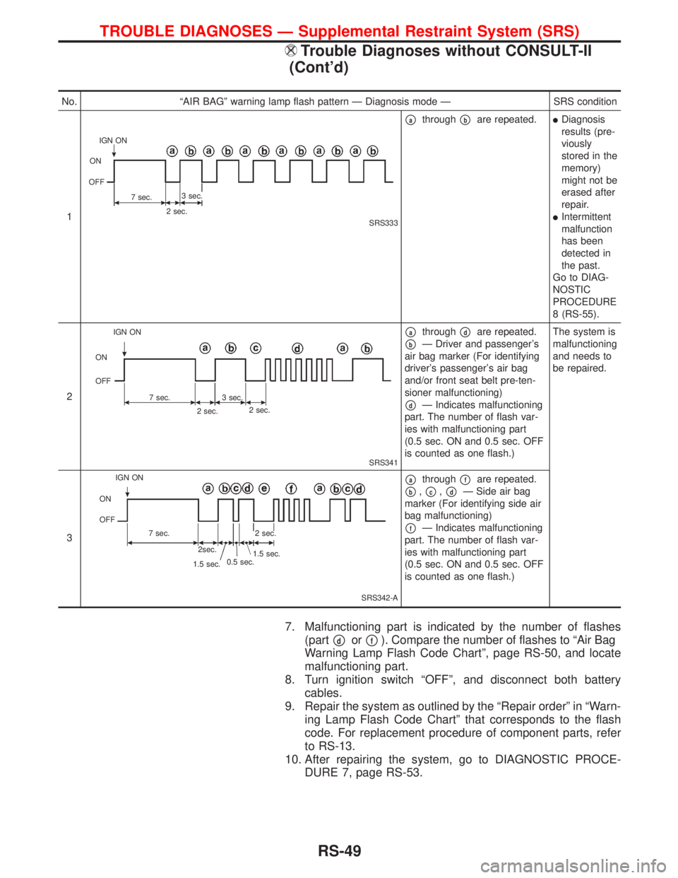
7. Malfunctioning part is indicated by the number of flashes
(part
pdorpf). Compare the number of flashes to ªAir Bag
Warning Lamp Flash Code Chartº, page RS-50, and locate
malfunctioning part.
8. Turn ignition switch ªOFFº, and disconnect both battery
cables.
9. Repair the system as outlined by the ªRepair orderº in ªWarn-
ing Lamp Flash Code Chartº that corresponds to the flash
code. For replacement procedure of component parts, refer
to RS-13.
10. After repairing the system, go to DIAGNOSTIC PROCE-
DURE 7, page RS-53.
No. ªAIR BAGº warning lamp flash pattern Ð Diagnosis mode Ð SRS condition
1
SRS333
pathroughpbare repeated.lDiagnosis
results (pre-
viously
stored in the
memory)
might not be
erased after
repair.
lIntermittent
malfunction
has been
detected in
the past.
Go to DIAG-
NOSTIC
PROCEDURE
8 (RS-55).
2
SRS341
pathroughpdare repeated.
pbÐ Driver and passenger's
air bag marker (For identifying
driver's passenger's air bag
and/or front seat belt pre-ten-
sioner malfunctioning)
pdÐ Indicates malfunctioning
part. The number of flash var-
ies with malfunctioning part
(0.5 sec. ON and 0.5 sec. OFF
is counted as one flash.)The system is
malfunctioning
and needs to
be repaired.
3
SRS342-A
pathroughpfare repeated.
pb,pc,pdÐ Side air bag
marker (For identifying side air
bag malfunctioning)
pfÐ Indicates malfunctioning
part. The number of flash var-
ies with malfunctioning part
(0.5 sec. ON and 0.5 sec. OFF
is counted as one flash.)
IGN ON
ON
OFF
7 sec.3 sec.
2 sec.
IGN ON
ON
OFF
7 sec.3 sec.
2 sec.2 sec.
0.5 sec.
1.5 sec. IGN ON
ON
OFF
7 sec.
2sec.
1.5 sec.2 sec.
TROUBLE DIAGNOSES Ð Supplemental Restraint System (SRS)
Trouble Diagnoses without CONSULT-II
(Cont'd)
RS-49
Page 2237 of 2267

NOTE:
When diagnosis sensor unit is replaced with a new one,
ªAIR BAGº warning lamp will operate in User mode. Check-
ing ªAIR BAGº warning lamp operation in Diagnosis mode
is not required. Go to step 6.
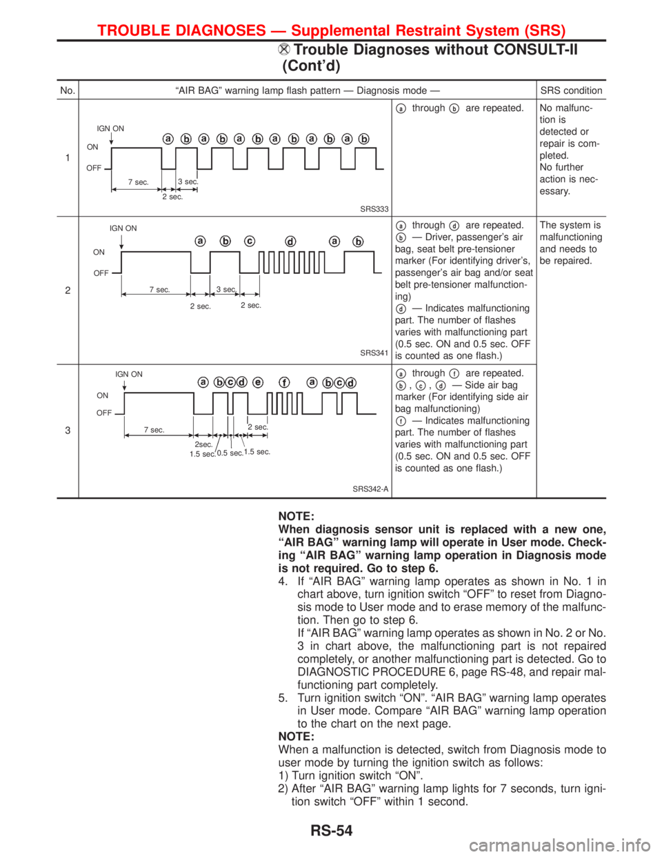
4. If ªAIR BAGº warning lamp operates as shown in No. 1 in
chart above, turn ignition switch ªOFFº to reset from Diagno-
sis mode to User mode and to erase memory of the malfunc-
tion. Then go to step 6.
If ªAIR BAGº warning lamp operates as shown in No. 2 or No.
3 in chart above, the malfunctioning part is not repaired
completely, or another malfunctioning part is detected. Go to
DIAGNOSTIC PROCEDURE 6, page RS-48, and repair mal-
functioning part completely.
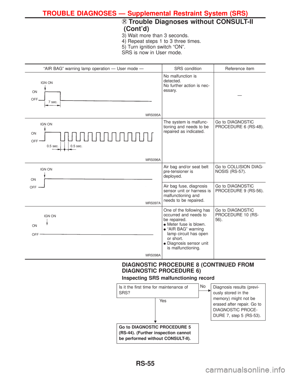
5. Turn ignition switch ªONº. ªAIR BAGº warning lamp operates
in User mode. Compare ªAIR BAGº warning lamp operation
to the chart on the next page.
NOTE:
When a malfunction is detected, switch from Diagnosis mode to
user mode by turning the ignition switch as follows:
1) Turn ignition switch ªONº.
2) After ªAIR BAGº warning lamp lights for 7 seconds, turn igni-
tion switch ªOFFº within 1 second.
No. ªAIR BAGº warning lamp flash pattern Ð Diagnosis mode Ð SRS condition
1
SRS333
pathroughpbare repeated. No malfunc-
tion is
detected or
repair is com-
pleted.
No further
action is nec-
essary.
2
SRS341
pathroughpdare repeated.
pbÐ Driver, passenger's air
bag, seat belt pre-tensioner
marker (For identifying driver's,
passenger's air bag and/or seat
belt pre-tensioner malfunction-
ing)
pdÐ Indicates malfunctioning
part. The number of flashes
varies with malfunctioning part
(0.5 sec. ON and 0.5 sec. OFF
is counted as one flash.)The system is
malfunctioning
and needs to
be repaired.
3
SRS342-A
pathroughpfare repeated.
pb,pc,pdÐ Side air bag
marker (For identifying side air
bag malfunctioning)
pfÐ Indicates malfunctioning
part. The number of flashes
varies with malfunctioning part
(0.5 sec. ON and 0.5 sec. OFF
is counted as one flash.)
IGN ON
ON
OFF
7 sec.3 sec.
2 sec.
IGN ON
ON
OFF
7 sec.3 sec.
2 sec.2 sec.
0.5 sec.
1.5 sec. IGN ON
ON
OFF
7 sec.
2sec.
1.5 sec.2 sec.
TROUBLE DIAGNOSES Ð Supplemental Restraint System (SRS)
Trouble Diagnoses without CONSULT-II
(Cont'd)
RS-54
Page 2238 of 2267

3) Wait more than 3 seconds.
4) Repeat steps 1 to 3 three times.
5) Turn ignition switch ªONº.
SRS is now in User mode.
DIAGNOSTIC PROCEDURE 8 (CONTINUED FROM
DIAGNOSTIC PROCEDURE 6)
Inspecting SRS malfunctioning record
Is it the first time for maintenance of
SRS?
Ye s
ENo
Diagnosis results (previ-
ously stored in the
memory) might not be
erased after repair. Go to
DIAGNOSTIC PROCE-
DURE 7, step 5 (RS-53).
Go to DIAGNOSTIC PROCEDURE 5
(RS-44). (Further inspection cannot
be performed without CONSULT-II).
ªAIR BAGº warning lamp operation Ð User mode Ð SRS condition Reference item
MRS095A
No malfunction is
detected.
No further action is nec-
essary.
Ð
MRS096A
The system is malfunc-
tioning and needs to be
repaired as indicated.Go to DIAGNOSTIC
PROCEDURE 6 (RS-48).
MRS097A
Air bag and/or seat belt
pre-tensioner is
deployed.Go to COLLISION DIAG-
NOSIS (RS-57).
Air bag fuse, diagnosis
sensor unit or harness is
malfunctioning and
needs to be repaired.Go to DIAGNOSTIC
PROCEDURE 9 (RS-56).
MRS098A
One of the following has
occurred and needs to
be repaired.
lMeter fuse is blown.lªAIR BAGº warning
lamp circuit has open
or short.
lDiagnosis sensor unit
is malfunctioning.Go to DIAGNOSTIC
PROCEDURE 10 (RS-
56).
IGN ON
ON
OFF
7 sec.
IGN ON
ON
OFF
0.5 sec. 0.5 sec.
IGN ON
ON
OFF
IGN ON
ON
OFF
H
TROUBLE DIAGNOSES Ð Supplemental Restraint System (SRS)
Trouble Diagnoses without CONSULT-II
(Cont'd)
RS-55