1999 NISSAN PRIMERA change time
[x] Cancel search: change timePage 2 of 2267
FOREWORD
This manual contains maintenance and repair procedures for NISSAN
PRIMERA, model P11-144 series.
In order to assure your safety and the efficient functioning of the vehicle,
this manual should be read thoroughly. It is especially important that the
PRECAUTIONS in the GI section be completely understood before starting
any repair task.
All information in this manual is based on the latest product information
at the time of publication. The right is reserved to make changes in speci-
fications and methods at any time without notice.
IMPORTANT SAFETY NOTICE
The proper performance of service is essential for both the safety of the
technician and the efficient functioning of the vehicle.
The service methods in this Service Manual are described in such a man-
ner that the service may be performed safely and accurately.
Service varies with the procedures used, the skills of the technician and the
tools and parts available. Accordingly, anyone using service procedures,
tools or parts which are not specifically recommended by NISSAN must
first completely satisfy himself that neither his safety nor the vehicle's
safety will be jeopardized by the service method selected.
NISSAN EUROPE N.V.
Service Operations Section
Amsterdam, The Netherlands
Page 44 of 2267
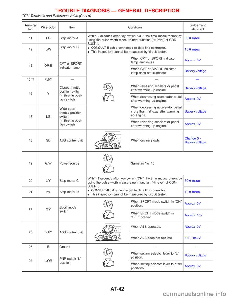
Terminal
No.Wire color Item ConditionJudgement
standard
11 PU Step motor AWithin 2 seconds after key switch ªONº, the time measurement by
using the pulse width measurement function (Hi level) of CON-
SULT-II.
ICONSULT-II cable connected to data link connector.
IThis inspection cannot be measured by circuit tester.30.0 msec
12 L/WStep motor B
10.0 msec
13 OR/BCVT or SPORT
indicator lamp
When CVT or SPORT indicator
lamp illuminatesApprox. 0V
When CVT or SPORT indicator
lamp does not illuminateBattery voltage
15 *1 PU/Y Ð ÐÐ
16 YClosed throttle
position switch
(in throttle posi-
tion switch)When releasing accelerator pedal
after warming up engine.Battery voltage
When depressing accelerator pedal
after warming up engine.Approx. 0V
17 LGWide open
throttle position
switch
(in throttle posi-
tion switch)When depressing accelerator pedal
more than half-way after warming
up engine.Battery voltage
When releasing accelerator pedal
after warming up engine.Approx. 0V
18 SB ABS control unit
When driving slowly.Change 0 -
Battery voltage
19 G/W Power source
Same as No. 10
20 L/Y Step motor CWithin 2 seconds after key switch ªONº, the time measurement by
using the pulse width measurement function (Hi level) of CON-
SULT-II.
ICONSULT-II cable connected to data link connector.
IThis inspection cannot be measured by circuit tester.30.0 msec
21 P/L Step motor D10.0 msec.
22 GYSport mode
switch
When SPORT mode switch in ªONº
position.Approx. 0V
When SPORT mode switch in
ªOFFº position.Approx. 10V
23 BR/Y ABS control unit
When ABS operates.Approx. 0V
When ABS does not operate.5.6 - 10.0V
25 B Ground
ÐÐ
27 L/ORPNP switch ªLº
positionWhen setting selector lever to ªLº
position.Battery voltage
When setting selector lever to other
positions.Approx. 0V
TROUBLE DIAGNOSIS Ð GENERAL DESCRIPTION
TCM Terminals and Reference Value (Cont'd)
AT-42
Page 88 of 2267
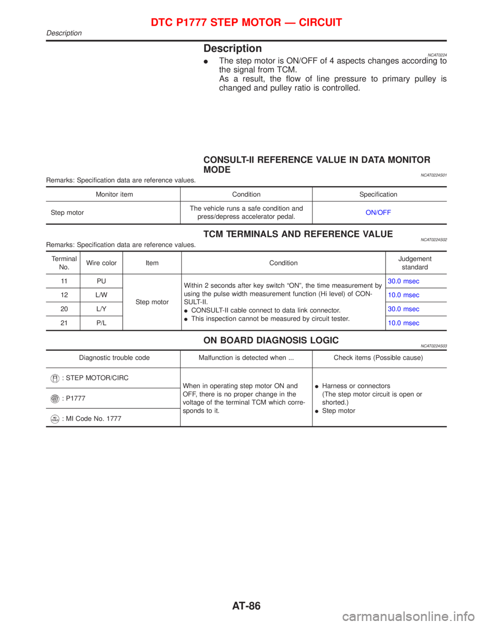
DescriptionNCAT0224IThe step motor is ON/OFF of 4 aspects changes according to
the signal from TCM.
As a result, the flow of line pressure to primary pulley is
changed and pulley ratio is controlled.
CONSULT-II REFERENCE VALUE IN DATA MONITOR
MODE
NCAT0224S01Remarks: Specification data are reference values.
Monitor item Condition Specification
Step motorThe vehicle runs a safe condition and
press/depress accelerator pedal.ON/OFF
TCM TERMINALS AND REFERENCE VALUENCAT0224S02Remarks: Specification data are reference values.
Terminal
No.Wire color Item ConditionJudgement
standard
11 P U
Step motorWithin 2 seconds after key switch ªONº, the time measurement by
using the pulse width measurement function (Hi level) of CON-
SULT-II.
ICONSULT-II cable connect to data link connector.
IThis inspection cannot be measured by circuit tester.30.0 msec
12 L/W10.0 msec
20 L/Y30.0 msec
21 P/L10.0 msec
ON BOARD DIAGNOSIS LOGICNCAT0224S03
Diagnostic trouble code Malfunction is detected when ... Check items (Possible cause)
: STEP MOTOR/CIRC
When in operating step motor ON and
OFF, there is no proper change in the
voltage of the terminal TCM which corre-
sponds to it.IHarness or connectors
(The step motor circuit is open or
shorted.)
IStep motor
: P1777
: MI Code No. 1777
DTC P1777 STEP MOTOR Ð CIRCUIT
Description
AT-86
Page 140 of 2267
On-vehicle Service
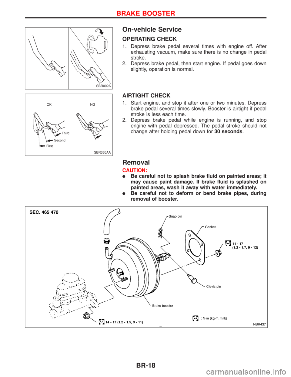
OPERATING CHECK
1. Depress brake pedal several times with engine off. After
exhausting vacuum, make sure there is no change in pedal
stroke.
2. Depress brake pedal, then start engine. If pedal goes down
slightly, operation is normal.
AIRTIGHT CHECK
1. Start engine, and stop it after one or two minutes. Depress
brake pedal several times slowly. Booster is airtight if pedal
stroke is less each time.
2. Depress brake pedal while engine is running, and stop
engine with pedal depressed. The pedal stroke should not
change after holding pedal down for30 seconds.
Removal
CAUTION:
lBe careful not to splash brake fluid on painted areas; it
may cause paint damage. If brake fluid is splashed on
painted areas, wash it away with water immediately.
lBe careful not to deform or bend brake pipes, during
removal of booster.
SBR002A
SBR365AA OK NG
Third
Second
First
NBR437
BRAKE BOOSTER
BR-18
Page 376 of 2267
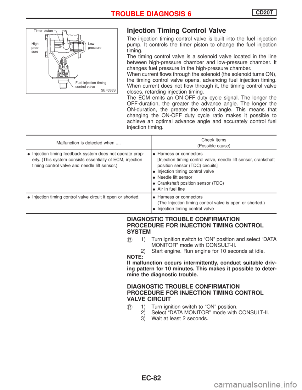
Injection Timing Control Valve
The injection timing control valve is built into the fuel injection
pump. It controls the timer piston to change the fuel injection
timing.
The timing control valve is a solenoid valve located in the line
between high-pressure chamber and low-pressure chamber. It
changes fuel pressure in the high-pressure chamber.
When current flows through the solenoid (the solenoid turns ON),
the timing control valve opens, advancing fuel injection timing.
When current does not flow through it, the timing control valve
closes, retarding injection timing.
The ECM emits an ON-OFF duty cycle signal. The longer the
OFF-duration, the greater the advance angle. The longer the
ON-duration, the greater the retard angle. This means that
changing the ON-OFF duty cycle ratio makes it possible to
achieve an optimal advance angle and accurately control fuel
injection timing.
Malfunction is detected when ....Check Items
(Possible cause)
lInjection timing feedback system does not operate prop-
erly. (This system consists essentially of ECM, injection
timing control valve and needle lift sensor.)lHarness or connectors
[Injection timing control valve, needle lift sensor, crankshaft
position sensor (TDC) circuits]
lInjection timing control valve
lNeedle lift sensor
lCrankshaft position sensor (TDC)
lAir in fuel line
lInjection timing control valve circuit it open or shorted.lHarness or connectors
(The Injection timing control valve is open or shorted.)
lInjection timing control valve
DIAGNOSTIC TROUBLE CONFIRMATION
PROCEDURE FOR INJECTION TIMING CONTROL
SYSTEM
1) Turn ignition switch to ªONº position and select ªDATA
MONITORº mode with CONSULT-II.
2) Start engine. Run engine for 10 seconds at idle.
NOTE:
If malfunction occurs intermittently, conduct suitable driv-
ing pattern for 10 minutes. This makes it possible to deter-
mine the diagnostic trouble.
DIAGNOSTIC TROUBLE CONFIRMATION
PROCEDURE FOR INJECTION TIMING CONTROL
VALVE CIRCUIT
1) Turn ignition switch to ªONº position.
2) Select ªDATA MONITORº mode with CONSULT-II.
3) Wait at least 2 seconds.
SEF638S Timer piston
High
pres-
sureLow
pressure
Fuel injection timing
control valve
TROUBLE DIAGNOSIS 6CD20T
EC-82
Page 418 of 2267
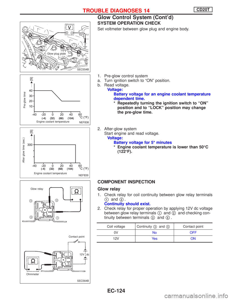
SYSTEM OPERATION CHECK
Set voltmeter between glow plug and engine body.
1. Pre-glow control system
a. Turn ignition switch to ªONº position.
b. Read voltage.
Voltage:
Battery voltage for an engine coolant temperature
dependent time.
* Repeatedly turning the ignition switch to ªONº
position and to ªLOCKº position may change
the pre-glow time.
2. After-glow system
Start engine and read voltage.
Voltage:
Battery voltage for 5* minutes
* Engine coolant temperature is lower than 50ÉC
(122ÉF).
COMPONENT INSPECTION
Glow relay
1. Check relay for coil continuity between glow relay terminals
p1andp2.
Continuity should exist.
2. Check relay for proper operation by applying 12V dc voltage
between glow relay terminals
p1andp2and checking con-
tinuity between terminals
p3andp5.
Coil voltage Continuityp3andp5Contact point
0VNo OFF
12VYe s O N
SEC554B Glow plug plate
NEF838
Pre-glow time
Engine coolant temperature
.(-4) (32) (68) (104)
NEF839 Engine coolant temperature
After glow time (sec.)
.(-4) (32) (68) (104)
SEC564B OhmmeterGlow relay
Contact point
12V dc
p2
p1
p3
p5
TROUBLE DIAGNOSES 14CD20T
Glow Control System (Cont'd)
EC-124
Page 464 of 2267
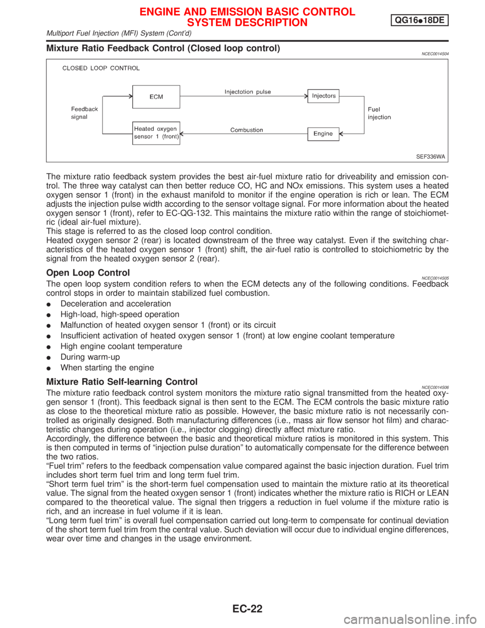
Mixture Ratio Feedback Control (Closed loop control)NCEC0014S04
The mixture ratio feedback system provides the best air-fuel mixture ratio for driveability and emission con-
trol. The three way catalyst can then better reduce CO, HC and NOx emissions. This system uses a heated
oxygen sensor 1 (front) in the exhaust manifold to monitor if the engine operation is rich or lean. The ECM
adjusts the injection pulse width according to the sensor voltage signal. For more information about the heated
oxygen sensor 1 (front), refer to EC-QG-132. This maintains the mixture ratio within the range of stoichiomet-
ric (ideal air-fuel mixture).
This stage is referred to as the closed loop control condition.
Heated oxygen sensor 2 (rear) is located downstream of the three way catalyst. Even if the switching char-
acteristics of the heated oxygen sensor 1 (front) shift, the air-fuel ratio is controlled to stoichiometric by the
signal from the heated oxygen sensor 2 (rear).
Open Loop ControlNCEC0014S05The open loop system condition refers to when the ECM detects any of the following conditions. Feedback
control stops in order to maintain stabilized fuel combustion.
IDeceleration and acceleration
IHigh-load, high-speed operation
IMalfunction of heated oxygen sensor 1 (front) or its circuit
IInsufficient activation of heated oxygen sensor 1 (front) at low engine coolant temperature
IHigh engine coolant temperature
IDuring warm-up
IWhen starting the engine
Mixture Ratio Self-learning ControlNCEC0014S06The mixture ratio feedback control system monitors the mixture ratio signal transmitted from the heated oxy-
gen sensor 1 (front). This feedback signal is then sent to the ECM. The ECM controls the basic mixture ratio
as close to the theoretical mixture ratio as possible. However, the basic mixture ratio is not necessarily con-
trolled as originally designed. Both manufacturing differences (i.e., mass air flow sensor hot film) and charac-
teristic changes during operation (i.e., injector clogging) directly affect mixture ratio.
Accordingly, the difference between the basic and theoretical mixture ratios is monitored in this system. This
is then computed in terms of ªinjection pulse durationº to automatically compensate for the difference between
the two ratios.
ªFuel trimº refers to the feedback compensation value compared against the basic injection duration. Fuel trim
includes short term fuel trim and long term fuel trim.
ªShort term fuel trimº is the short-term fuel compensation used to maintain the mixture ratio at its theoretical
value. The signal from the heated oxygen sensor 1 (front) indicates whether the mixture ratio is RICH or LEAN
compared to the theoretical value. The signal then triggers a reduction in fuel volume if the mixture ratio is
rich, and an increase in fuel volume if it is lean.
ªLong term fuel trimº is overall fuel compensation carried out long-term to compensate for continual deviation
of the short term fuel trim from the central value. Such deviation will occur due to individual engine differences,
wear over time and changes in the usage environment.
SEF336WA
ENGINE AND EMISSION BASIC CONTROL
SYSTEM DESCRIPTIONQG16I18DE
Multiport Fuel Injection (MFI) System (Cont'd)
EC-22
Page 480 of 2267
FREEZE FRAME DATA AND 1ST TRIP FREEZE FRAME DATANCEC0031S02The ECM records the driving conditions such as fuel system status, calculated load value, engine coolant
temperature, short term fuel trim, long term fuel trim, engine speed, vehicle speed and absolute pressure
sensor at the moment a malfunction is detected.
Data which are stored in the ECM memory, along with the 1st trip DTC, are called 1st trip freeze frame data.
The data, stored together with the DTC data, are called freeze frame data and displayed on CONSULT-II or
GST. The 1st trip freeze frame data can only be displayed on the CONSULT-II screen, not on the GST. For
details, see EC-QG-58.
Only one set of freeze frame data (either 1st trip freeze frame data or freeze frame data) can be stored in the
ECM. 1st trip freeze frame data is stored in the ECM memory along with the 1st trip DTC. There is no prior-
ity for 1st trip freeze frame data and it is updated each time a different 1st trip DTC is detected. However, once
freeze frame data (2nd trip detection/MI on) is stored in the ECM memory, 1st trip freeze frame data is no
longer stored. Remember, only one set of freeze frame data can be stored in the ECM. The ECM has the fol-
lowing priorities to update the data.
Priority Items
1Freeze frame data Misfire Ð DTC: P0300 - P0304 (0300 - 0304)
Fuel Injection System Function Ð DTC: P0171 (0171), P0172 (0172)
2 Except the above items
3 1st trip freeze frame data
For example, the EGR malfunction (Priority: 2) was detected and the freeze frame data was stored in the 2nd
trip. After that when the misfire (Priority: 1) is detected in another trip, the freeze frame data will be updated
from the EGR malfunction to the misfire. The 1st trip freeze frame data is updated each time a different mal-
function is detected. There is no priority for 1st trip freeze frame data. However, once freeze frame data is
stored in the ECM memory, 1st trip freeze data is no longer stored (because only one freeze frame data or
1st trip freeze frame data can be stored in the ECM). If freeze frame data is stored in the ECM memory and
freeze frame data with the same priority occurs later, the first (original) freeze frame data remains unchanged
in the ECM memory.
Both 1st trip freeze frame data and freeze frame data (along with the DTCs) are cleared when the ECM
memory is erased. Procedures for clearing the ECM memory are described in ªHOW TO ERASE EMISSION-
RELATED DIAGNOSTIC INFORMATIONº. Refer to EC-QG-44.
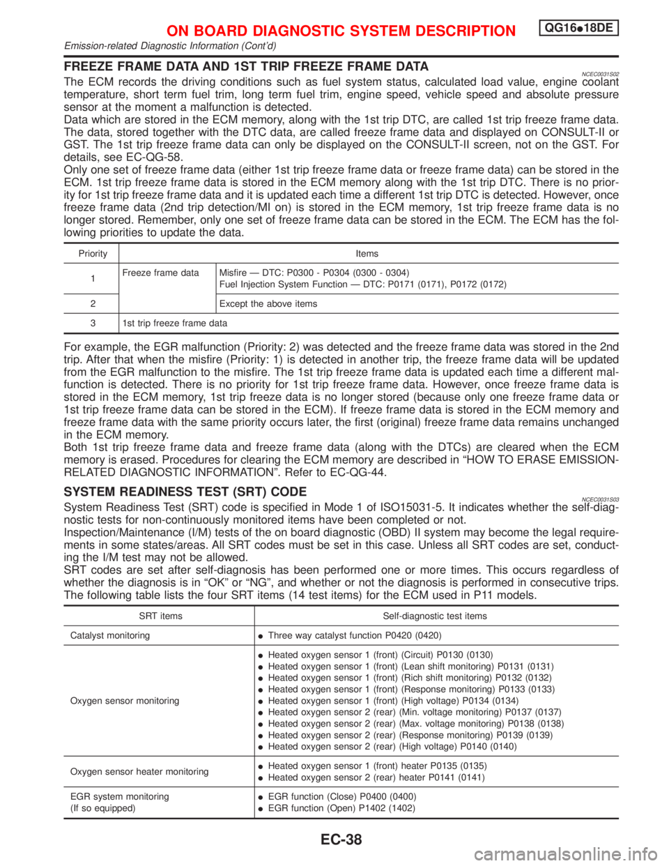
SYSTEM READINESS TEST (SRT) CODENCEC0031S03System Readiness Test (SRT) code is specified in Mode 1 of ISO15031-5. It indicates whether the self-diag-
nostic tests for non-continuously monitored items have been completed or not.
Inspection/Maintenance (I/M) tests of the on board diagnostic (OBD) II system may become the legal require-
ments in some states/areas. All SRT codes must be set in this case. Unless all SRT codes are set, conduct-
ing the I/M test may not be allowed.
SRT codes are set after self-diagnosis has been performed one or more times. This occurs regardless of
whether the diagnosis is in ªOKº or ªNGº, and whether or not the diagnosis is performed in consecutive trips.
The following table lists the four SRT items (14 test items) for the ECM used in P11 models.
SRT items Self-diagnostic test items
Catalyst monitoringIThree way catalyst function P0420 (0420)
Oxygen sensor monitoringIHeated oxygen sensor 1 (front) (Circuit) P0130 (0130)
IHeated oxygen sensor 1 (front) (Lean shift monitoring) P0131 (0131)
IHeated oxygen sensor 1 (front) (Rich shift monitoring) P0132 (0132)
IHeated oxygen sensor 1 (front) (Response monitoring) P0133 (0133)
IHeated oxygen sensor 1 (front) (High voltage) P0134 (0134)
IHeated oxygen sensor 2 (rear) (Min. voltage monitoring) P0137 (0137)
IHeated oxygen sensor 2 (rear) (Max. voltage monitoring) P0138 (0138)
IHeated oxygen sensor 2 (rear) (Response monitoring) P0139 (0139)
IHeated oxygen sensor 2 (rear) (High voltage) P0140 (0140)
Oxygen sensor heater monitoringIHeated oxygen sensor 1 (front) heater P0135 (0135)
IHeated oxygen sensor 2 (rear) heater P0141 (0141)
EGR system monitoring
(If so equipped)IEGR function (Close) P0400 (0400)
IEGR function (Open) P1402 (1402)
ON BOARD DIAGNOSTIC SYSTEM DESCRIPTIONQG16I18DE
Emission-related Diagnostic Information (Cont'd)
EC-38