1999 NISSAN PRIMERA brake sensor
[x] Cancel search: brake sensorPage 16 of 2267
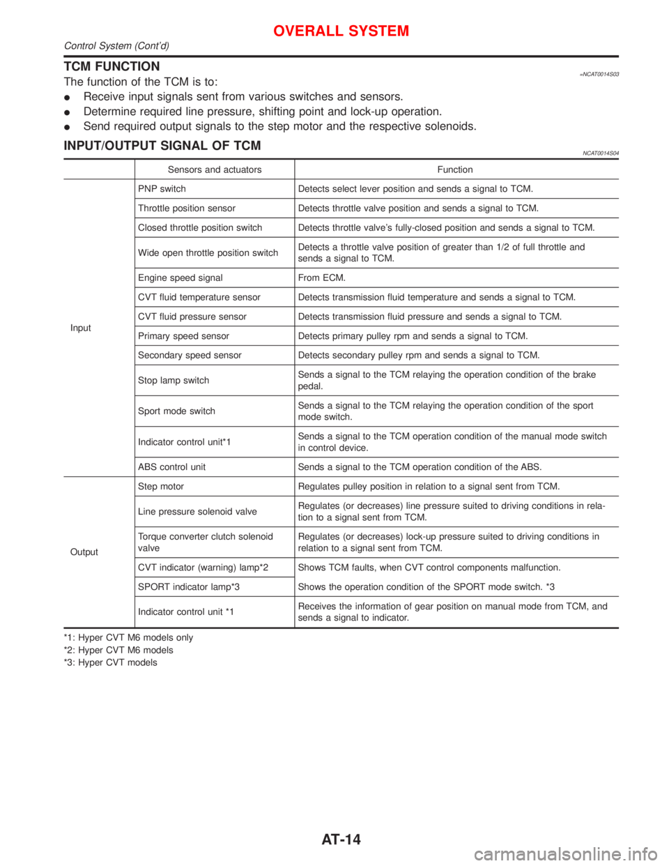
TCM FUNCTION=NCAT0014S03The function of the TCM is to:
IReceive input signals sent from various switches and sensors.
IDetermine required line pressure, shifting point and lock-up operation.
ISend required output signals to the step motor and the respective solenoids.
INPUT/OUTPUT SIGNAL OF TCMNCAT0014S04
Sensors and actuators Function
InputPNP switch Detects select lever position and sends a signal to TCM.
Throttle position sensor Detects throttle valve position and sends a signal to TCM.
Closed throttle position switch Detects throttle valve's fully-closed position and sends a signal to TCM.
Wide open throttle position switchDetects a throttle valve position of greater than 1/2 of full throttle and
sends a signal to TCM.
Engine speed signal From ECM.
CVT fluid temperature sensor Detects transmission fluid temperature and sends a signal to TCM.
CVT fluid pressure sensor Detects transmission fluid pressure and sends a signal to TCM.
Primary speed sensor Detects primary pulley rpm and sends a signal to TCM.
Secondary speed sensor Detects secondary pulley rpm and sends a signal to TCM.
Stop lamp switchSends a signal to the TCM relaying the operation condition of the brake
pedal.
Sport mode switchSends a signal to the TCM relaying the operation condition of the sport
mode switch.
Indicator control unit*1Sends a signal to the TCM operation condition of the manual mode switch
in control device.
ABS control unit Sends a signal to the TCM operation condition of the ABS.
OutputStep motor Regulates pulley position in relation to a signal sent from TCM.
Line pressure solenoid valveRegulates (or decreases) line pressure suited to driving conditions in rela-
tion to a signal sent from TCM.
Torque converter clutch solenoid
valveRegulates (or decreases) lock-up pressure suited to driving conditions in
relation to a signal sent from TCM.
CVT indicator (warning) lamp*2 Shows TCM faults, when CVT control components malfunction.
SPORT indicator lamp*3 Shows the operation condition of the SPORT mode switch. *3
Indicator control unit *1Receives the information of gear position on manual mode from TCM, and
sends a signal to indicator.
*1: Hyper CVT M6 models only
*2: Hyper CVT M6 models
*3: Hyper CVT models
OVERALL SYSTEM
Control System (Cont'd)
AT-14
Page 24 of 2267
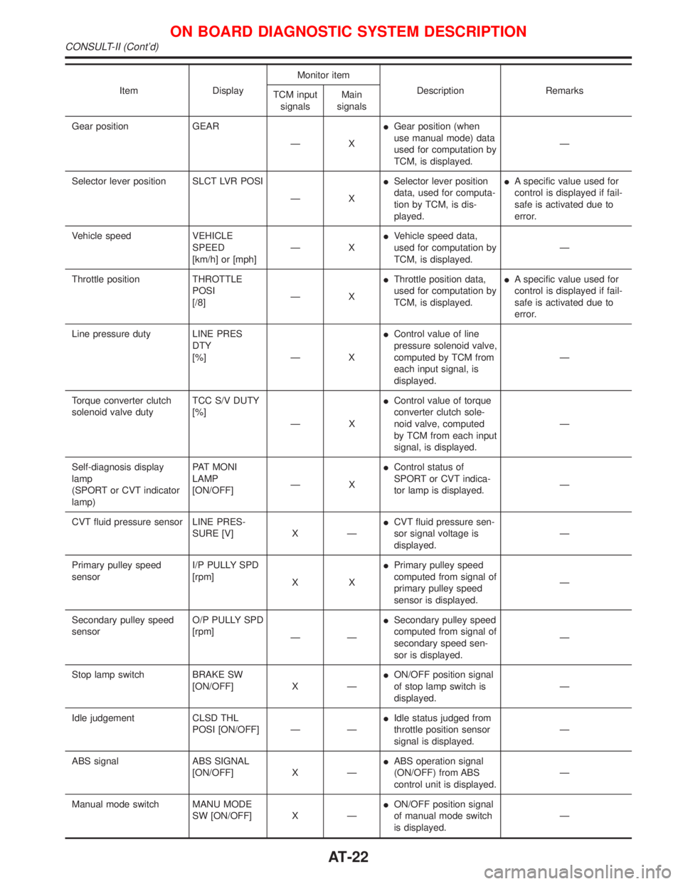
Item DisplayMonitor item
Description Remarks
TCM input
signalsMain
signals
Gear position GEAR
ÐXIGear position (when
use manual mode) data
used for computation by
TCM, is displayed.Ð
Selector lever position SLCT LVR POSI
ÐXISelector lever position
data, used for computa-
tion by TCM, is dis-
played.IA specific value used for
control is displayed if fail-
safe is activated due to
error.
Vehicle speed VEHICLE
SPEED
[km/h] or [mph]ÐXIVehicle speed data,
used for computation by
TCM, is displayed.Ð
Throttle position THROTTLE
POSI
[/8]ÐXIThrottle position data,
used for computation by
TCM, is displayed.IA specific value used for
control is displayed if fail-
safe is activated due to
error.
Line pressure duty LINE PRES
DTY
[%] Ð XIControl value of line
pressure solenoid valve,
computed by TCM from
each input signal, is
displayed.Ð
Torque converter clutch
solenoid valve dutyTCC S/V DUTY
[%]
ÐXIControl value of torque
converter clutch sole-
noid valve, computed
by TCM from each input
signal, is displayed.Ð
Self-diagnosis display
lamp
(SPORT or CVT indicator
lamp)PAT MONI
LAMP
[ON/OFF]ÐXIControl status of
SPORT or CVT indica-
tor lamp is displayed.Ð
CVT fluid pressure sensor LINE PRES-
SURE [V] X ÐICVT fluid pressure sen-
sor signal voltage is
displayed.Ð
Primary pulley speed
sensorI/P PULLY SPD
[rpm]
XXIPrimary pulley speed
computed from signal of
primary pulley speed
sensor is displayed.Ð
Secondary pulley speed
sensorO/P PULLY SPD
[rpm]
ÐÐISecondary pulley speed
computed from signal of
secondary speed sen-
sor is displayed.Ð
Stop lamp switch BRAKE SW
[ON/OFF] X ÐION/OFF position signal
of stop lamp switch is
displayed.Ð
Idle judgement CLSD THL
POSI [ON/OFF] Ð ÐIIdle status judged from
throttle position sensor
signal is displayed.Ð
ABS signal ABS SIGNAL
[ON/OFF] X ÐIABS operation signal
(ON/OFF) from ABS
control unit is displayed.Ð
Manual mode switch MANU MODE
SW [ON/OFF] X ÐION/OFF position signal
of manual mode switch
is displayed.Ð
ON BOARD DIAGNOSTIC SYSTEM DESCRIPTION
CONSULT-II (Cont'd)
AT-22
Page 33 of 2267
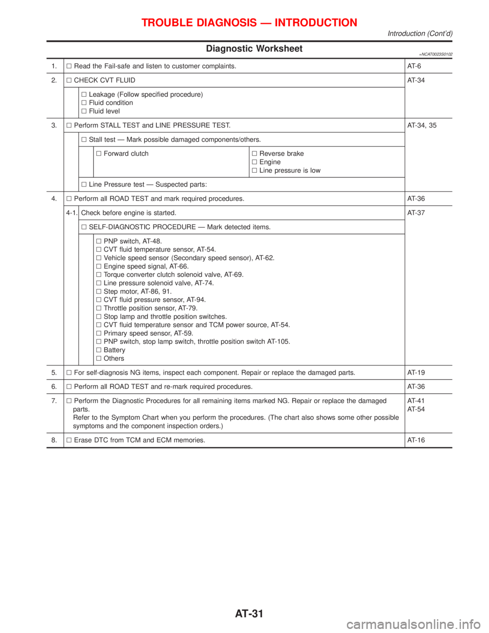
Diagnostic Worksheet=NCAT0023S0102
1.lRead the Fail-safe and listen to customer complaints. AT-6
2.lCHECK CVT FLUIDAT-34
lLeakage (Follow specified procedure)
lFluid condition
lFluid level
3.lPerform STALL TEST and LINE PRESSURE TEST. AT-34, 35
lStall test Ð Mark possible damaged components/others.
lForward clutchlReverse brake
lEngine
lLine pressure is low
lLine Pressure test Ð Suspected parts:
4.lPerform all ROAD TEST and mark required procedures. AT-36
4-1. Check before engine is started.AT-37
lSELF-DIAGNOSTIC PROCEDURE Ð Mark detected items.
lPNP switch, AT-48.
lCVT fluid temperature sensor, AT-54.
lVehicle speed sensor (Secondary speed sensor), AT-62.
lEngine speed signal, AT-66.
lTorque converter clutch solenoid valve, AT-69.
lLine pressure solenoid valve, AT-74.
lStep motor, AT-86, 91.
lCVT fluid pressure sensor, AT-94.
lThrottle position sensor, AT-79.
lStop lamp and throttle position switches.
lCVT fluid temperature sensor and TCM power source, AT-54.
lPrimary speed sensor, AT-59.
lPNP switch, stop lamp switch, throttle position switch AT-105.
lBattery
lOthers
5.lFor self-diagnosis NG items, inspect each component. Repair or replace the damaged parts. AT-19
6.lPerform all ROAD TEST and re-mark required procedures. AT-36
7.lPerform the Diagnostic Procedures for all remaining items marked NG. Repair or replace the damaged
parts.
Refer to the Symptom Chart when you perform the procedures. (The chart also shows some other possible
symptoms and the component inspection orders.)AT-41
AT-54
8.lErase DTC from TCM and ECM memories. AT-16
TROUBLE DIAGNOSIS Ð INTRODUCTION
Introduction (Cont'd)
AT-31
Page 46 of 2267
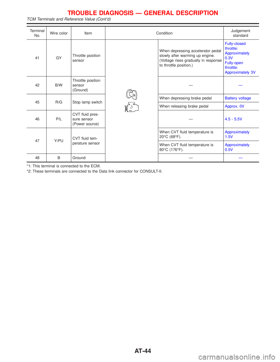
Terminal
No.Wire color Item ConditionJudgement
standard
41 GYThrottle position
sensor
When depressing accelerator pedal
slowly after warming up engine.
(Voltage rises gradually in response
to throttle position.)Fully-closed
throttle:
Approximately
0.3V
Fully-open
throttle:
Approximately 3V
42 B/WThrottle position
sensor
(Ground)ÐÐ
45 R/G Stop lamp switchWhen depressing brake pedalBattery voltage
When releasing brake pedalApprox. 0V
46 P/LCVT fluid pres-
sure sensor
(Power source)Ð4.5 - 5.5V
47 Y/PUCVT fluid tem-
perature sensorWhen CVT fluid temperature is
20ÉC (68ÉF).Approximately
1.5V
When CVT fluid temperature is
80ÉC (176ÉF).Approximately
0.5V
48 B Ground ÐÐ
*1: This terminal is connected to the ECM.
*2: These terminals are connected to the Data link connector for CONSULT-II.
TROUBLE DIAGNOSIS Ð GENERAL DESCRIPTION
TCM Terminals and Reference Value (Cont'd)
AT-44
Page 124 of 2267
Inspection................................................................. 36
Assembly ................................................................. 37
Installation ................................................................ 39
REAR DISC BRAKE TYPE 2...................................... 40
Component .............................................................. 40
Pad Replacement .................................................... 40
Removal ................................................................... 42
Disassembly............................................................. 42
Inspection................................................................. 42
Installation ................................................................ 43
REAR DRUM BRAKE................................................. 44
Components............................................................. 44
Removal ................................................................... 44
Inspection - Wheel Cylinder .................................... 45
Wheel Cylinder Overhaul......................................... 46
Inspection - Drum .................................................... 46
Inspection - Lining ................................................... 46
Installation ................................................................ 46
PARKING BRAKE CONTROL.................................... 48
Removal and Installation ......................................... 48
Inspection................................................................. 49
Adjustment ............................................................... 49
ANTI-LOCK BRAKE SYSTEM.................................... 50
Purpose.................................................................... 50
Operation ................................................................. 50
ABS Hydraulic Circuit .............................................. 50
System Components ............................................... 51
System Description .................................................. 51
Removal and Installation ......................................... 53
TROUBLE DIAGNOSES............................................. 57
How to Perform Trouble Diagnoses for Quick
and Accurate Repair ................................................ 57
Preliminary Check.................................................... 59
Component Parts and Harness Connector
Location ................................................................... 60
Circuit Diagram for Quick Pinpoint Check............... 61Wiring Diagram - ABS - ........................................... 62
Self-diagnosis (Only models with data link
connector terminal No. 8) ........................................ 67
TROUBLE DIAGNOSIS - GENERAL
DESCRIPTION............................................................. 69
CONSULT-II ............................................................. 69
CONSULT-II Inspection Procedure.......................... 70
Ground Circuit Check .............................................. 75
TROUBLE DIAGNOSIS - GENERAL
DESCRIPTION............................................................. 76
Malfunction Code/Symptom Chart........................... 76
TROUBLE DIAGNOSES FOR SELF-DIAGNOSTIC
ITEMS........................................................................... 77
Diagnostic Procedure 1 (Wheel sensor or rotor) .... 77
Diagnostic Procedure 2 (ABS actuator solenoid
valve and solenoid valve relay) ............................... 79
Diagnostic Procedure 3 (Motor Relay or motor) ..... 81
Diagnostic Procedure 4 (Low voltage) .................... 83
Diagnostic Procedure 5 (Control unit) ..................... 84
TROUBLE DIAGNOSES FOR SYMPTOMS............... 85
Diagnostic Procedure 6 (ABS works frequently) ..... 85
Diagnostic Procedure 7 (Unexpected pedal
action) ...................................................................... 86
Diagnostic Procedure 8 (Long stopping distance) .. 86
Diagnostic Procedure 9 (ABS does not work.) ....... 87
Diagnostic Procedure 10 (Pedal vibration and
noise) ....................................................................... 87
Diagnostic Procedure 11 (ABS Warning lamp
does not come on when ignition switch is turned
ON) .......................................................................... 88
Diagnostic Procedure 12 (Warning lamp stays on
when ignition switch is turned ON).......................... 90
SERVICE DATA AND SPECIFICATIONS (SDS)........ 91
General Specifications ............................................. 91
Inspection and Adjustment ...................................... 92
When you read wiring diagrams:
lRead GI section, ªHOW TO READ WIRING DIAGRAMSº.
lSee EL section, ªPOWER SUPPLY ROUTINGº for power distribution circuit.
lSee EL section for NATS information and wiring diagram.
When you perform trouble diagnoses, read GI section, ªHOW TO FOLLOW FLOW
CHART IN TROUBLE DIAGNOSESº and ªHOW TO PERFORM EFFICIENT DIAGNOSIS
FOR AN ELECTRICAL INCIDENTº.
BR-2
Page 125 of 2267
Supplemental Restraint System (SRS) ªAIR
BAGº and ªSEAT BELT PRE-TENSIONERº
The Supplemental Restraint System such as ªAIR BAGº and ªSEAT BELT PRE-TENSIONERº used along
with a seat belt, helps to reduce the risk or severity of injury to the driver and front passenger for certain
types of collision. The SRS system composition which is available to NISSAN MODEL P11 is as follows (The
composition varies according to the destination and optional equipment.):
lFor a frontal collision
The Supplemental Restraint System consists of driver air bag module (located in the center of the
steering wheel), front passenger air bag module (located on the instrument panel on passenger side),
front seat belt pre-tensioners, a diagnosis sensor unit, warning lamp, wiring harness and spiral cable.
lFor a side collision
The Supplemental Restraint System consists of front side air bag module (located in the outer side of
front seat), side air bag (satellite) sensor, diagnosis sensor unit (one of components of air bags for a
frontal collision), wiring harness, warning lamp (one of components of air bags for a frontal collision).
Information necessary to service the system safely is included in theRS sectionof this Service Manual.
WARNING:
lTo avoid rendering the SRS inoperative, which could increase the risk of personal injury or death
in the event of a collision which would result in air bag inflation, all maintenance should be per-
formed by an authorized NISSAN dealer.
lImproper maintenance, including incorrect removal and installation of the SRS, can lead to per-
sonal injury caused by unintentional activation of the system. For removal of Spiral Cable and
Air Bag Module, see the RS section.
lDo not use electrical test equipment on any circuit related to the SRS unless instructed to in this
Service Manual. Spiral cable and wiring harnesses covered with yellow insulation tape either just
before the harness connectors or for the complete harness are related to the SRS.
Precautions for Brake System
lRecommended fluid is brake fluid ªDOT 4º.
lNever reuse drained brake fluid.
lBe careful not to splash brake fluid on painted areas.
lTo clean or wash all parts of master cylinder, disc brake
caliper and wheel cylinder, use clean brake fluid.
lNever use mineral oils such as gasoline or kerosene.
They will ruin rubber parts of the hydraulic system.
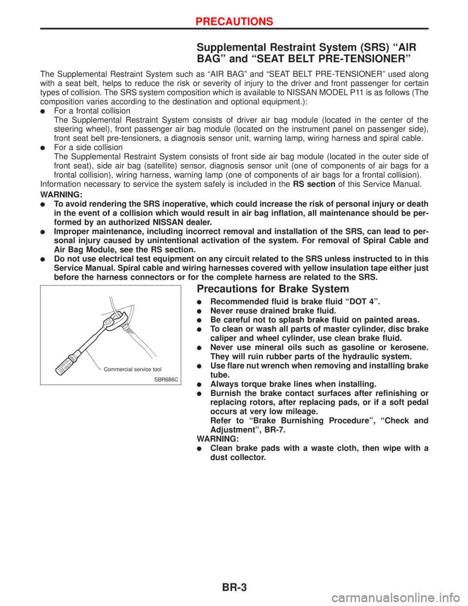
lUse flare nut wrench when removing and installing brake
tube.
lAlways torque brake lines when installing.
lBurnish the brake contact surfaces after refinishing or
replacing rotors, after replacing pads, or if a soft pedal
occurs at very low mileage.
Refer to ªBrake Burnishing Procedureº, ªCheck and
Adjustmentº, BR-7.
WARNING:
lClean brake pads with a waste cloth, then wipe with a
dust collector.
SBR686C Commercial service tool
PRECAUTIONS
BR-3
Page 173 of 2267
System Components
System Description
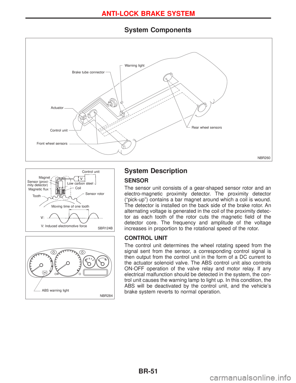
SENSOR
The sensor unit consists of a gear-shaped sensor rotor and an
electro-magnetic proximity detector. The proximity detector
(ªpick-upº) contains a bar magnet around which a coil is wound.
The detector is installed on the back side of the brake rotor. An
alternating voltage is generated in the coil of the proximity detec-
tor as each tooth of the rotor cuts the magnetic field of the
detector core. The frequency and amplitude of the voltage
increases in proportion to the rotational speed of the rotor.
CONTROL UNIT
The control unit determines the wheel rotating speed from the
signal sent from the sensor, a corresponding control signal is
then output from the control unit in the form of a DC current to
the actuator solenoid valve. The ABS control unit also controls
ON-OFF operation of the valve relay and motor relay. If any
electrical malfunction should be detected in the system, the con-
trol unit causes the warning lamp to light up. In this condition, the
ABS will be deactivated by the control unit, and the vehicle's
brake system reverts to normal operation.
NBR260 Warning light
Brake tube connector
Actuator
Front wheel sensorsControl unitRear wheel sensors
SBR124B Control unit
Magnet
.Sensor (proxi-
mity detector)
Magnetic flux
Tooth
V: Induced electromotive forceMoving time of one toothSensor rotor Coil Low carbon steel
NBR284 ABS warning light
ANTI-LOCK BRAKE SYSTEM
BR-51
Page 175 of 2267
Removal and Installation
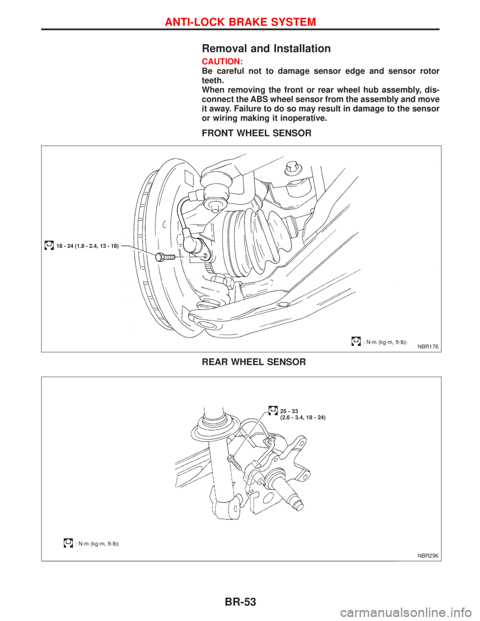
CAUTION:
Be careful not to damage sensor edge and sensor rotor
teeth.
When removing the front or rear wheel hub assembly, dis-
connect the ABS wheel sensor from the assembly and move
it away. Failure to do so may result in damage to the sensor
or wiring making it inoperative.
FRONT WHEEL SENSOR
REAR WHEEL SENSOR
NBR176
18 - 24 (1.8 - 2.4, 13 - 18)
: N´m (kg-m, ft-lb)
NBR296
: N´m (kg-m, ft-lb)
25-33
(2.6 - 3.4, 18 - 24)
ANTI-LOCK BRAKE SYSTEM
BR-53