1999 NISSAN PRIMERA lights
[x] Cancel search: lightsPage 329 of 2267
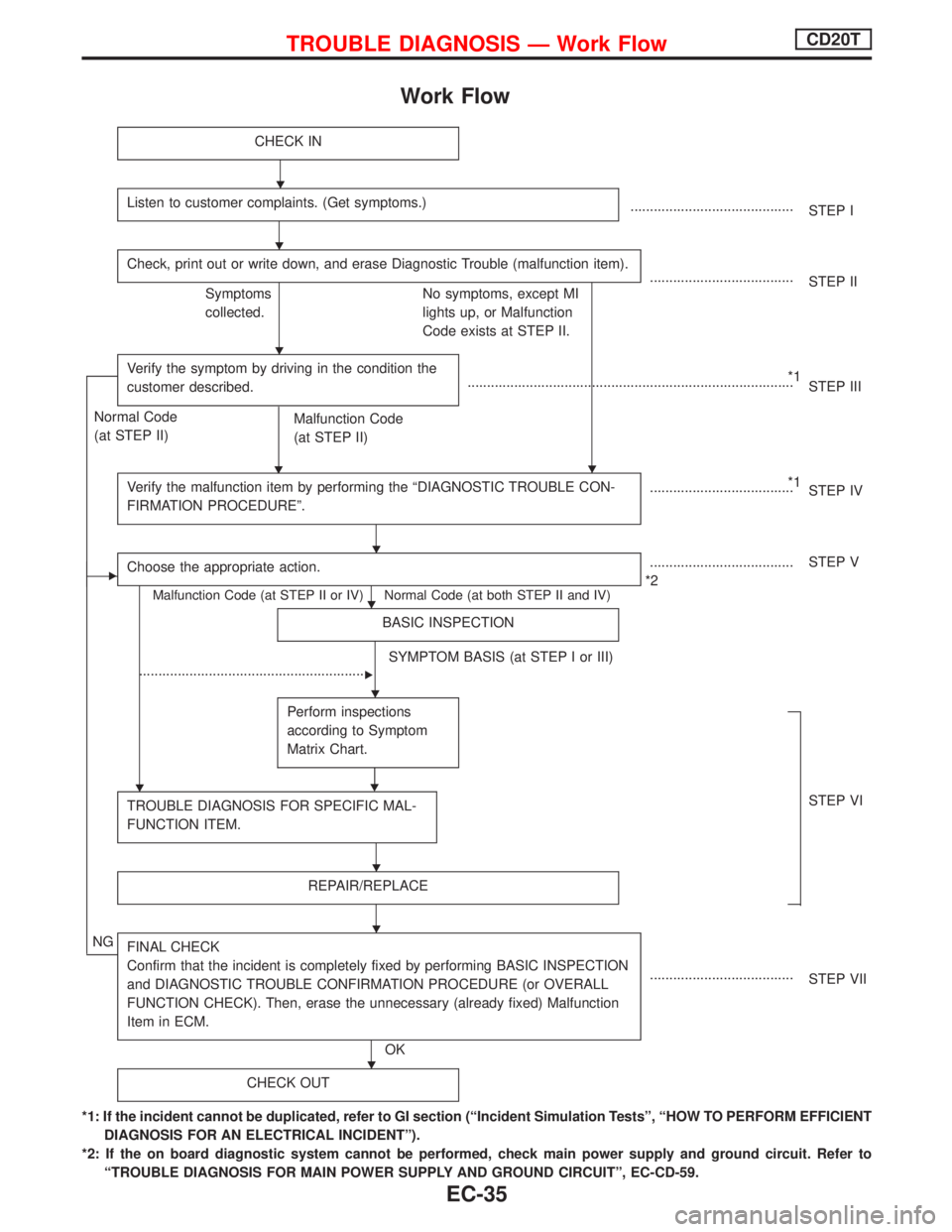
Work Flow
CHECK IN
Listen to customer complaints. (Get symptoms.)..........................................
STEP I
Check, print out or write down, and erase Diagnostic Trouble (malfunction item).
.....................................
STEP II
Symptoms
collected.No symptoms, except MI
lights up, or Malfunction
Code exists at STEP II.
Verify the symptom by driving in the condition the
customer described.
H
*1
....................................................................................
STEP III
Normal Code
(at STEP II)
Malfunction Code
(at STEP II)
Verify the malfunction item by performing the ªDIAGNOSTIC TROUBLE CON-
FIRMATION PROCEDUREº.
*1
.....................................
STEP IV
EChoose the appropriate action.
Malfunction Code (at STEP II or IV) Normal Code (at both STEP II and IV)
.....................................
*2STEP V
BASIC INSPECTION
SYMPTOM BASIS (at STEP I or III)
...........................................................
E
Perform inspections
according to Symptom
Matrix Chart.
H
TROUBLE DIAGNOSIS FOR SPECIFIC MAL-
FUNCTION ITEM.STEP VI
REPAIR/REPLACE
NGFINAL CHECK
Confirm that the incident is completely fixed by performing BASIC INSPECTION
and DIAGNOSTIC TROUBLE CONFIRMATION PROCEDURE (or OVERALL
FUNCTION CHECK). Then, erase the unnecessary (already fixed) Malfunction
Item in ECM.
OK.....................................
STEP VII
CHECK OUT
*1: If the incident cannot be duplicated, refer to GI section (ªIncident Simulation Testsº, ªHOW TO PERFORM EFFICIENT
DIAGNOSIS FOR AN ELECTRICAL INCIDENTº).
*2: If the on board diagnostic system cannot be performed, check main power supply and ground circuit. Refer to
ªTROUBLE DIAGNOSIS FOR MAIN POWER SUPPLY AND GROUND CIRCUITº, EC-CD-59.
H
H
H
H
H
H
H
H
H
H
H
TROUBLE DIAGNOSIS Ð Work FlowCD20T
EC-35
Page 478 of 2267
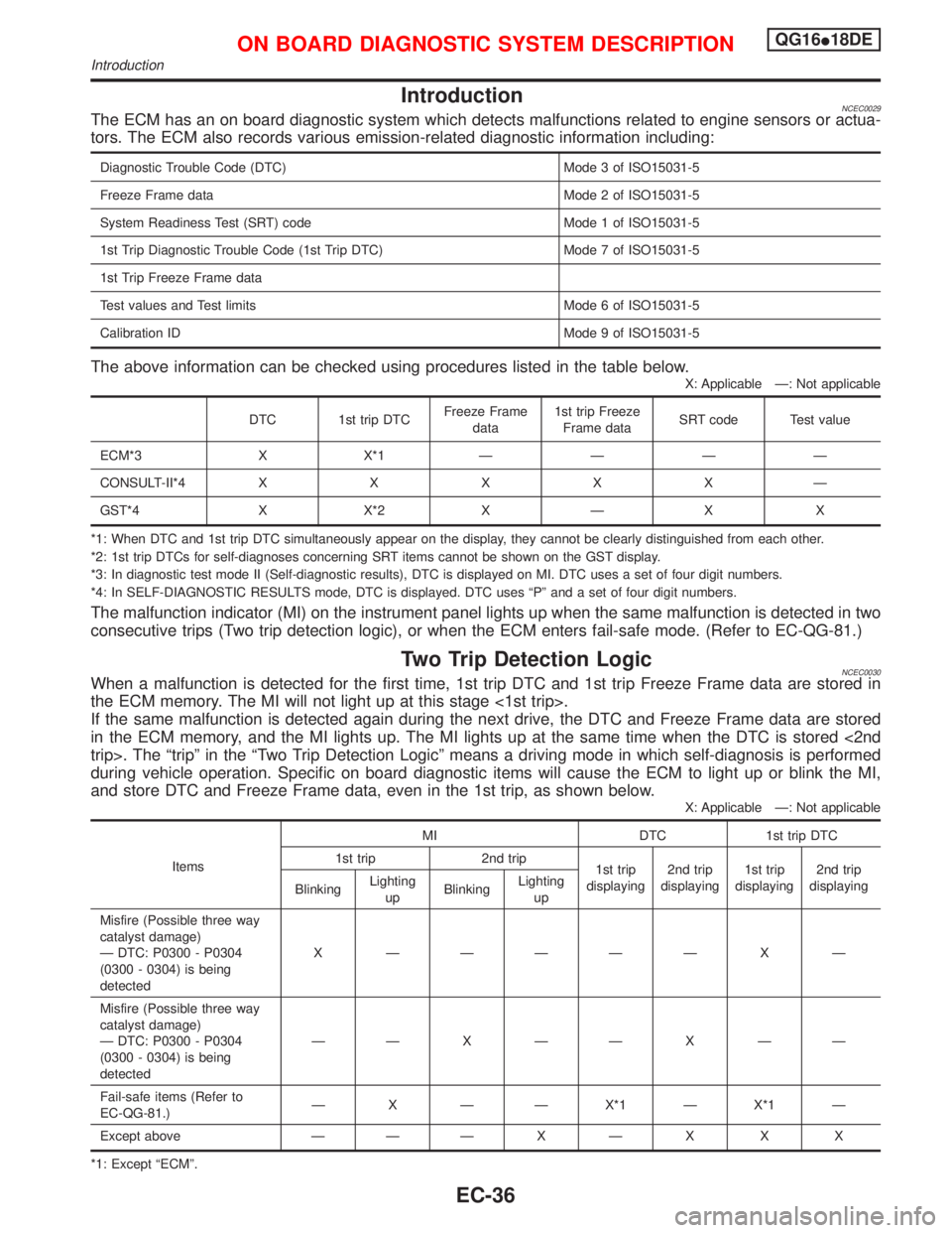
IntroductionNCEC0029The ECM has an on board diagnostic system which detects malfunctions related to engine sensors or actua-
tors. The ECM also records various emission-related diagnostic information including:
Diagnostic Trouble Code (DTC) Mode 3 of ISO15031-5
Freeze Frame data Mode 2 of ISO15031-5
System Readiness Test (SRT) code Mode 1 of ISO15031-5
1st Trip Diagnostic Trouble Code (1st Trip DTC) Mode 7 of ISO15031-5
1st Trip Freeze Frame data
Test values and Test limits Mode 6 of ISO15031-5
Calibration ID Mode 9 of ISO15031-5
The above information can be checked using procedures listed in the table below.
X: Applicable Ð: Not applicable
DTC 1st trip DTCFreeze Frame
data1st trip Freeze
Frame dataSRT code Test value
ECM*3 X X*1ÐÐÐÐ
CONSULT-II*4XXXXXÐ
GST*4 X X*2 X Ð X X
*1: When DTC and 1st trip DTC simultaneously appear on the display, they cannot be clearly distinguished from each other.
*2: 1st trip DTCs for self-diagnoses concerning SRT items cannot be shown on the GST display.
*3: In diagnostic test mode II (Self-diagnostic results), DTC is displayed on MI. DTC uses a set of four digit numbers.
*4: In SELF-DIAGNOSTIC RESULTS mode, DTC is displayed. DTC uses ªPº and a set of four digit numbers.
The malfunction indicator (MI) on the instrument panel lights up when the same malfunction is detected in two
consecutive trips (Two trip detection logic), or when the ECM enters fail-safe mode. (Refer to EC-QG-81.)
Two Trip Detection LogicNCEC0030When a malfunction is detected for the first time, 1st trip DTC and 1st trip Freeze Frame data are stored in
the ECM memory. The MI will not light up at this stage <1st trip>.
If the same malfunction is detected again during the next drive, the DTC and Freeze Frame data are stored
in the ECM memory, and the MI lights up. The MI lights up at the same time when the DTC is stored <2nd
trip>. The ªtripº in the ªTwo Trip Detection Logicº means a driving mode in which self-diagnosis is performed
during vehicle operation. Specific on board diagnostic items will cause the ECM to light up or blink the MI,
and store DTC and Freeze Frame data, even in the 1st trip, as shown below.
X: Applicable Ð: Not applicable
ItemsMI DTC 1st trip DTC
1st trip 2nd trip
1st trip
displaying2nd trip
displaying1st trip
displaying2nd trip
displaying
BlinkingLighting
upBlinkingLighting
up
Misfire (Possible three way
catalyst damage)
Ð DTC: P0300 - P0304
(0300 - 0304) is being
detectedX ÐÐÐÐÐ X Ð
Misfire (Possible three way
catalyst damage)
Ð DTC: P0300 - P0304
(0300 - 0304) is being
detectedÐÐXÐÐXÐÐ
Fail-safe items (Refer to
EC-QG-81.)Ð X Ð Ð X*1 Ð X*1 Ð
Except above Ð ÐÐXÐX X X
*1: Except ªECMº.
ON BOARD DIAGNOSTIC SYSTEM DESCRIPTIONQG16I18DE
Introduction
EC-36
Page 479 of 2267
Emission-related Diagnostic InformationNCEC0031DTC AND 1ST TRIP DTCNCEC0031S01The 1st trip DTC (whose number is the same as the DTC number) is displayed for the latest self-diagnostic
result obtained. If the ECM memory was cleared previously, and the 1st trip DTC did not reoccur, the 1st trip
DTC will not be displayed. If a malfunction is detected during the 1st trip, the 1st trip DTC is stored in the ECM
memory. The MI will not light up (two trip detection logic). If the same malfunction is not detected in the 2nd
trip (meeting the required driving pattern), the 1st trip DTC is cleared from the ECM memory. If the same mal-
function is detected in the 2nd trip, both the 1st trip DTC and DTC are stored in the ECM memory and the MI
lights up. In other words, the DTC is stored in the ECM memory and the MI lights up when the same malfunc-
tion occurs in two consecutive trips. If a 1st trip DTC is stored and a non-diagnostic operation is performed
between the 1st and 2nd trips, only the 1st trip DTC will continue to be stored. For malfunctions that blink or
light up the MI during the 1st trip, the DTC and 1st trip DTC are stored in the ECM memory.
Procedures for clearing the DTC and the 1st trip DTC from the ECM memory are described in ªHOW TO
ERASE EMISSION-RELATED DIAGNOSTIC INFORMATIONº. Refer to EC-QG-44.
For malfunctions in which 1st trip DTCs are displayed, refer to EC-QG-42. These items are required by legal
regulations to continuously monitor the system/component. In addition, the items monitored non-continuously
are also displayed on CONSULT-II.
1st trip DTC is specified in Mode 7 of ISO15031-5. 1st trip DTC detection occurs without lighting up the MI
and therefore does not warn the driver of a problem. However, 1st trip DTC detection will not prevent the
vehicle from being tested, for example during Inspection/Maintenance (I/M) tests.
When a 1st trip DTC is detected, check, print out or write down and erase (1st trip) DTC and Freeze Frame
data as specified in ªWork Flowº procedure Step II, refer to page EC-QG-70. Then perform ªDTC Confirma-
tion Procedureº or ªOverall Function Checkº to try to duplicate the problem. If the malfunction is duplicated,
the item requires repair.
How to read DTC and 1st Trip DTCNCEC0031S0101DTC and 1st trip DTC can be read by the following methods.
1)
No Tools
The number of blinks of MI in the Diagnostic Test Mode II (Self-Diagnostic Results) Examples: 0340, 1320,
0705, 0750, etc.
These DTCs are controlled by NISSAN.
2)
With CONSULT-II
With GST
CONSULT-II or GST (Generic Scan Tool) Examples: P0340, P1320, P0705, P0750, etc.
These DTCs are prescribed by ISO15031-6.
(CONSULT-II also displays the malfunctioning component or system.)
I1st trip DTC No. is the same as DTC No.
IOutput of a DTC indicates a malfunction. However, Mode II and GST do not indicate whether the
malfunction is still occurring or has occurred in the past and has returned to normal.
CONSULT-II can identify malfunction status as shown below. Therefore, using CONSULT-II (if avail-
able) is recommended.
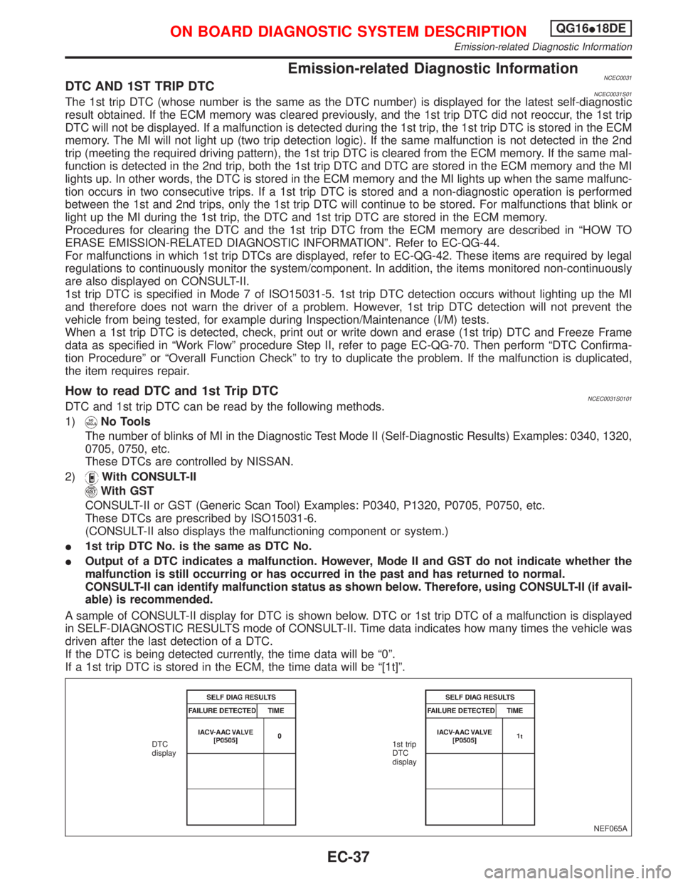
A sample of CONSULT-II display for DTC is shown below. DTC or 1st trip DTC of a malfunction is displayed
in SELF-DIAGNOSTIC RESULTS mode of CONSULT-II. Time data indicates how many times the vehicle was
driven after the last detection of a DTC.
If the DTC is being detected currently, the time data will be ª0º.
If a 1st trip DTC is stored in the ECM, the time data will be ª[1t]º.
NEF065A DTC
display1st trip
DTC
display
ON BOARD DIAGNOSTIC SYSTEM DESCRIPTIONQG16I18DE
Emission-related Diagnostic Information
EC-37
Page 487 of 2267
2. Select Mode 4 with GST (Generic Scan Tool).
The emission-related diagnostic information can be erased by selecting Mode 4 with GST (Generic Scan Tool).
How to Erase DTC (No Tools)NCEC0031S06031. If the ignition switch stays ªONº after repair work, be sure to turn ignition switch ªOFFº once. Wait at least
9 seconds and then turn it ªONº again.
2. Change the diagnostic test mode from Mode II to Mode I by using the data link connector. (See EC-QG-
48.)
The emission-related diagnostic information can be erased by changing the diagnostic test mode from Diag-
nostic Test Mode II to Mode I by using the data link connector. (Refer to EC-QG-48.)
NOTE:
IIf the battery is disconnected, the emission-related diagnostic information will be lost after approx.
24 hours.
IErasing the emission-related diagnostic information using CONSULT-II or GST is easier and
quicker than switching the mode using the data link connector.
IThe following data are cleared when the ECM memory is erased.
1) Diagnostic trouble codes
2) 1st trip diagnostic trouble codes
3) Freeze frame data
4) 1st trip freeze frame data
5) System readiness test (SRT) codes
6) Test values
7) Distance traveled while MI is activated
8) Others
Actual work procedures are explained using a DTC as an example. Be careful so that not only the DTC, but
all of the data listed above, are cleared from the ECM memory during work procedures.
Malfunction Indicator (MI)
NATS (Nissan Anti-Theft System)
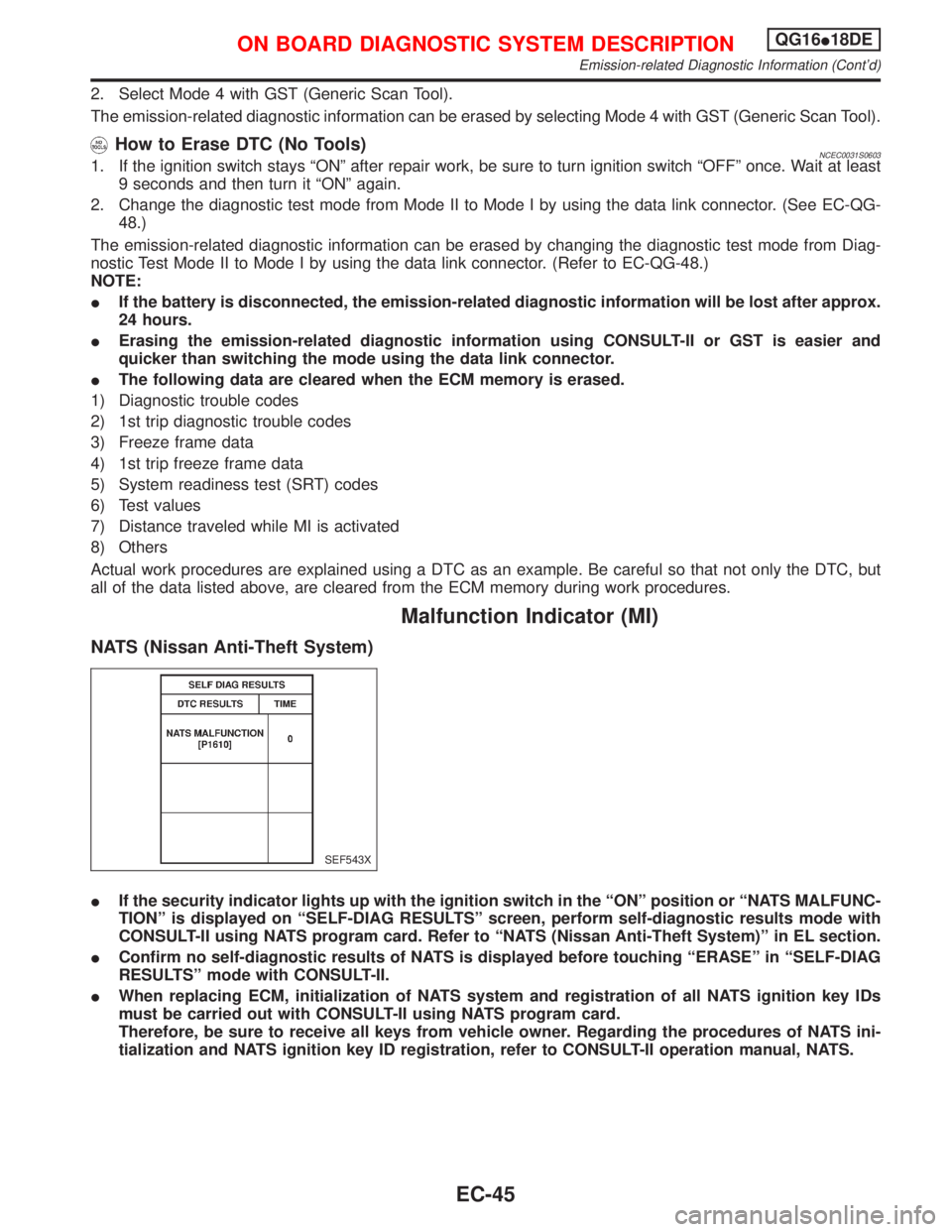
IIf the security indicator lights up with the ignition switch in the ªONº position or ªNATS MALFUNC-
TIONº is displayed on ªSELF-DIAG RESULTSº screen, perform self-diagnostic results mode with
CONSULT-II using NATS program card. Refer to ªNATS (Nissan Anti-Theft System)º in EL section.
IConfirm no self-diagnostic results of NATS is displayed before touching ªERASEº in ªSELF-DIAG
RESULTSº mode with CONSULT-II.
IWhen replacing ECM, initialization of NATS system and registration of all NATS ignition key IDs
must be carried out with CONSULT-II using NATS program card.
Therefore, be sure to receive all keys from vehicle owner. Regarding the procedures of NATS ini-
tialization and NATS ignition key ID registration, refer to CONSULT-II operation manual, NATS.
SEF543X
ON BOARD DIAGNOSTIC SYSTEM DESCRIPTIONQG16I18DE
Emission-related Diagnostic Information (Cont'd)
EC-45
Page 523 of 2267
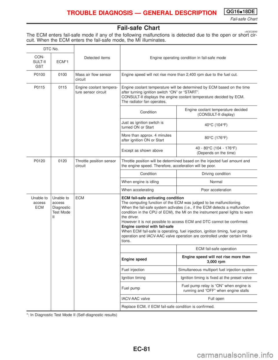
Fail-safe Chart=NCEC0040The ECM enters fail-safe mode if any of the following malfunctions is detected due to the open or short cir-
cuit. When the ECM enters the fail-safe mode, the MI illuminates.
DTC No.
Detected items Engine operating condition in fail-safe mode CON-
SULT-II
GSTECM*1
P0100 0100 Mass air flow sensor
circuitEngine speed will not rise more than 2,400 rpm due to the fuel cut.
P0115 0115 Engine coolant tempera-
ture sensor circuitEngine coolant temperature will be determined by ECM based on the time
after turning ignition switch ªONº or ªSTARTº.
CONSULT-II displays the engine coolant temperature decided by ECM.
The radiator fan operates.
ConditionEngine coolant temperature decided
(CONSULT-II display)
Just as ignition switch is
turned ON or Start40ÉC (104ÉF)
More than approx. 4 minutes
after ignition ON or Start80ÉC (176ÉF)
Except as shown above40 - 80ÉC (104 - 176ÉF)
(Depends on the time)
P0120 0120 Throttle position sensor
circuitThrottle position will be determined based on the injected fuel amount and
the engine speed. Therefore, acceleration will be poor.
Condition Driving condition
When engine is idling Normal
When accelerating Poor acceleration
Unable to
access
ECMUnable to
access
Diagnostic
Test Mode
IIECMECM fail-safe activating condition
The computing function of the ECM was judged to be malfunctioning.
When the fail-safe system activates (i.e., if the ECM detects a malfunction
condition in the CPU of ECM), the MI on the instrument panel lights to warn
the driver.
However it is not possible to access ECM and DTC cannot be confirmed.
Engine control with fail-safe
When ECM fail-safe is operating, fuel injection, ignition timing, fuel pump
operation and IACV-AAC valve operation are controlled under certain limita-
tions.
ECM fail-safe operation
Engine speedEngine speed will not rise more than
3,000 rpm
Fuel injection Simultaneous multiport fuel injection system
Ignition timing Ignition timing is fixed at the preset valve
Fuel pumpFuel pump relay is ªONº when engine is
running and ªOFFº when engine stalls
IACV-AAC valve Full open
Replace ECM, if ECM fail-safe condition is confirmed.
*: In Diagnostic Test Mode II (Self-diagnostic results)
TROUBLE DIAGNOSIS Ð GENERAL DESCRIPTIONQG16I18DE
Fail-safe Chart
EC-81
Page 552 of 2267
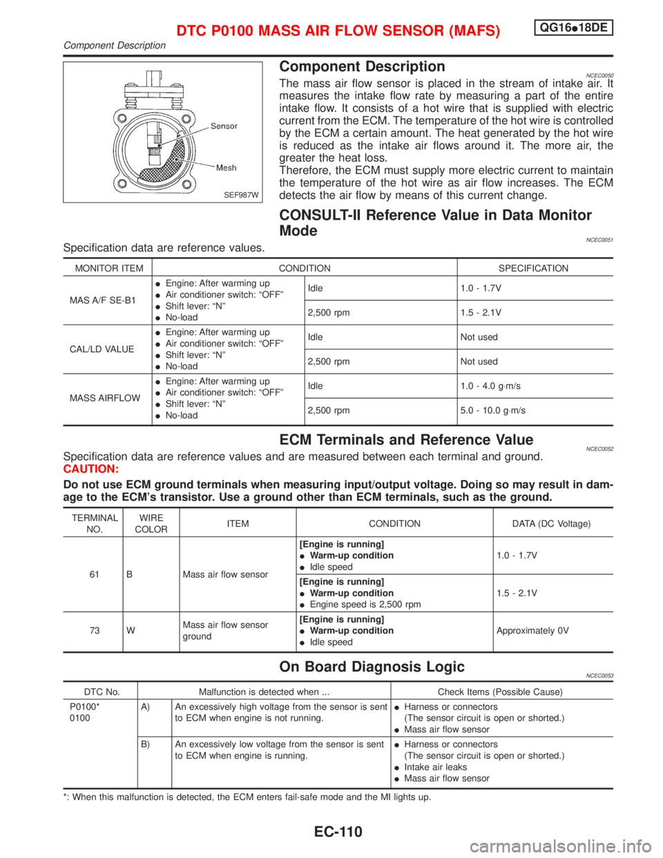
Component DescriptionNCEC0050The mass air flow sensor is placed in the stream of intake air. It
measures the intake flow rate by measuring a part of the entire
intake flow. It consists of a hot wire that is supplied with electric
current from the ECM. The temperature of the hot wire is controlled
by the ECM a certain amount. The heat generated by the hot wire
is reduced as the intake air flows around it. The more air, the
greater the heat loss.
Therefore, the ECM must supply more electric current to maintain
the temperature of the hot wire as air flow increases. The ECM
detects the air flow by means of this current change.
CONSULT-II Reference Value in Data Monitor
Mode
NCEC0051Specification data are reference values.
MONITOR ITEM CONDITION SPECIFICATION
MAS A/F SE-B1IEngine: After warming up
IAir conditioner switch: ªOFFº
IShift lever: ªNº
INo-loadIdle 1.0 - 1.7V
2,500 rpm 1.5 - 2.1V
CAL/LD VALUEIEngine: After warming up
IAir conditioner switch: ªOFFº
IShift lever: ªNº
INo-loadIdle Not used
2,500 rpm Not used
MASS AIRFLOWIEngine: After warming up
IAir conditioner switch: ªOFFº
IShift lever: ªNº
INo-loadIdle 1.0 - 4.0 g×m/s
2,500 rpm 5.0 - 10.0 g×m/s
ECM Terminals and Reference ValueNCEC0052Specification data are reference values and are measured between each terminal and ground.
CAUTION:
Do not use ECM ground terminals when measuring input/output voltage. Doing so may result in dam-
age to the ECM's transistor. Use a ground other than ECM terminals, such as the ground.
TERMINAL
NO.WIRE
COLORITEM CONDITION DATA (DC Voltage)
61 B Mass air flow sensor[Engine is running]
IWarm-up condition
IIdle speed1.0 - 1.7V
[Engine is running]
IWarm-up condition
IEngine speed is 2,500 rpm1.5 - 2.1V
73 WMass air flow sensor
ground[Engine is running]
IWarm-up condition
IIdle speedApproximately 0V
On Board Diagnosis LogicNCEC0053
DTC No. Malfunction is detected when ... Check Items (Possible Cause)
P0100*
0100A) An excessively high voltage from the sensor is sent
to ECM when engine is not running.IHarness or connectors
(The sensor circuit is open or shorted.)
IMass air flow sensor
B) An excessively low voltage from the sensor is sent
to ECM when engine is running.IHarness or connectors
(The sensor circuit is open or shorted.)
IIntake air leaks
IMass air flow sensor
*: When this malfunction is detected, the ECM enters fail-safe mode and the MI lights up.
SEF987W
DTC P0100 MASS AIR FLOW SENSOR (MAFS)QG16I18DE
Component Description
EC-110
Page 562 of 2267
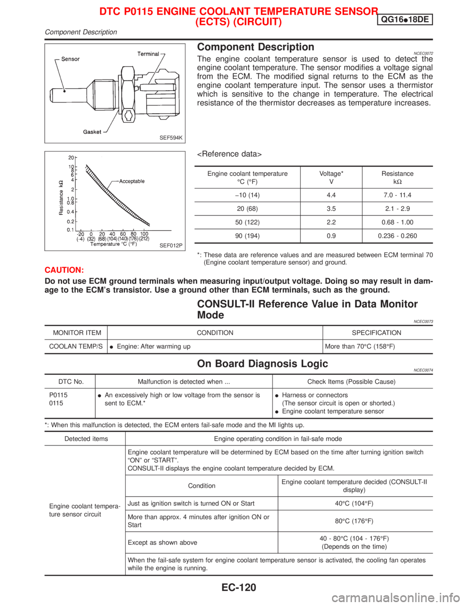
Component DescriptionNCEC0072The engine coolant temperature sensor is used to detect the
engine coolant temperature. The sensor modifies a voltage signal
from the ECM. The modified signal returns to the ECM as the
engine coolant temperature input. The sensor uses a thermistor
which is sensitive to the change in temperature. The electrical
resistance of the thermistor decreases as temperature increases.
Engine coolant temperature
ÉC (ÉF)Voltage*
VResistance
kW
þ10 (14) 4.4 7.0 - 11.4
20 (68) 3.5 2.1 - 2.9
50 (122) 2.2 0.68 - 1.00
90 (194) 0.9 0.236 - 0.260
*: These data are reference values and are measured between ECM terminal 70
(Engine coolant temperature sensor) and ground.
CAUTION:
Do not use ECM ground terminals when measuring input/output voltage. Doing so may result in dam-
age to the ECM's transistor. Use a ground other than ECM terminals, such as the ground.
CONSULT-II Reference Value in Data Monitor
Mode
NCEC0073
MONITOR ITEM CONDITION SPECIFICATION
COOLAN TEMP/SIEngine: After warming up More than 70ÉC (158ÉF)
On Board Diagnosis LogicNCEC0074
DTC No. Malfunction is detected when ... Check Items (Possible Cause)
P0115
0115IAn excessively high or low voltage from the sensor is
sent to ECM.*IHarness or connectors
(The sensor circuit is open or shorted.)
IEngine coolant temperature sensor
*: When this malfunction is detected, the ECM enters fail-safe mode and the MI lights up.
Detected items Engine operating condition in fail-safe mode
Engine coolant tempera-
ture sensor circuitEngine coolant temperature will be determined by ECM based on the time after turning ignition switch
ªONº or ªSTARTº.
CONSULT-II displays the engine coolant temperature decided by ECM.
ConditionEngine coolant temperature decided (CONSULT-II
display)
Just as ignition switch is turned ON or Start 40ÉC (104ÉF)
More than approx. 4 minutes after ignition ON or
Start80ÉC (176ÉF)
Except as shown above40 - 80ÉC (104 - 176ÉF)
(Depends on the time)
When the fail-safe system for engine coolant temperature sensor is activated, the cooling fan operates
while the engine is running.
SEF594K
SEF012P
DTC P0115 ENGINE COOLANT TEMPERATURE SENSOR
(ECTS) (CIRCUIT)QG16I18DE
Component Description
EC-120
Page 568 of 2267
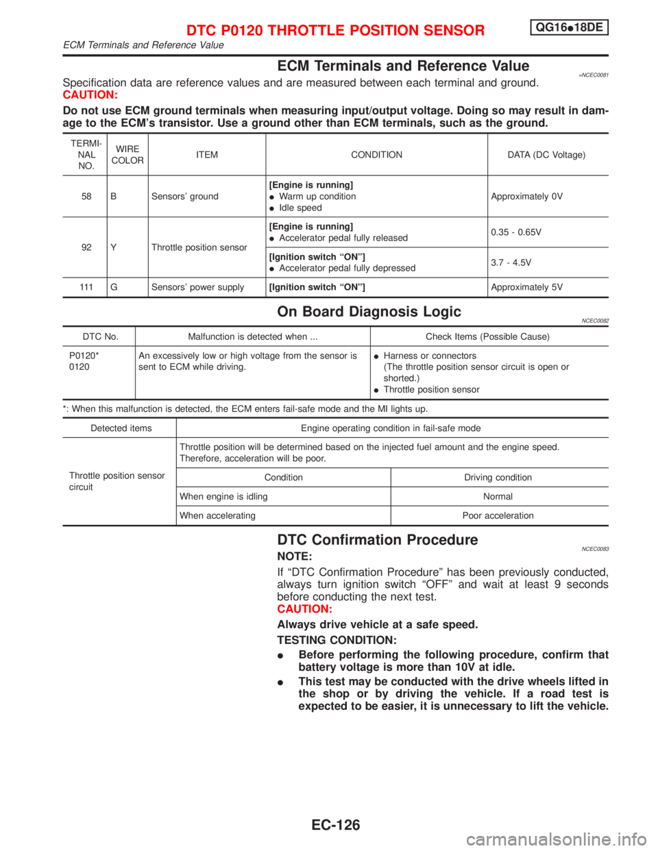
ECM Terminals and Reference Value=NCEC0081Specification data are reference values and are measured between each terminal and ground.
CAUTION:
Do not use ECM ground terminals when measuring input/output voltage. Doing so may result in dam-
age to the ECM's transistor. Use a ground other than ECM terminals, such as the ground.
TERMI-
NAL
NO.WIRE
COLORITEM CONDITION DATA (DC Voltage)
58 B Sensors' ground[Engine is running]
IWarm up condition
IIdle speedApproximately 0V
92 Y Throttle position sensor[Engine is running]
IAccelerator pedal fully released0.35 - 0.65V
[Ignition switch ªONº]
IAccelerator pedal fully depressed3.7 - 4.5V
111 G Sensors' power supply[Ignition switch ªONº]Approximately 5V
On Board Diagnosis LogicNCEC0082
DTC No. Malfunction is detected when ... Check Items (Possible Cause)
P0120*
0120An excessively low or high voltage from the sensor is
sent to ECM while driving.IHarness or connectors
(The throttle position sensor circuit is open or
shorted.)
IThrottle position sensor
*: When this malfunction is detected, the ECM enters fail-safe mode and the MI lights up.
Detected items Engine operating condition in fail-safe mode
Throttle position sensor
circuitThrottle position will be determined based on the injected fuel amount and the engine speed.
Therefore, acceleration will be poor.
Condition Driving condition
When engine is idling Normal
When accelerating Poor acceleration
DTC Confirmation ProcedureNCEC0083NOTE:
If ªDTC Confirmation Procedureº has been previously conducted,
always turn ignition switch ªOFFº and wait at least 9 seconds
before conducting the next test.
CAUTION:
Always drive vehicle at a safe speed.
TESTING CONDITION:
IBefore performing the following procedure, confirm that
battery voltage is more than 10V at idle.
IThis test may be conducted with the drive wheels lifted in
the shop or by driving the vehicle. If a road test is
expected to be easier, it is unnecessary to lift the vehicle.
DTC P0120 THROTTLE POSITION SENSORQG16I18DE
ECM Terminals and Reference Value
EC-126