1999 NISSAN PRIMERA oil temperature
[x] Cancel search: oil temperaturePage 36 of 2267
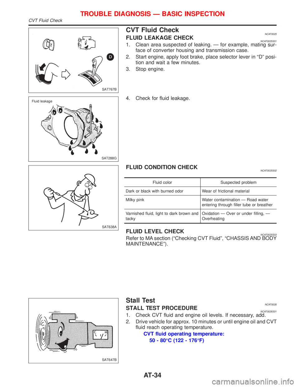
CVT Fluid CheckNCAT0025FLUID LEAKAGE CHECKNCAT0025S011. Clean area suspected of leaking. Ð for example, mating sur-
face of converter housing and transmission case.
2. Start engine, apply foot brake, place selector lever in ªDº posi-
tion and wait a few minutes.
3. Stop engine.
4. Check for fluid leakage.
FLUID CONDITION CHECKNCAT0025S02
Fluid color Suspected problem
Dark or black with burned odor Wear of frictional material
Milky pink Water contamination Ð Road water
entering through filler tube or breather
Varnished fluid, light to dark brown and
tackyOxidation Ð Over or under filling, Ð
Overheating
FLUID LEVEL CHECKNCAT0025S03Refer to MA section (ªChecking CVT Fluidº, ªCHASSIS AND BODY
MAINTENANCEº).
Stall TestNCAT0026STALL TEST PROCEDURENCAT0026S011. Check CVT fluid and engine oil levels. If necessary, add.
2. Drive vehicle for approx. 10 minutes or until engine oil and CVT
fluid reach operating temperature.
CVT fluid operating temperature:
50 - 80ÉC (122 - 176ÉF)
SAT767B
SAT288G Fluid leakage
SAT638A
SAT647B
TROUBLE DIAGNOSIS Ð BASIC INSPECTION
CVT Fluid Check
AT-34
Page 37 of 2267
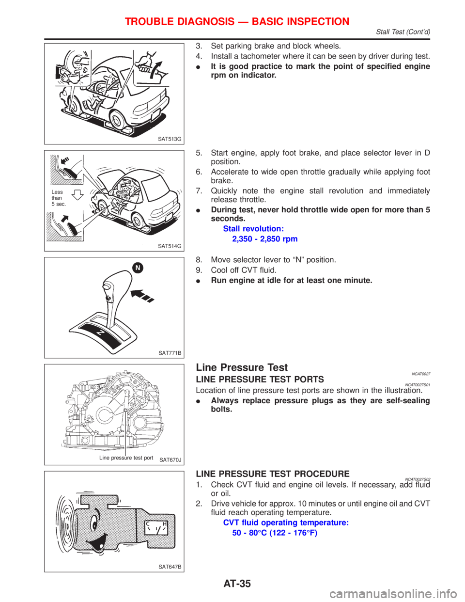
3. Set parking brake and block wheels.
4. Install a tachometer where it can be seen by driver during test.
IIt is good practice to mark the point of specified engine
rpm on indicator.
5. Start engine, apply foot brake, and place selector lever in D
position.
6. Accelerate to wide open throttle gradually while applying foot
brake.
7. Quickly note the engine stall revolution and immediately
release throttle.
IDuring test, never hold throttle wide open for more than 5
seconds.
Stall revolution:
2,350 - 2,850 rpm
8. Move selector lever to ªNº position.
9. Cool off CVT fluid.
IRun engine at idle for at least one minute.
Line Pressure TestNCAT0027LINE PRESSURE TEST PORTSNCAT0027S01Location of line pressure test ports are shown in the illustration.
IAlways replace pressure plugs as they are self-sealing
bolts.
LINE PRESSURE TEST PROCEDURENCAT0027S021. Check CVT fluid and engine oil levels. If necessary, add fluid
or oil.
2. Drive vehicle for approx. 10 minutes or until engine oil and CVT
fluid reach operating temperature.
CVT fluid operating temperature:
50 - 80ÉC (122 - 176ÉF)
SAT513G
SAT514G Less
than
5 sec.
SAT771B
SAT670J Line pressure test port
SAT647B
TROUBLE DIAGNOSIS Ð BASIC INSPECTION
Stall Test (Cont'd)
AT-35
Page 341 of 2267
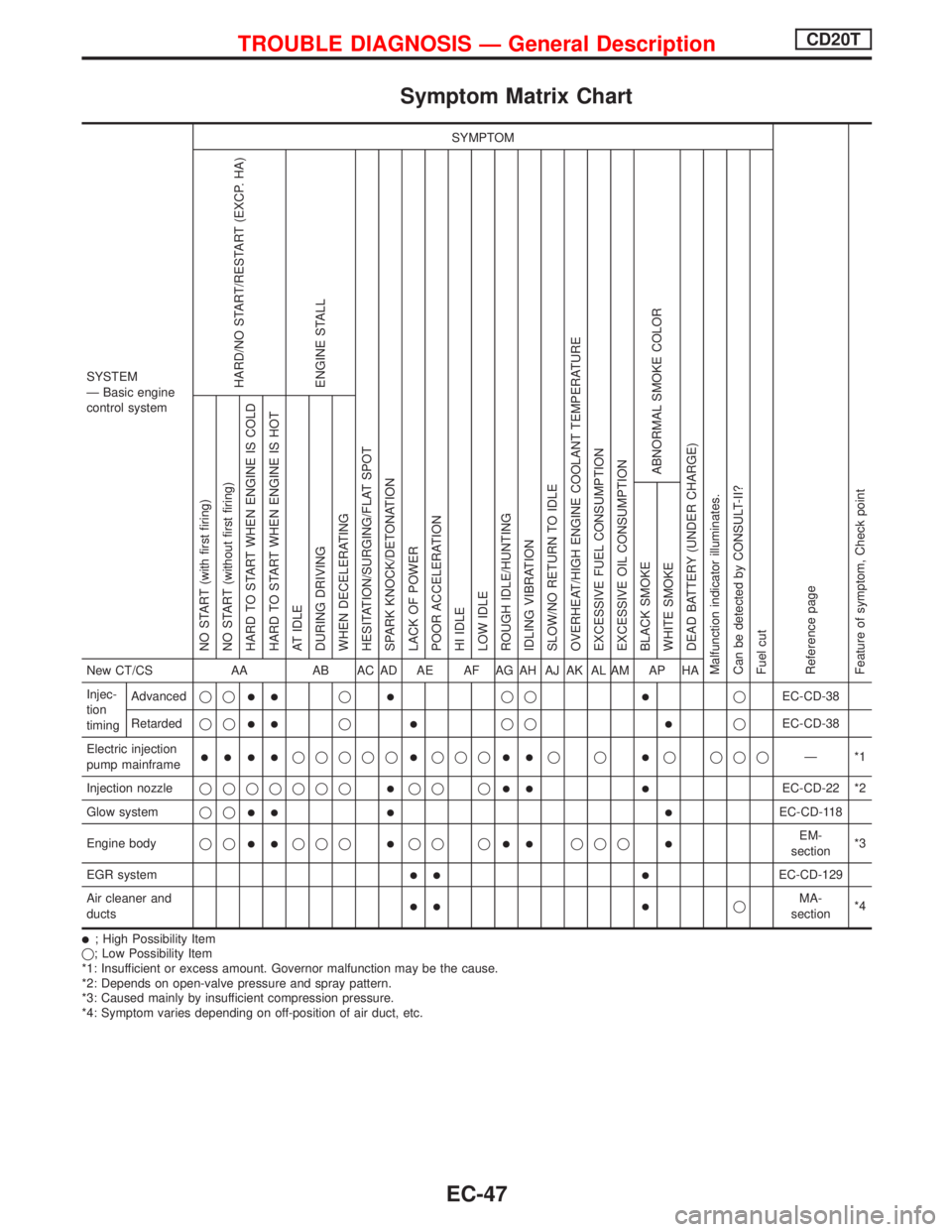
Symptom Matrix Chart
SYSTEM
Ð Basic engine
control systemSYMPTOM
Reference page
Feature of symptom, Check pointHARD/NO START/RESTART (EXCP. HA)
ENGINE STALL
HESITATION/SURGING/FLAT SPOT
SPARK KNOCK/DETONATION
LACK OF POWER
POOR ACCELERATION
HI IDLE
LOW IDLE
ROUGH IDLE/HUNTING
IDLING VIBRATION
SLOW/NO RETURN TO IDLE
OVERHEAT/HIGH ENGINE COOLANT TEMPERATURE
EXCESSIVE FUEL CONSUMPTION
EXCESSIVE OIL CONSUMPTION
ABNORMAL SMOKE COLOR
DEAD BATTERY (UNDER CHARGE)
Malfunction indicator illuminates.
Can be detected by CONSULT-II?
Fuel cutNO START (with first firing)
NO START (without first firing)
HARD TO START WHEN ENGINE IS COLD
HARD TO START WHEN ENGINE IS HOT
AT IDLE
DURING DRIVING
WHEN DECELERATING
BLACK SMOKE
WHITE SMOKENew CT/CS AA AB AC AD AE AF AG AH AJ AK AL AM AP HA
Injec-
tion
timingAdvancedqq
llqlqqlqEC-CD-38
Retardedqq
llqlqqlqEC-CD-38
Electric injection
pump mainframe
llllqqqqqlqqqllqqlq qqqÐ*1
Injection nozzleqqqqqqq
lqq qll lEC-CD-22 *2
Glow systemqq
ll l lEC-CD-118
Engine bodyqq
llqqqlqq qllqqqlEM-
section*3
EGR system
ll lEC-CD-129
Air cleaner and
ducts
ll lqMA-
section*4
l; High Possibility Item
q; Low Possibility Item
*1: Insufficient or excess amount. Governor malfunction may be the cause.
*2: Depends on open-valve pressure and spray pattern.
*3: Caused mainly by insufficient compression pressure.
*4: Symptom varies depending on off-position of air duct, etc.
TROUBLE DIAGNOSIS Ð General DescriptionCD20T
EC-47
Page 342 of 2267
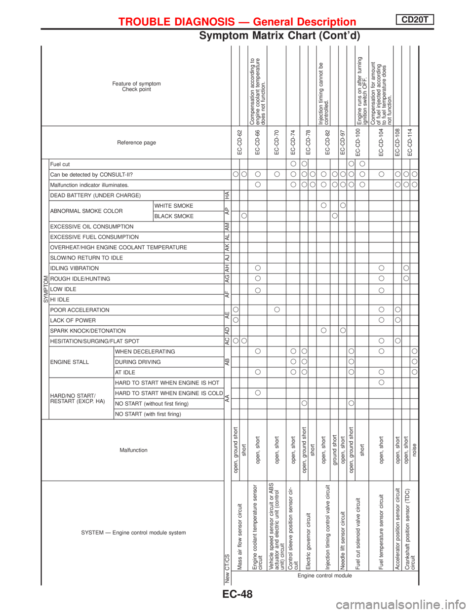
SYSTEM Ð Engine control module systemMalfunction
SYMPTOM
Reference page Feature of symptom
Check point
HARD/NO START/
RESTART (EXCP. HA) ENGINE STALL HESITATION/SURGING/FLAT SPOT SPARK KNOCK/DETONATION
LACK OF POWER
POOR ACCELERATION
HI IDLE
LOW IDLE
ROUGH IDLE/HUNTING
IDLING VIBRATION
SLOW/NO RETURN TO IDLE
OVERHEAT/HIGH ENGINE COOLANT TEMPERATURE
EXCESSIVE FUEL CONSUMPTION
EXCESSIVE OIL CONSUMPTION ABNORMAL SMOKE COLOR
DEAD BATTERY (UNDER CHARGE) Malfunction indicator illuminates.
Can be detected by CONSULT-II?
Fuel cut
NO START (with first firing) NO START (without first firing)
HARD TO START WHEN ENGINE IS COLD
HARD TO START WHEN ENGINE IS HOT
AT IDLE
DURING DRIVING
WHEN DECELERATINGBLACK SMOKE WHITE SMOKE
New CT/CS AA AB AC AD AE AF AG AH AJ AK AL AM AP HAEngine control moduleMass air flow sensor circuitopen, ground shortqqq q
EC-CD-62
shortqqq
Engine coolant temperature sensor
circuitopen, shortqqq qqq qqEC-CD-66Compensation according to
engine coolant temperature
does not function.
Vehicle speed sensor circuit or ABS
actuator and electric unit (control
unit) circuitopen, shortqqEC-CD-70
Control sleeve position sensor cir-
cuitopen, shortqqq qqqEC-CD-74
Electric governor circuitopen, ground shortq qqq qqq
EC-CD-78
shortqq
Injection timing control valve circuitopen, shortqqqq
EC-CD-82Injection timing cannot be
controlled.
ground shortqqq
Needle lift sensor circuit open, shortqqqqEC-CD-97
Fuel cut solenoid valve circuitopen, ground shortq qqq qqq
EC-CD-100
shortqqqEngine runs on after turning
ignition switch OFF.
Fuel temperature sensor circuit open, shortqq qq qq q qq qEC-CD-104Compensation for amount
of fuel injected according
to fuel temperature does
not function.
Accelerator position sensor circuit open, shortqqq qqEC-CD-108
Crankshaft position sensor (TDC)
circuitopen, shortqq qq
EC-CD-114
noiseqqq qq
TROUBLE DIAGNOSIS Ð General DescriptionCD20T
Symptom Matrix Chart (Cont'd)
EC-48
Page 343 of 2267
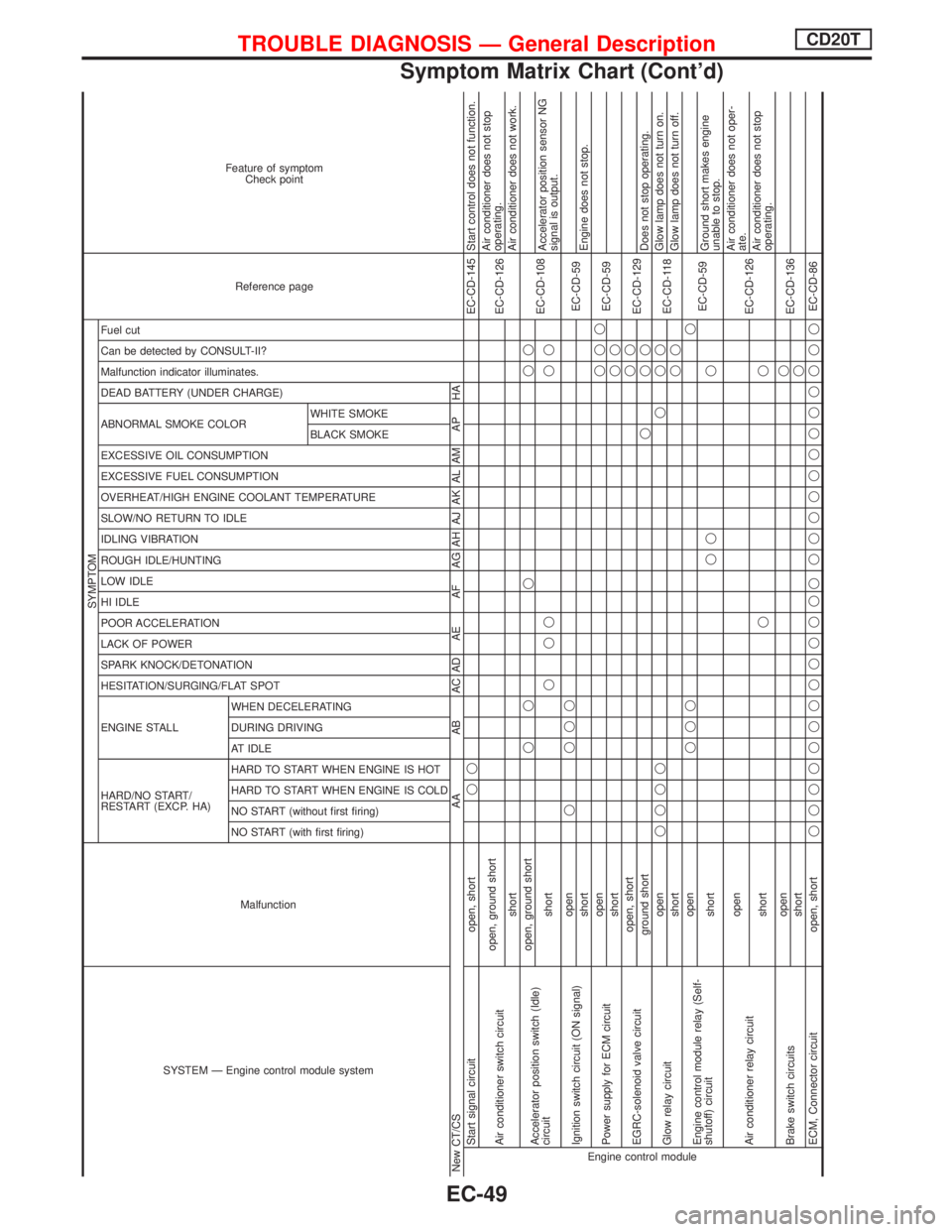
SYSTEM Ð Engine control module systemMalfunction
SYMPTOM
Reference page Feature of symptom
Check point
HARD/NO START/
RESTART (EXCP. HA) ENGINE STALL HESITATION/SURGING/FLAT SPOT SPARK KNOCK/DETONATION
LACK OF POWER
POOR ACCELERATION
HI IDLE
LOW IDLE
ROUGH IDLE/HUNTING
IDLING VIBRATION
SLOW/NO RETURN TO IDLE
OVERHEAT/HIGH ENGINE COOLANT TEMPERATURE
EXCESSIVE FUEL CONSUMPTION
EXCESSIVE OIL CONSUMPTION ABNORMAL SMOKE COLOR
DEAD BATTERY (UNDER CHARGE) Malfunction indicator illuminates.
Can be detected by CONSULT-II?
Fuel cut
NO START (with first firing) NO START (without first firing)
HARD TO START WHEN ENGINE IS COLD
HARD TO START WHEN ENGINE IS HOT
AT IDLE
DURING DRIVING
WHEN DECELERATINGBLACK SMOKE WHITE SMOKE
New CT/CS AA AB AC AD AE AF AG AH AJ AK AL AM AP HAEngine control moduleStart signal circuit open, shortqqEC-CD-145 Start control does not function.
Air conditioner switch circuitopen, ground short
EC-CD-126Air conditioner does not stop
operating.
shortAir conditioner does not work.
Accelerator position switch (Idle)
circuitopen, ground shortqq q qq
EC-CD-108
shortqqq qqAccelerator position sensor NG
signal is output.
Ignition switch circuit (ON signal)openq qqq
EC-CD-59
shortEngine does not stop.
Power supply for ECM circuitopenqqq
EC-CD-59
shortqq
EGRC-solenoid valve circuitopen, shortqq
EC-CD-129
ground shortqqqDoes not stop operating.
Glow relay circuitopenqqqq q qq
EC-CD-118Glow lamp does not turn on.
shortqqGlow lamp does not turn off.
Engine control module relay (Self-
shutoff) circuitopenqqqq
EC-CD-59
shortqq qGround short makes engine
unable to stop.
Air conditioner relay circuitopen
EC-CD-126Air conditioner does not oper-
ate.
shortqqAir conditioner does not stop
operating.
Brake switch circuitsopenq
EC-CD-136
shortq
ECM, Connector circuit open, shortqqqqqqqqqqqqq qqqqqqqqqqqqEC-CD-86
TROUBLE DIAGNOSIS Ð General DescriptionCD20T
Symptom Matrix Chart (Cont'd)
EC-49
Page 381 of 2267
Cooling Fan (Overheat)
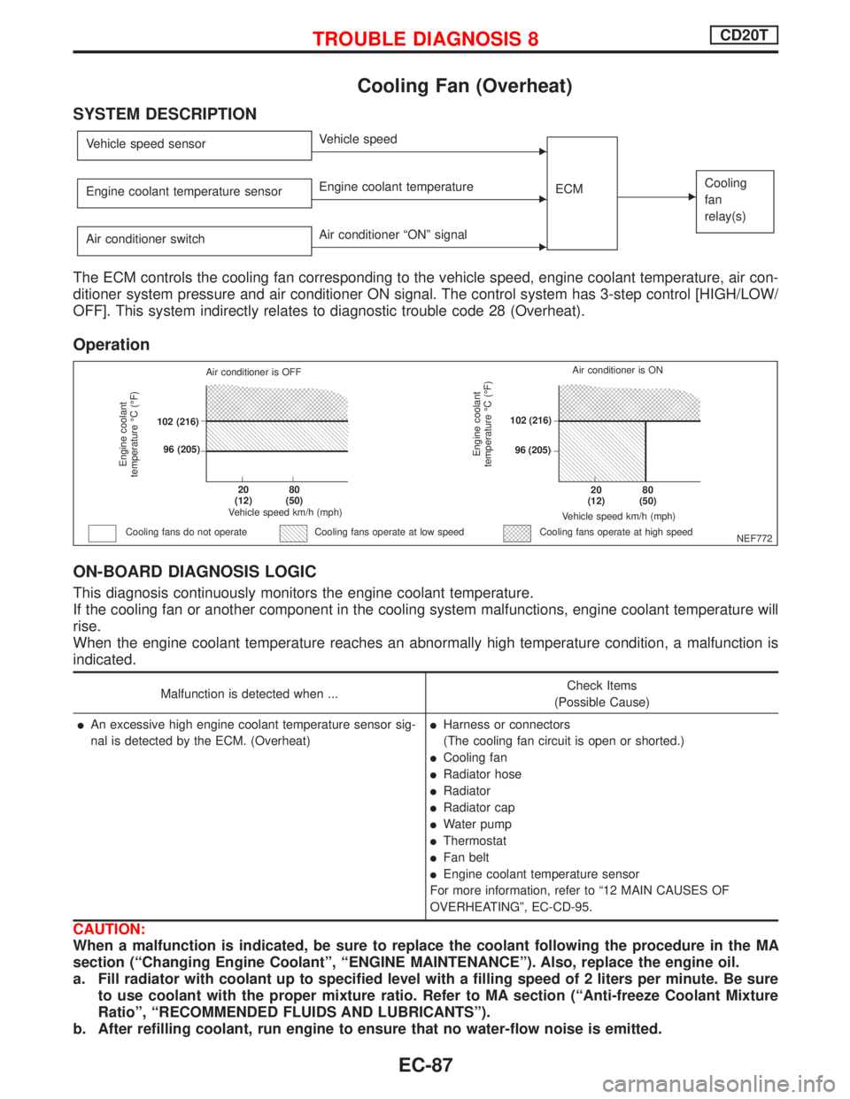
SYSTEM DESCRIPTION
Vehicle speed sensorEVehicle speed
ECM
ECooling
fan
relay(s)Engine coolant temperature sensorEEngine coolant temperature
Air conditioner switch
EAir conditioner ªONº signal
The ECM controls the cooling fan corresponding to the vehicle speed, engine coolant temperature, air con-
ditioner system pressure and air conditioner ON signal. The control system has 3-step control [HIGH/LOW/
OFF]. This system indirectly relates to diagnostic trouble code 28 (Overheat).
Operation
ON-BOARD DIAGNOSIS LOGIC
This diagnosis continuously monitors the engine coolant temperature.
If the cooling fan or another component in the cooling system malfunctions, engine coolant temperature will
rise.
When the engine coolant temperature reaches an abnormally high temperature condition, a malfunction is
indicated.
Malfunction is detected when ...Check Items
(Possible Cause)
lAn excessive high engine coolant temperature sensor sig-
nal is detected by the ECM. (Overheat)lHarness or connectors
(The cooling fan circuit is open or shorted.)
lCooling fan
lRadiator hose
lRadiator
lRadiator cap
lWater pump
lThermostat
lFan belt
lEngine coolant temperature sensor
For more information, refer to ª12 MAIN CAUSES OF
OVERHEATINGº, EC-CD-95.
CAUTION:
When a malfunction is indicated, be sure to replace the coolant following the procedure in the MA
section (ªChanging Engine Coolantº, ªENGINE MAINTENANCEº). Also, replace the engine oil.
a. Fill radiator with coolant up to specified level with a filling speed of 2 liters per minute. Be sure
to use coolant with the proper mixture ratio. Refer to MA section (ªAnti-freeze Coolant Mixture
Ratioº, ªRECOMMENDED FLUIDS AND LUBRICANTSº).
b. After refilling coolant, run engine to ensure that no water-flow noise is emitted.
NEF772
Engine coolant
temperature ÉC (ÉF)
Air conditioner is OFF
.102 (216)
.96 (205)
.20
(12).80
(50)
Vehicle speed km/h (mph)
Cooling fans do not operateCooling fans operate at high speed
Engine coolant
temperature ÉC (ÉF)
Vehicle speed km/h (mph)
.20
(12).80
(50)
.102 (216)
.96 (205)Air conditioner is ON
Cooling fans operate at low speed
TROUBLE DIAGNOSIS 8CD20T
EC-87
Page 388 of 2267
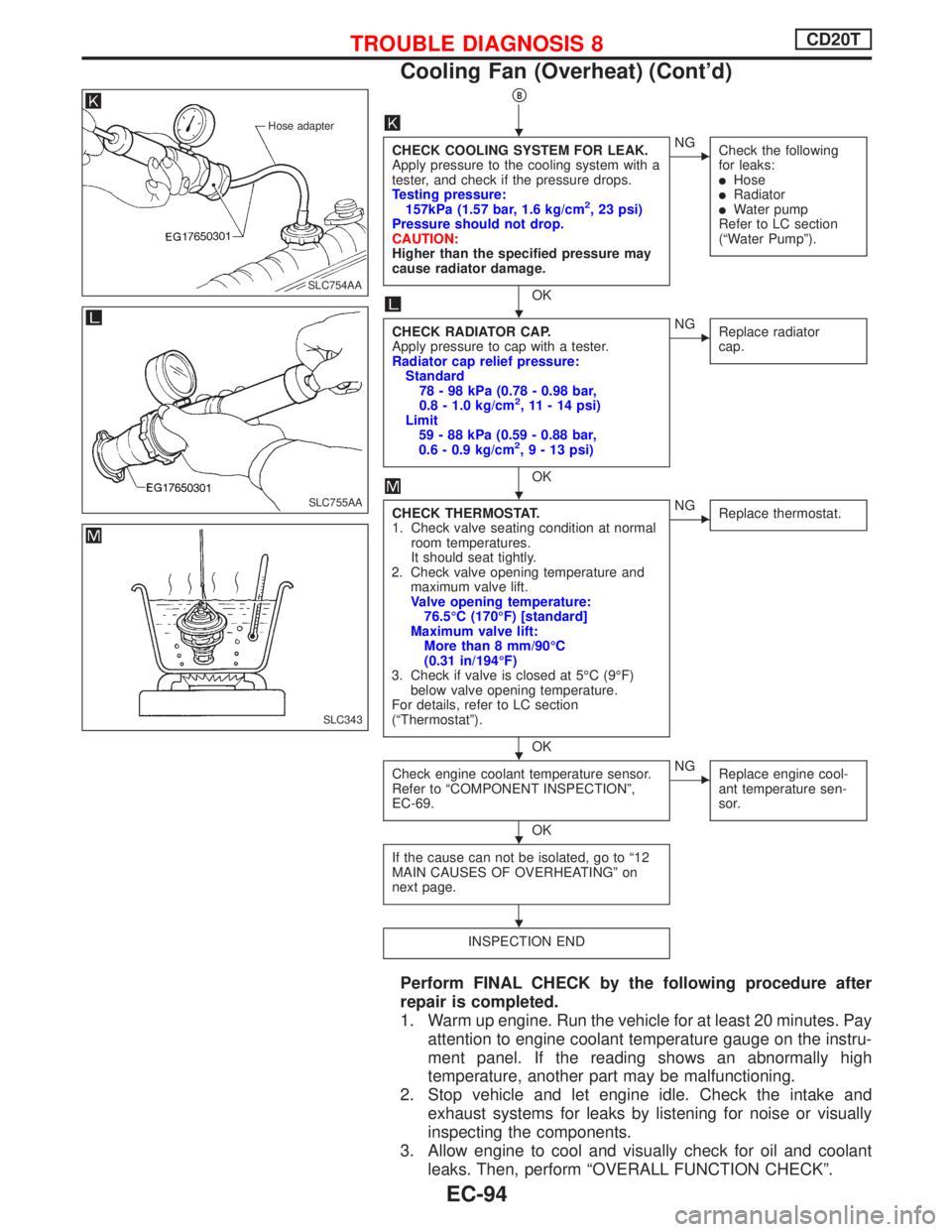
pB
CHECK COOLING SYSTEM FOR LEAK.
Apply pressure to the cooling system with a
tester, and check if the pressure drops.
Testing pressure:
157kPa (1.57 bar, 1.6 kg/cm
2, 23 psi)
Pressure should not drop.
CAUTION:
Higher than the specified pressure may
cause radiator damage.
OK
ENG
Check the following
for leaks:
lHoselRadiatorlWater pump
Refer to LC section
(ªWater Pumpº).
CHECK RADIATOR CAP.
Apply pressure to cap with a tester.
Radiator cap relief pressure:
Standard
78 - 98 kPa (0.78 - 0.98 bar,
0.8 - 1.0 kg/cm
2, 11 - 14 psi)
Limit
59 - 88 kPa (0.59 - 0.88 bar,
0.6 - 0.9 kg/cm
2,9-13psi)
OK
ENG
Replace radiator
cap.
CHECK THERMOSTAT.
1. Check valve seating condition at normal
room temperatures.
It should seat tightly.
2. Check valve opening temperature and
maximum valve lift.
Valve opening temperature:
76.5ÉC (170ÉF) [standard]
Maximum valve lift:
More than 8 mm/90ÉC
(0.31 in/194ÉF)
3. Check if valve is closed at 5ÉC (9ÉF)
below valve opening temperature.
For details, refer to LC section
(ªThermostatº).
OK
ENG
Replace thermostat.
Check engine coolant temperature sensor.
Refer to ªCOMPONENT INSPECTIONº,
EC-69.
OK
ENG
Replace engine cool-
ant temperature sen-
sor.
If the cause can not be isolated, go to ª12
MAIN CAUSES OF OVERHEATINGº on
next page.
INSPECTION END
Perform FINAL CHECK by the following procedure after
repair is completed.
1. Warm up engine. Run the vehicle for at least 20 minutes. Pay
attention to engine coolant temperature gauge on the instru-
ment panel. If the reading shows an abnormally high
temperature, another part may be malfunctioning.
2. Stop vehicle and let engine idle. Check the intake and
exhaust systems for leaks by listening for noise or visually
inspecting the components.
3. Allow engine to cool and visually check for oil and coolant
leaks. Then, perform ªOVERALL FUNCTION CHECKº.
Hose adapter
.SLC754AA
SLC755AA
SLC343
H
H
H
H
H
H
TROUBLE DIAGNOSIS 8CD20T
Cooling Fan (Overheat) (Cont'd)
EC-94
Page 418 of 2267
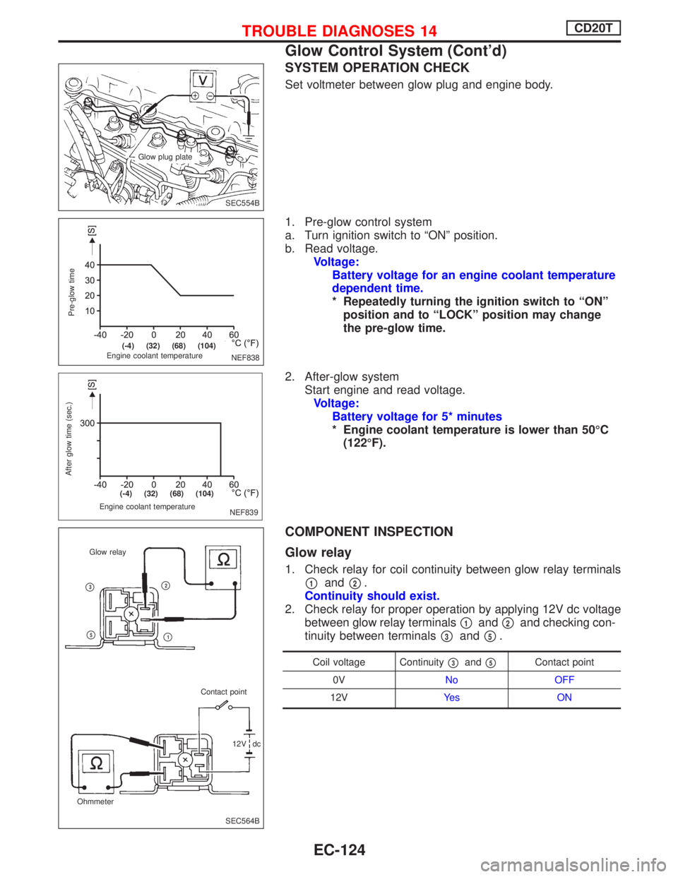
SYSTEM OPERATION CHECK
Set voltmeter between glow plug and engine body.
1. Pre-glow control system
a. Turn ignition switch to ªONº position.
b. Read voltage.
Voltage:
Battery voltage for an engine coolant temperature
dependent time.
* Repeatedly turning the ignition switch to ªONº
position and to ªLOCKº position may change
the pre-glow time.
2. After-glow system
Start engine and read voltage.
Voltage:
Battery voltage for 5* minutes
* Engine coolant temperature is lower than 50ÉC
(122ÉF).
COMPONENT INSPECTION
Glow relay
1. Check relay for coil continuity between glow relay terminals
p1andp2.
Continuity should exist.
2. Check relay for proper operation by applying 12V dc voltage
between glow relay terminals
p1andp2and checking con-
tinuity between terminals
p3andp5.
Coil voltage Continuityp3andp5Contact point
0VNo OFF
12VYe s O N
SEC554B Glow plug plate
NEF838
Pre-glow time
Engine coolant temperature
.(-4) (32) (68) (104)
NEF839 Engine coolant temperature
After glow time (sec.)
.(-4) (32) (68) (104)
SEC564B OhmmeterGlow relay
Contact point
12V dc
p2
p1
p3
p5
TROUBLE DIAGNOSES 14CD20T
Glow Control System (Cont'd)
EC-124