1999 NISSAN PRIMERA oil temperature
[x] Cancel search: oil temperaturePage 447 of 2267
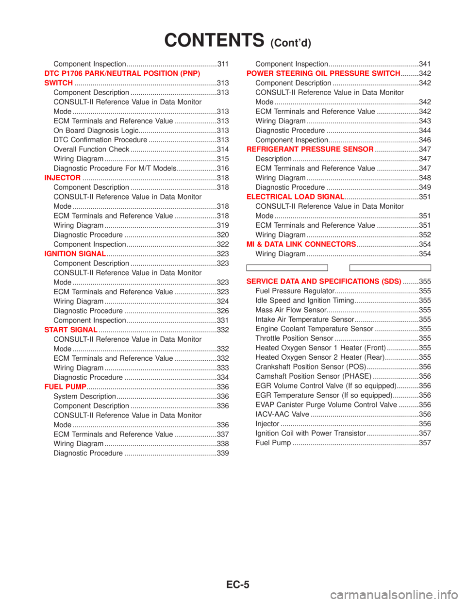
Component Inspection ............................................. 311
DTC P1706 PARK/NEUTRAL POSITION (PNP)
SWITCH.......................................................................313
Component Description ...........................................313
CONSULT-II Reference Value in Data Monitor
Mode ........................................................................313
ECM Terminals and Reference Value .....................313
On Board Diagnosis Logic.......................................313
DTC Confirmation Procedure ..................................313
Overall Function Check ...........................................314
Wiring Diagram ........................................................315
Diagnostic Procedure For M/T Models....................316
INJECTOR...................................................................318
Component Description ...........................................318
CONSULT-II Reference Value in Data Monitor
Mode ........................................................................318
ECM Terminals and Reference Value .....................318
Wiring Diagram ........................................................319
Diagnostic Procedure ..............................................320
Component Inspection .............................................322
IGNITION SIGNAL.......................................................323
Component Description ...........................................323
CONSULT-II Reference Value in Data Monitor
Mode ........................................................................323
ECM Terminals and Reference Value .....................323
Wiring Diagram ........................................................324
Diagnostic Procedure ..............................................326
Component Inspection .............................................331
START SIGNAL...........................................................332
CONSULT-II Reference Value in Data Monitor
Mode ........................................................................332
ECM Terminals and Reference Value .....................332
Wiring Diagram ........................................................333
Diagnostic Procedure ..............................................334
FUEL PUMP.................................................................336
System Description ..................................................336
Component Description ...........................................336
CONSULT-II Reference Value in Data Monitor
Mode ........................................................................336
ECM Terminals and Reference Value .....................337
Wiring Diagram ........................................................338
Diagnostic Procedure ..............................................339Component Inspection .............................................341
POWER STEERING OIL PRESSURE SWITCH.........342
Component Description ...........................................342
CONSULT-II Reference Value in Data Monitor
Mode ........................................................................342
ECM Terminals and Reference Value .....................342
Wiring Diagram ........................................................343
Diagnostic Procedure ..............................................344
Component Inspection .............................................346
REFRIGERANT PRESSURE SENSOR......................347
Description ...............................................................347
ECM Terminals and Reference Value .....................347
Wiring Diagram ........................................................348
Diagnostic Procedure ..............................................349
ELECTRICAL LOAD SIGNAL.....................................351
CONSULT-II Reference Value in Data Monitor
Mode ........................................................................351
ECM Terminals and Reference Value .....................351
Wiring Diagram ........................................................352
MI & DATA LINK CONNECTORS...............................354
Wiring Diagram ........................................................354
SERVICE DATA AND SPECIFICATIONS (SDS)........355
Fuel Pressure Regulator..........................................355
Idle Speed and Ignition Timing ................................355
Mass Air Flow Sensor..............................................355
Intake Air Temperature Sensor ................................355
Engine Coolant Temperature Sensor ......................355
Throttle Position Sensor ..........................................355
Heated Oxygen Sensor 1 Heater (Front) ................355
Heated Oxygen Sensor 2 Heater (Rear).................355
Crankshaft Position Sensor (POS) ..........................356
Camshaft Position Sensor (PHASE) .......................356
EGR Volume Control Valve (If so equipped)...........356
EGR Temperature Sensor (If so equipped).............356
EVAP Canister Purge Volume Control Valve ..........356
IACV-AAC Valve ......................................................356
Injector .....................................................................356
Ignition Coil with Power Transistor ..........................357
Fuel Pump ...............................................................357
CONTENTS(Cont'd)
EC-5
Page 462 of 2267
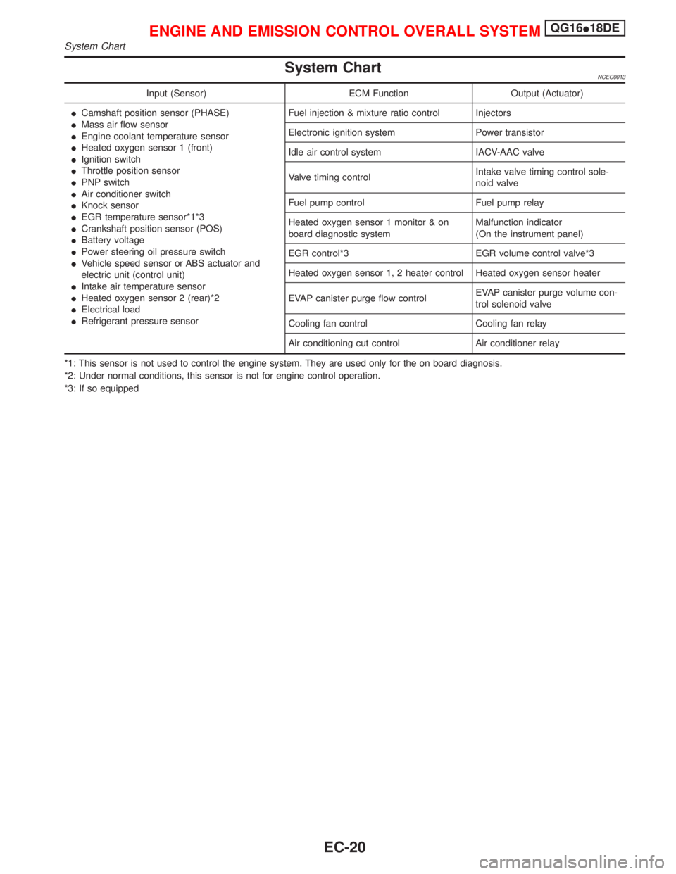
System ChartNCEC0013
Input (Sensor) ECM Function Output (Actuator)
ICamshaft position sensor (PHASE)
IMass air flow sensor
IEngine coolant temperature sensor
IHeated oxygen sensor 1 (front)
IIgnition switch
IThrottle position sensor
IPNP switch
IAir conditioner switch
IKnock sensor
IEGR temperature sensor*1*3
ICrankshaft position sensor (POS)
IBattery voltage
IPower steering oil pressure switch
IVehicle speed sensor or ABS actuator and
electric unit (control unit)
IIntake air temperature sensor
IHeated oxygen sensor 2 (rear)*2
IElectrical load
IRefrigerant pressure sensorFuel injection & mixture ratio control Injectors
Electronic ignition system Power transistor
Idle air control system IACV-AAC valve
Valve timing controlIntake valve timing control sole-
noid valve
Fuel pump control Fuel pump relay
Heated oxygen sensor 1 monitor & on
board diagnostic systemMalfunction indicator
(On the instrument panel)
EGR control*3 EGR volume control valve*3
Heated oxygen sensor 1, 2 heater control Heated oxygen sensor heater
EVAP canister purge flow controlEVAP canister purge volume con-
trol solenoid valve
Cooling fan control Cooling fan relay
Air conditioning cut control Air conditioner relay
*1: This sensor is not used to control the engine system. They are used only for the on board diagnosis.
*2: Under normal conditions, this sensor is not for engine control operation.
*3: If so equipped
ENGINE AND EMISSION CONTROL OVERALL SYSTEMQG16I18DE
System Chart
EC-20
Page 463 of 2267
Multiport Fuel Injection (MFI) System
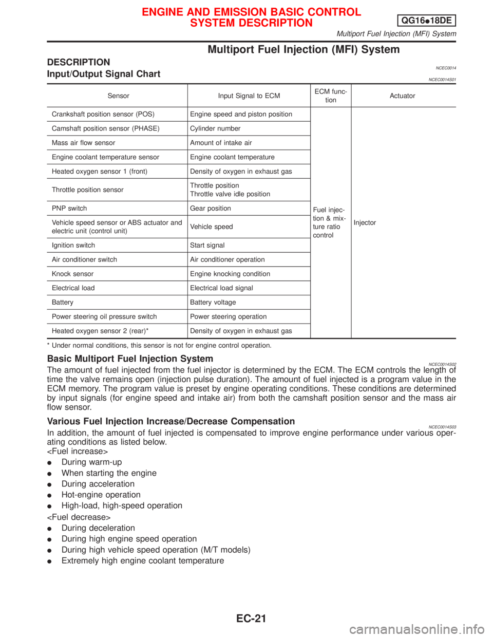
DESCRIPTIONNCEC0014Input/Output Signal ChartNCEC0014S01
Sensor Input Signal to ECMECM func-
tionActuator
Crankshaft position sensor (POS) Engine speed and piston position
Fuel injec-
tion & mix-
ture ratio
controlInjector Camshaft position sensor (PHASE) Cylinder number
Mass air flow sensor Amount of intake air
Engine coolant temperature sensor Engine coolant temperature
Heated oxygen sensor 1 (front) Density of oxygen in exhaust gas
Throttle position sensorThrottle position
Throttle valve idle position
PNP switch Gear position
Vehicle speed sensor or ABS actuator and
electric unit (control unit)Vehicle speed
Ignition switch Start signal
Air conditioner switch Air conditioner operation
Knock sensor Engine knocking condition
Electrical load Electrical load signal
Battery Battery voltage
Power steering oil pressure switch Power steering operation
Heated oxygen sensor 2 (rear)* Density of oxygen in exhaust gas
* Under normal conditions, this sensor is not for engine control operation.
Basic Multiport Fuel Injection SystemNCEC0014S02The amount of fuel injected from the fuel injector is determined by the ECM. The ECM controls the length of
time the valve remains open (injection pulse duration). The amount of fuel injected is a program value in the
ECM memory. The program value is preset by engine operating conditions. These conditions are determined
by input signals (for engine speed and intake air) from both the camshaft position sensor and the mass air
flow sensor.
Various Fuel Injection Increase/Decrease CompensationNCEC0014S03In addition, the amount of fuel injected is compensated to improve engine performance under various oper-
ating conditions as listed below.
IDuring warm-up
IWhen starting the engine
IDuring acceleration
IHot-engine operation
IHigh-load, high-speed operation
IDuring deceleration
IDuring high engine speed operation
IDuring high vehicle speed operation (M/T models)
IExtremely high engine coolant temperature
ENGINE AND EMISSION BASIC CONTROL
SYSTEM DESCRIPTIONQG16I18DE
Multiport Fuel Injection (MFI) System
EC-21
Page 466 of 2267
System DescriptionNCEC0015S02
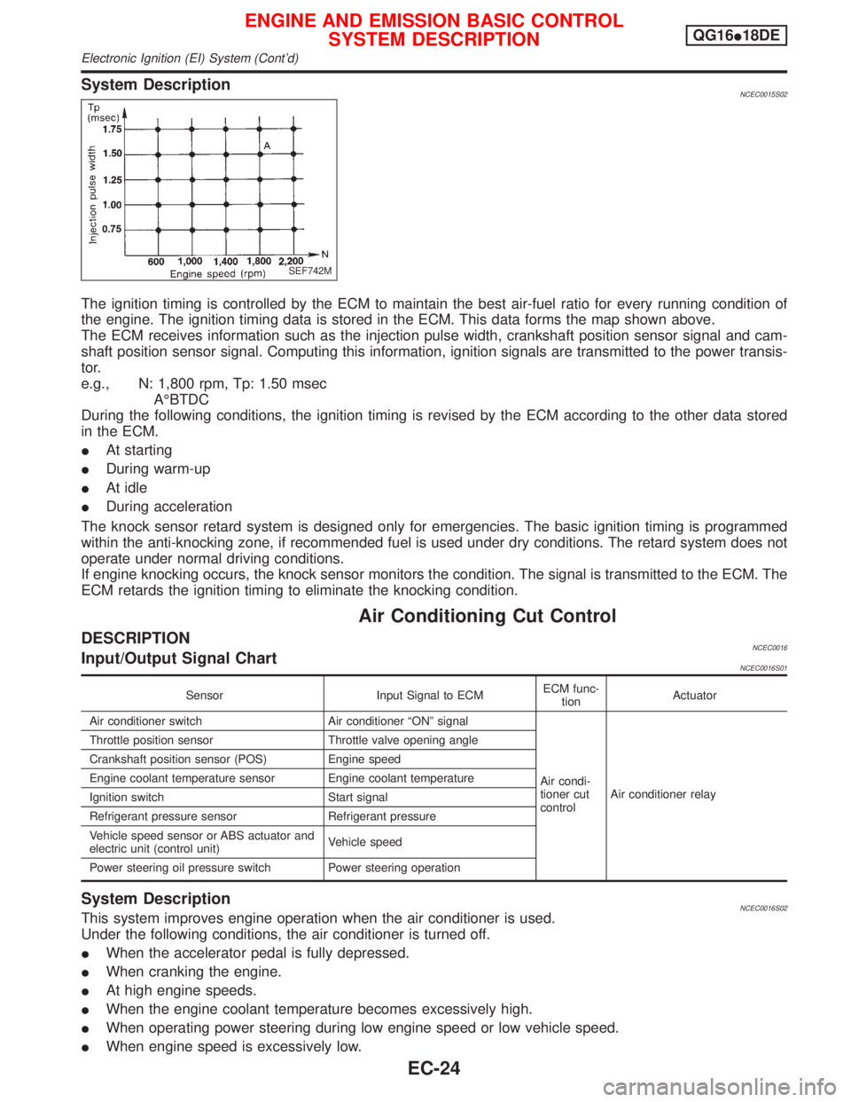
The ignition timing is controlled by the ECM to maintain the best air-fuel ratio for every running condition of
the engine. The ignition timing data is stored in the ECM. This data forms the map shown above.
The ECM receives information such as the injection pulse width, crankshaft position sensor signal and cam-
shaft position sensor signal. Computing this information, ignition signals are transmitted to the power transis-
tor.
e.g., N: 1,800 rpm, Tp: 1.50 msec
AÉBTDC
During the following conditions, the ignition timing is revised by the ECM according to the other data stored
in the ECM.
IAt starting
IDuring warm-up
IAt idle
IDuring acceleration
The knock sensor retard system is designed only for emergencies. The basic ignition timing is programmed
within the anti-knocking zone, if recommended fuel is used under dry conditions. The retard system does not
operate under normal driving conditions.
If engine knocking occurs, the knock sensor monitors the condition. The signal is transmitted to the ECM. The
ECM retards the ignition timing to eliminate the knocking condition.
Air Conditioning Cut Control
DESCRIPTIONNCEC0016Input/Output Signal ChartNCEC0016S01
Sensor Input Signal to ECMECM func-
tionActuator
Air conditioner switch Air conditioner ªONº signal
Air condi-
tioner cut
controlAir conditioner relay Throttle position sensor Throttle valve opening angle
Crankshaft position sensor (POS) Engine speed
Engine coolant temperature sensor Engine coolant temperature
Ignition switch Start signal
Refrigerant pressure sensor Refrigerant pressure
Vehicle speed sensor or ABS actuator and
electric unit (control unit)Vehicle speed
Power steering oil pressure switch Power steering operation
System DescriptionNCEC0016S02This system improves engine operation when the air conditioner is used.
Under the following conditions, the air conditioner is turned off.
IWhen the accelerator pedal is fully depressed.
IWhen cranking the engine.
IAt high engine speeds.
IWhen the engine coolant temperature becomes excessively high.
IWhen operating power steering during low engine speed or low vehicle speed.
IWhen engine speed is excessively low.
SEF742M
ENGINE AND EMISSION BASIC CONTROL
SYSTEM DESCRIPTIONQG16I18DE
Electronic Ignition (EI) System (Cont'd)
EC-24
Page 498 of 2267
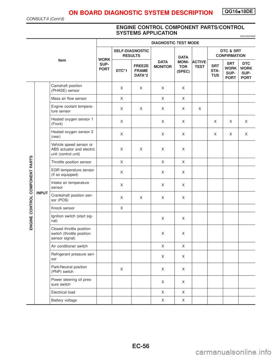
ENGINE CONTROL COMPONENT PARTS/CONTROL
SYSTEMS APPLICATION
NCEC0034S02
ItemDIAGNOSTIC TEST MODE
WORK
SUP-
PORTSELF-DIAGNOSTIC
RESULTS
D ATA
MONITORD ATA
MONI-
TOR
(SPEC)ACTIVE
TESTDTC & SRT
CONFIRMATION
DTC*1FREEZE
FRAME
DATA*2SRT
STA-
TUSSRT
WORK
SUP-
PORTDTC
WORK
SUP-
PORT
ENGINE CONTROL COMPONENT PARTS
INPUTCamshaft position
(PHASE) sensorXX X X
Mass air flow sensor X X X
Engine coolant tempera-
ture sensorXX X XX
Heated oxygen sensor 1
(Front)X X X XXX
Heated oxygen sensor 2
(rear)X X X XXX
Vehicle speed sensor or
ABS actuator and electric
unit (control unit)XX X X
Throttle position sensor X X X
EGR temperature sensor
(If so equipped)XXX
Intake air temperature
sensorXXX
Crankshaft position sen-
sor (POS)XX X X
Knock sensor X
Ignition switch (start sig-
nal)XX
Closed throttle position
switch (throttle position
sensor signal)XX
Air conditioner switch X X
Refrigerant pressure sen-
sorXX
Park/Neutral position
(PNP) switchXXX
Power steering oil pres-
sure switchXX
Electrical load X X
Battery voltage X X
ON BOARD DIAGNOSTIC SYSTEM DESCRIPTIONQG16I18DE
CONSULT-II (Cont'd)
EC-56
Page 504 of 2267
![NISSAN PRIMERA 1999 Electronic Repair Manual DATA MONITOR (SPEC) MODENLEC1365S07
Monitored item [Unit]ECM
input
signalsMain
signalsDescription Remarks
MAS A/F SE-B1 [V]qqIThe signal voltage of the mass air flow sen-
sor specification is displaye NISSAN PRIMERA 1999 Electronic Repair Manual DATA MONITOR (SPEC) MODENLEC1365S07
Monitored item [Unit]ECM
input
signalsMain
signalsDescription Remarks
MAS A/F SE-B1 [V]qqIThe signal voltage of the mass air flow sen-
sor specification is displaye](/manual-img/5/57377/w960_57377-503.png)
DATA MONITOR (SPEC) MODENLEC1365S07
Monitored item [Unit]ECM
input
signalsMain
signalsDescription Remarks
MAS A/F SE-B1 [V]qqIThe signal voltage of the mass air flow sen-
sor specification is displayed.IWhen the engine is running, specifi-
cation range is indicated.
B/FUEL SCHDL
[msec]IªBase fuel scheduleº indicates the fuel injec-
tion pulse width programmed into ECM,
prior to any learned on board correction.IWhen the engine is running, specifi-
cation range is indicated.
A/F ALPHA-B1 [%]qIIndicates the mean value of the air-fuel ratio
feedback correction factor per cycle.IWhen the engine is running, specifi-
cation range is indicated.
IThis data also includes the data for
the air-fuel ratio learning control.
NOTE:
Any monitored item that does not match the vehicle being diagnosed is deleted from the display automatically.
ACTIVE TEST MODENCEC0034S07
TEST ITEM CONDITION JUDGEMENT CHECK ITEM (REMEDY)
FUEL INJECTIONIEngine: Return to the original
trouble condition
IChange the amount of fuel injec-
tion using CONSULT-II.If trouble symptom disappears, see
CHECK ITEM.IHarness and connector
IFuel injectors
IHeated oxygen sensor 1 (front)
IACV-AAC/V
OPENINGIEngine: After warming up, idle
the engine.
IChange the IACV-AAC valve
opening steps using CONSULT-
II.Engine speed changes according
to the opening steps.IHarness and connector
IIACV-AAC valve
ENG COOLANT
TEMPIEngine: Return to the original
trouble condition
IChange the engine coolant tem-
perature indication using CON-
SULT-II.If trouble symptom disappears, see
CHECK ITEM.IHarness and connector
IEngine coolant temperature sen-
sor
IFuel injectors
IGNITION TIMINGIEngine: Return to the original
trouble condition
ITiming light: Set
IRetard the ignition timing using
CONSULT-II.If trouble symptom disappears, see
CHECK ITEM.IªBase Idle Air Volume Initializingº
(Refer to EC-QG-33.)
ICamshaft position sensor
(PHASE)
ICrankshaft position sensor
(POS)
IEngine component parts and
installing conditions
POWER BAL-
ANCEIEngine: After warming up, idle
the engine.
IAir conditioner switch ªOFFº
IShift lever ªNº
ICut off each injector signal one
at a time using CONSULT-II.Engine runs rough or dies.IHarness and connector
ICompression
IInjectors
IPower transistor
ISpark plugs
IIgnition coils
COOLING FANIIgnition switch: ON
ITurn the cooling fan ªONº and
ªOFFº using CONSULT-II.Cooling fan moves and stops.IHarness and connector
ICooling fan motor
FUEL PUMP
RELAYIIgnition switch: ON
(Engine stopped)
ITurn the fuel pump relay ªONº
and ªOFFº using CONSULT-II
and listen to operating sound.Fuel pump relay makes the operat-
ing sound.IHarness and connector
IFuel pump relay
ON BOARD DIAGNOSTIC SYSTEM DESCRIPTIONQG16I18DE
CONSULT-II (Cont'd)
EC-62
Page 524 of 2267
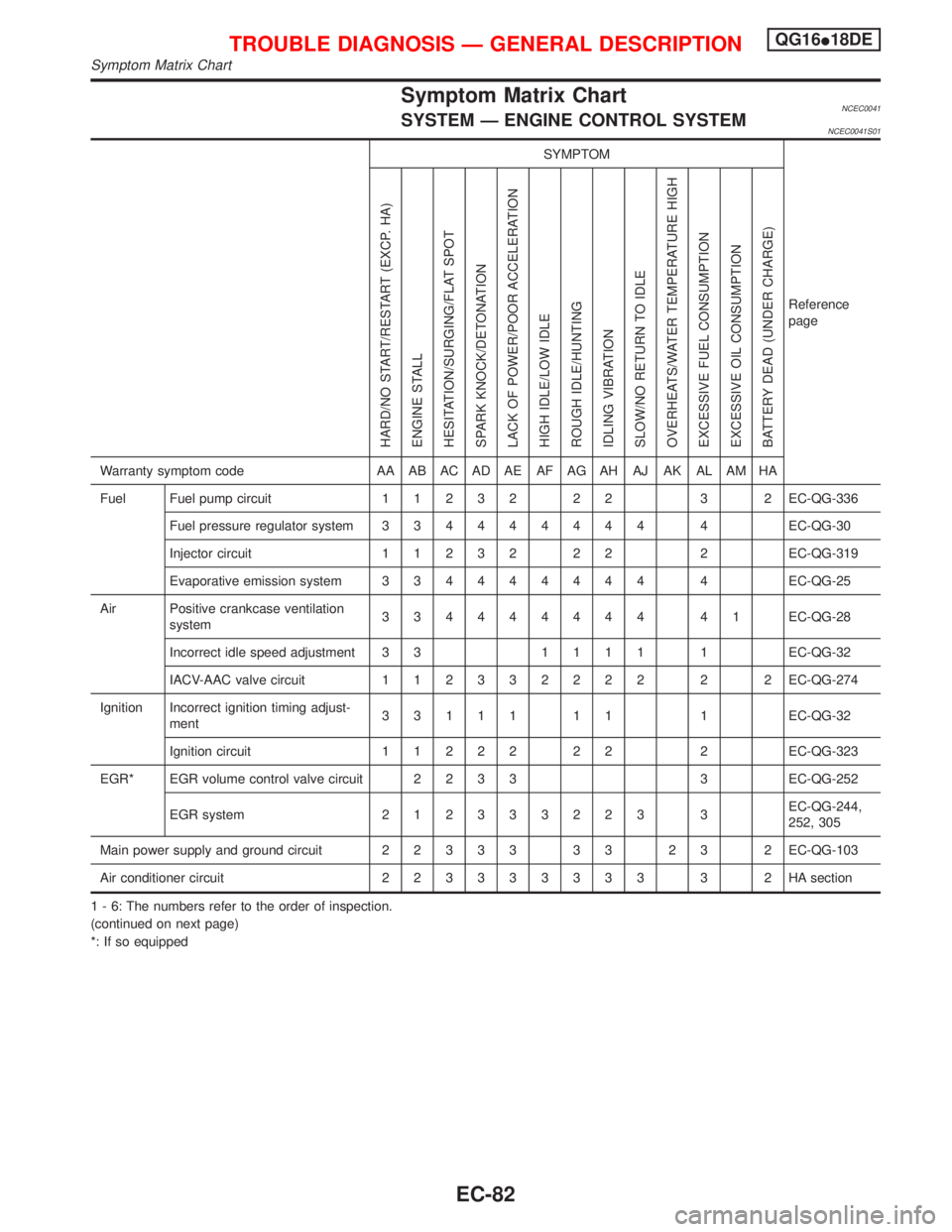
Symptom Matrix ChartNCEC0041SYSTEM Ð ENGINE CONTROL SYSTEMNCEC0041S01
SYMPTOM
Reference
page
HARD/NO START/RESTART (EXCP. HA)
ENGINE STALL
HESITATION/SURGING/FLAT SPOT
SPARK KNOCK/DETONATION
LACK OF POWER/POOR ACCELERATION
HIGH IDLE/LOW IDLE
ROUGH IDLE/HUNTING
IDLING VIBRATION
SLOW/NO RETURN TO IDLE
OVERHEATS/WATER TEMPERATURE HIGH
EXCESSIVE FUEL CONSUMPTION
EXCESSIVE OIL CONSUMPTION
BATTERY DEAD (UNDER CHARGE)
Warranty symptom code AA AB AC AD AE AF AG AH AJ AK AL AM HA
Fuel Fuel pump circuit11232 22 3 2EC-QG-336
Fuel pressure regulator system334444444 4EC-QG-30
Injector circuit11232 22 2EC-QG-319
Evaporative emission system334444444 4EC-QG-25
Air Positive crankcase ventilation
system334444444 41EC-QG-28
Incorrect idle speed adjustment 3 31111 1EC-QG-32
IACV-AAC valve circuit112332222 2 2EC-QG-274
Ignition Incorrect ignition timing adjust-
ment33111 11 1EC-QG-32
Ignition circuit11222 22 2EC-QG-323
EGR* EGR volume control valve circuit2233 3EC-QG-252
EGR system212333223 3EC-QG-244,
252, 305
Main power supply and ground circuit22333 33 23 2EC-QG-103
Air conditioner circuit223333333 3 2HAsection
1 - 6: The numbers refer to the order of inspection.
(continued on next page)
*: If so equipped
TROUBLE DIAGNOSIS Ð GENERAL DESCRIPTIONQG16I18DE
Symptom Matrix Chart
EC-82
Page 525 of 2267
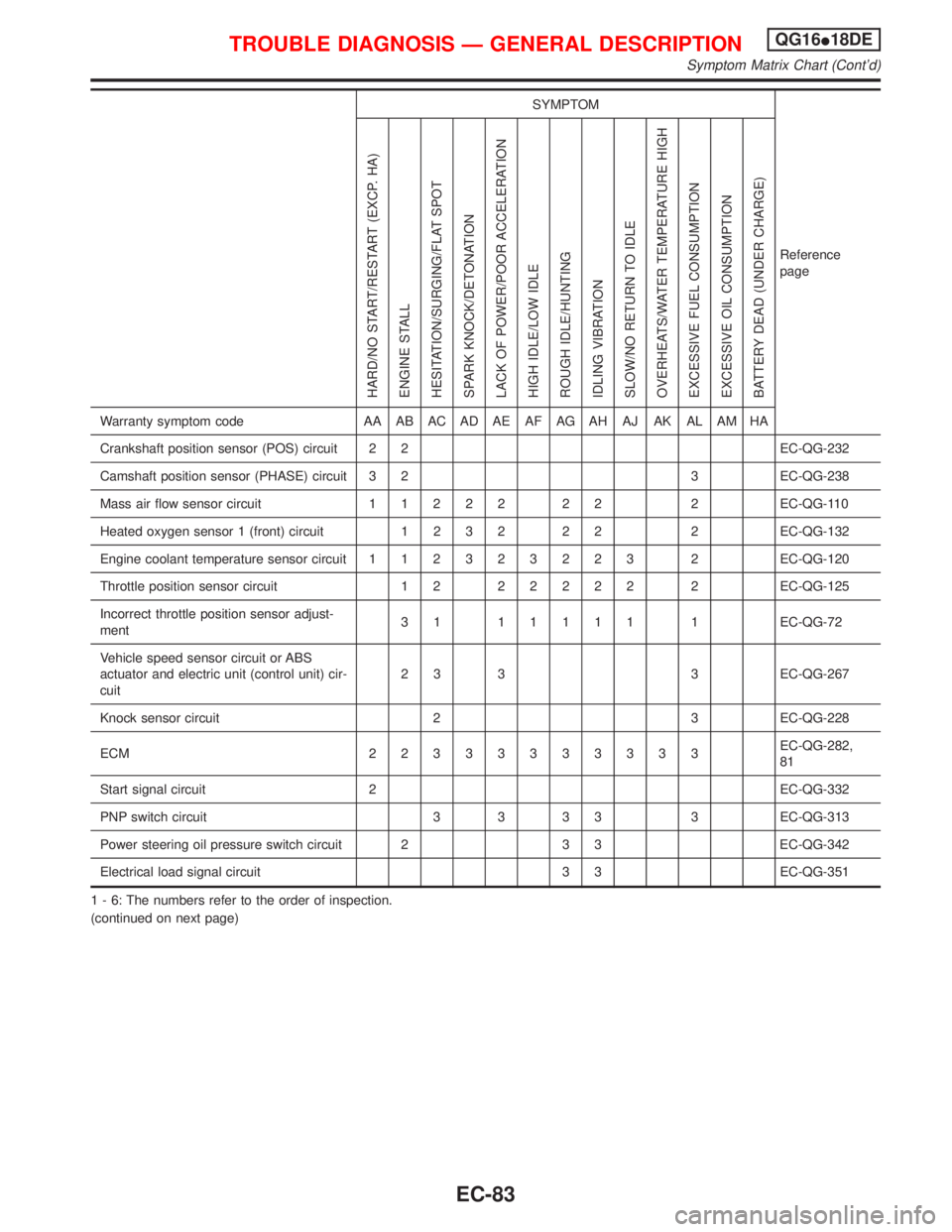
SYMPTOM
Reference
page
HARD/NO START/RESTART (EXCP. HA)
ENGINE STALL
HESITATION/SURGING/FLAT SPOT
SPARK KNOCK/DETONATION
LACK OF POWER/POOR ACCELERATION
HIGH IDLE/LOW IDLE
ROUGH IDLE/HUNTING
IDLING VIBRATION
SLOW/NO RETURN TO IDLE
OVERHEATS/WATER TEMPERATURE HIGH
EXCESSIVE FUEL CONSUMPTION
EXCESSIVE OIL CONSUMPTION
BATTERY DEAD (UNDER CHARGE)
Warranty symptom code AA AB AC AD AE AF AG AH AJ AK AL AM HA
Crankshaft position sensor (POS) circuit 2 2 EC-QG-232
Camshaft position sensor (PHASE) circuit 3 2 3 EC-QG-238
Mass air flow sensor circuit11222 22 2EC-QG-110
Heated oxygen sensor 1 (front) circuit1232 22 2EC-QG-132
Engine coolant temperature sensor circuit112323223 2EC-QG-120
Throttle position sensor circuit 1 222222 2EC-QG-125
Incorrect throttle position sensor adjust-
ment31 11111 1EC-QG-72
Vehicle speed sensor circuit or ABS
actuator and electric unit (control unit) cir-
cuit2 3 3 3 EC-QG-267
Knock sensor circuit 2 3 EC-QG-228
ECM 22333333333EC-QG-282,
81
Start signal circuit 2 EC-QG-332
PNP switch circuit 3 3 3 3 3 EC-QG-313
Power steering oil pressure switch circuit 2 3 3 EC-QG-342
Electrical load signal circuit 3 3 EC-QG-351
1 - 6: The numbers refer to the order of inspection.
(continued on next page)
TROUBLE DIAGNOSIS Ð GENERAL DESCRIPTIONQG16I18DE
Symptom Matrix Chart (Cont'd)
EC-83