1999 NISSAN PRIMERA oil temperature
[x] Cancel search: oil temperaturePage 1583 of 2267
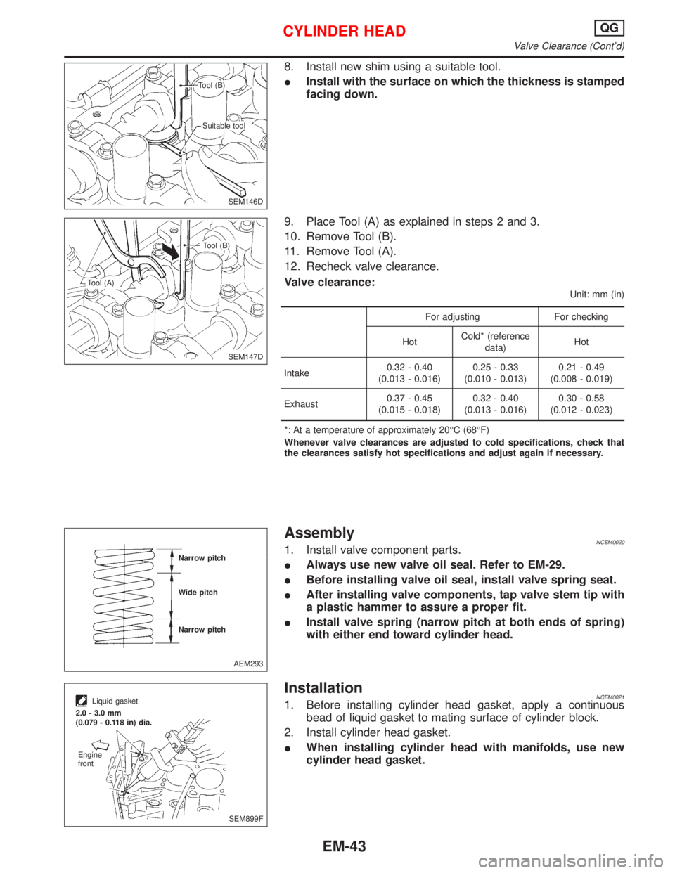
8. Install new shim using a suitable tool.
IInstall with the surface on which the thickness is stamped
facing down.
9. Place Tool (A) as explained in steps 2 and 3.
10. Remove Tool (B).
11. Remove Tool (A).
12. Recheck valve clearance.
Valve clearance:
Unit: mm (in)
For adjusting For checking
HotCold* (reference
data)Hot
Intake0.32 - 0.40
(0.013 - 0.016)0.25 - 0.33
(0.010 - 0.013)0.21 - 0.49
(0.008 - 0.019)
Exhaust0.37 - 0.45
(0.015 - 0.018)0.32 - 0.40
(0.013 - 0.016)0.30 - 0.58
(0.012 - 0.023)
*: At a temperature of approximately 20ÉC (68ÉF)
Whenever valve clearances are adjusted to cold specifications, check that
the clearances satisfy hot specifications and adjust again if necessary.
AssemblyNCEM00201. Install valve component parts.
IAlways use new valve oil seal. Refer to EM-29.
IBefore installing valve oil seal, install valve spring seat.
IAfter installing valve components, tap valve stem tip with
a plastic hammer to assure a proper fit.
IInstall valve spring (narrow pitch at both ends of spring)
with either end toward cylinder head.
InstallationNCEM00211. Before installing cylinder head gasket, apply a continuous
bead of liquid gasket to mating surface of cylinder block.
2. Install cylinder head gasket.
IWhen installing cylinder head with manifolds, use new
cylinder head gasket.
SEM146D Tool (B)
Suitable tool
SEM147D Tool (B)
Tool (A)
AEM293 Narrow pitch
Wide pitch
Narrow pitch
SEM899F
Liquid gasket
2.0 - 3.0 mm
(0.079 - 0.118 in) dia.
Engine
front
CYLINDER HEADQG
Valve Clearance (Cont'd)
EM-43
Page 1593 of 2267
Removal and InstallationNCEM0024CAUTION:
IWhen installing sliding parts such as bearings and
pistons, apply engine oil on the sliding surfaces.
IPlace removed parts, such as bearings and bearing caps,
in their proper order and direction.
IWhen installing connecting rod nuts and main bearing cap
bolts, apply new engine oil to threads and seating sur-
faces.
IDo not allow any magnetic materials to contact the signal
plate teeth of flywheel or drive plate, and rear plate.
IRemove the crankshaft position sensor (POS).
IBe careful not to damage sensor edges and single plate
teeth.
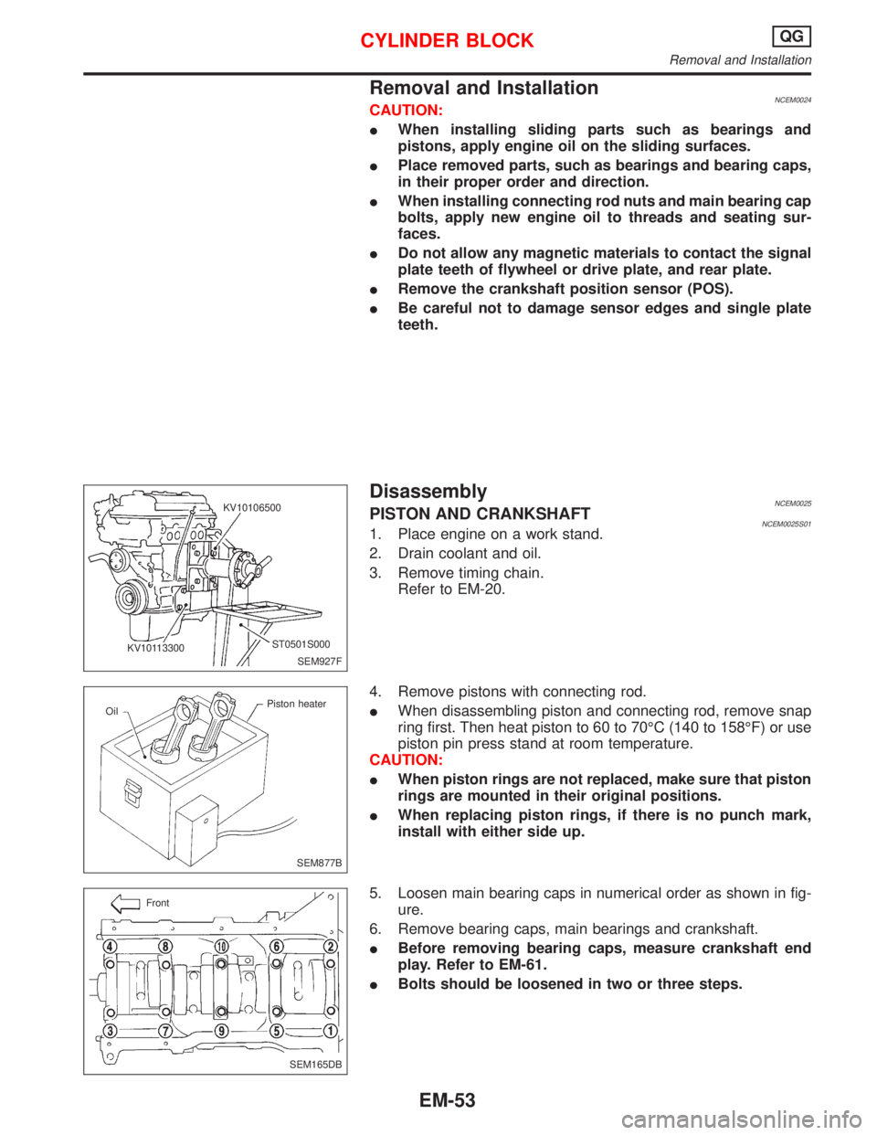
DisassemblyNCEM0025PISTON AND CRANKSHAFTNCEM0025S011. Place engine on a work stand.
2. Drain coolant and oil.
3. Remove timing chain.
Refer to EM-20.
4. Remove pistons with connecting rod.
IWhen disassembling piston and connecting rod, remove snap
ring first. Then heat piston to 60 to 70ÉC (140 to 158ÉF) or use
piston pin press stand at room temperature.
CAUTION:
IWhen piston rings are not replaced, make sure that piston
rings are mounted in their original positions.
IWhen replacing piston rings, if there is no punch mark,
install with either side up.
5. Loosen main bearing caps in numerical order as shown in fig-
ure.
6. Remove bearing caps, main bearings and crankshaft.
IBefore removing bearing caps, measure crankshaft end
play. Refer to EM-61.
IBolts should be loosened in two or three steps.
SEM927F KV10106500
ST0501S000
KV10113300
SEM877B OilPiston heater
SEM165DB Front
CYLINDER BLOCKQG
Removal and Installation
EM-53
Page 1650 of 2267
CAUTION:
IWhen installing sliding parts (bearings, pistons, etc.),
apply new engine oil to the sliding surfaces.
IPlace removed parts such as bearings and bearing caps
in their correct order and direction.
IWhen installing connecting rod nuts and main bearing cap
bolts, apply new engine oil to threads and seating sur-
faces.
IDo not allow any magnetic materials to contact the ring
gear teeth of flywheel/drive plate.
Disassembly
PISTON AND CRANKSHAFT
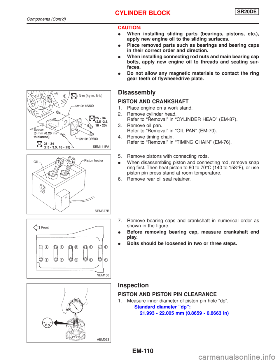
1. Place engine on a work stand.
2. Remove cylinder head.
Refer to ªRemovalº in ªCYLINDER HEADº (EM-87).
3. Remove oil pan.
Refer to ªRemovalº in ªOIL PANº (EM-70).
4. Remove timing chain.
Refer to ªRemovalº in ªTIMING CHAINº (EM-76).
5. Remove pistons with connecting rods.
IWhen disassembling piston and connecting rod, remove snap
ring first. Then heat piston to 60 to 70ÉC (140 to 158ÉF), or use
piston pin press stand at room temperature.
6. Remove rear oil seal retainer.
7. Remove bearing caps and crankshaft in numerical order as
shown in the figure.
IBefore removing bearing cap, measure crankshaft end
play.
IBolts should be loosened in two or three steps.
Inspection
PISTON AND PISTON PIN CLEARANCE
1. Measure inner diameter of piston pin hole ªdpº.
Standard diameter ªdpº:
21.993 - 22.005 mm (0.8659 - 0.8663 in)
SEM141FA
: N´m (kg-m, ft-lb)
25-34
(2.5 -3.5,
18 - 25)
Spacer
[5 mm (0.20 in)
thickness]
25-34
(2.5 - 3.5, 18 - 25)
SEM877B Piston heater
Oil
NEM150 Front
p2
p1
p4
p3
p8
p7
p10
p9
p6
p5
AEM023
CYLINDER BLOCKSR20DE
Components (Cont'd)
EM-110
Page 1707 of 2267
Preparation
IDrill a hole into the attachment (KV10108101).
Disassembly
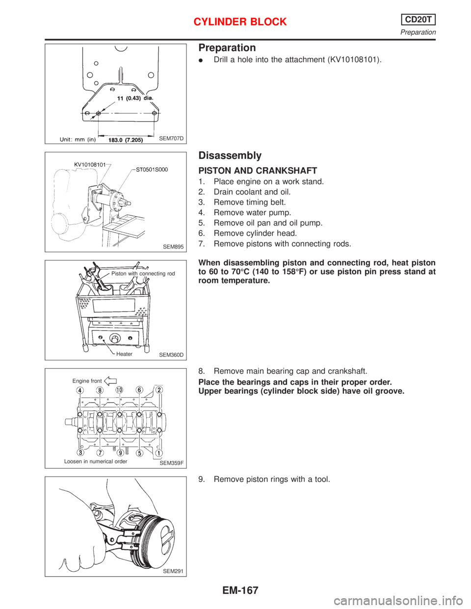
PISTON AND CRANKSHAFT
1. Place engine on a work stand.
2. Drain coolant and oil.
3. Remove timing belt.
4. Remove water pump.
5. Remove oil pan and oil pump.
6. Remove cylinder head.
7. Remove pistons with connecting rods.
When disassembling piston and connecting rod, heat piston
to 60 to 70ÉC (140 to 158ÉF) or use piston pin press stand at
room temperature.
8. Remove main bearing cap and crankshaft.
Place the bearings and caps in their proper order.
Upper bearings (cylinder block side) have oil groove.
9. Remove piston rings with a tool.
SEM707D
SEM895
SEM360D Piston with connecting rod
Heater
SEM359F Engine front
Loosen in numerical order
SEM291
CYLINDER BLOCKCD20T
Preparation
EM-167
Page 1733 of 2267
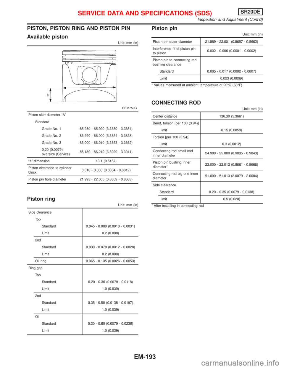
PISTON, PISTON RING AND PISTON PIN
Available piston
Unit: mm (in)
SEM750C
Piston skirt diameter ªAº
Standard
Grade No. 1 85.980 - 85.990 (3.3850 - 3.3854)
Grade No. 2 85.990 - 86.000 (3.3854 - 3.3858)
Grade No. 3 86.000 - 86.010 (3.3858 - 3.3862)
0.20 (0.0079)
oversize (Service)86.180 - 86.210 (3.3929 - 3.3941)
ªaº dimension 13.1 (0.5157)
Piston clearance to cylinder
block0.010 - 0.030 (0.0004 - 0.0012)
Piston pin hole diameter 21.993 - 22.005 (0.8659 - 0.8663)
Piston ring
Unit: mm (in)
Side clearance
To p
Standard 0.045 - 0.080 (0.0018 - 0.0031)
Limit 0.2 (0.008)
2nd
Standard 0.030 - 0.070 (0.0012 - 0.0028)
Limit 0.2 (0.008)
Oil ring 0.065 - 0.135 (0.0026 - 0.0053)
Ring gap
To p
Standard 0.20 - 0.30 (0.0079 - 0.0118)
Limit 1.0 (0.039)
2nd
Standard 0.35 - 0.50 (0.0138 - 0.0197)
Limit 1.0 (0.039)
Oil
Standard 0.20 - 0.60 (0.0079 - 0.0236)
Limit 1.0 (0.039)
Piston pin
Unit: mm (in)
Piston pin outer diameter 21.989 - 22.001 (0.8657 - 0.8662)
Interference fit of piston pin
to piston0.002 - 0.006 (0.0001 - 0.0002)
Piston pin to connecting rod
bushing clearance
Standard 0.005 - 0.017 (0.0002 - 0.0007)
Limit 0.023 (0.0009)
* Values measured at ambient temperature of 20ÉC (68ÉF)
CONNECTING ROD
Unit: mm (in)
Center distance 136.30 (5.3661)
Bend, torsion [per 100 (3.94)]
Limit 0.15 (0.0059)
Torsion [per 100 (3.94)]
Limit 0.3 (0.0012)
Connecting rod small end
inner diameter24.980 - 25.000 (0.9835 - 0.9843)
Piston pin bushing inner
diameter*22.000 - 22.012 (0.8661 - 0.8666)
Connecting rod big end inner
diameter51.000 - 51.013 (2.0079 - 2.0084)
Side clearance
Standard 0.20 - 0.35 (0.0079 - 0.0138)
Limit 0.5 (0.020)
* After installing in connecting rod
SERVICE DATA AND SPECIFICATIONS (SDS)SR20DE
Inspection and Adjustment (Cont'd)
EM-193
Page 1801 of 2267
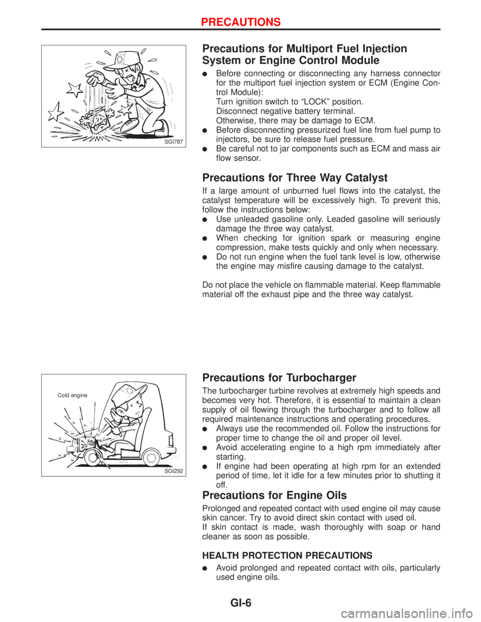
Precautions for Multiport Fuel Injection
System or Engine Control Module
lBefore connecting or disconnecting any harness connector
for the multiport fuel injection system or ECM (Engine Con-
trol Module):
Turn ignition switch to ªLOCKº position.
Disconnect negative battery terminal.
Otherwise, there may be damage to ECM.
lBefore disconnecting pressurized fuel line from fuel pump to
injectors, be sure to release fuel pressure.
lBe careful not to jar components such as ECM and mass air
flow sensor.
Precautions for Three Way Catalyst
If a large amount of unburned fuel flows into the catalyst, the
catalyst temperature will be excessively high. To prevent this,
follow the instructions below:
lUse unleaded gasoline only. Leaded gasoline will seriously
damage the three way catalyst.
lWhen checking for ignition spark or measuring engine
compression, make tests quickly and only when necessary.
lDo not run engine when the fuel tank level is low, otherwise
the engine may misfire causing damage to the catalyst.
Do not place the vehicle on flammable material. Keep flammable
material off the exhaust pipe and the three way catalyst.
Precautions for Turbocharger
The turbocharger turbine revolves at extremely high speeds and
becomes very hot. Therefore, it is essential to maintain a clean
supply of oil flowing through the turbocharger and to follow all
required maintenance instructions and operating procedures.
lAlways use the recommended oil. Follow the instructions for
proper time to change the oil and proper oil level.
lAvoid accelerating engine to a high rpm immediately after
starting.
lIf engine had been operating at high rpm for an extended
period of time, let it idle for a few minutes prior to shutting it
off.
Precautions for Engine Oils
Prolonged and repeated contact with used engine oil may cause
skin cancer. Try to avoid direct skin contact with used oil.
If skin contact is made, wash thoroughly with soap or hand
cleaner as soon as possible.
HEALTH PROTECTION PRECAUTIONS
lAvoid prolonged and repeated contact with oils, particularly
used engine oils.
SGI787
SGI292 Cold engine
PRECAUTIONS
GI-6
Page 1802 of 2267
lWear protective clothing, including impervious gloves where
practicable.
lDo not put oily rags in pockets.
lAvoid contaminating clothes, particularly underpants, with oil.
lHeavily soiled clothing and oil-impregnated footwear should
not be worn. Overalls must be cleaned regularly.
lFirst Aid treatment should be obtained immediately for open
cuts and wounds.
lUse barrier creams, applying them before each work period,
to help the removal of oil from the skin.
lWash with soap and water to ensure all oil is removed (skin
cleansers and nail brushes will help). Preparations contain-
ing lanolin replace the natural skin oils which have been
removed.
lDo not use gasoline, kerosine, diesel fuel, gas oil, thinners
or solvents for cleaning skin.
lIf skin disorders develop, obtain medical advice without
delay.
lWhere practicable, degrease components prior to handling.
lWhere there is a risk of eye contact, eye protection should
be worn, for example, chemical goggles or face shields; in
addition an eye wash facility should be provided.
ENVIRONMENTAL PROTECTION PRECAUTIONS
Burning used engine oil in small space heaters or boilers can be
recommended only for units of approved design. The heating
system must meet the requirements of HM Inspectorate of Pol-
lution for small burners of less than 0.4 MW. If in doubt check
with the appropriate local authority and/or manufacturer of the
approved appliance.
Dispose of used oil and used oil filters through authorized waste
disposal contractors to licensed waste disposal sites, or to the
waste oil reclamation trade. If in doubt, contact the local author-
ity for advice on disposal facilities.
It is illegal to pour used oil on to the ground, down sewers or
drains, or into water courses.
The regulations concerning the pollution of the environment
will vary between regions.
Precautions for Fuel
GASOLINE ENGINE:
Unleaded gasoline of at least 95 octane (RON)
CAUTION:
Do not use leaded gasoline. Using leaded gasoline will dam-
age the catalytic converter.
DIESEL ENGINE*:
Diesel fuel of at least 50 cetane
* If two types of diesel fuel are available, use summer or win-
ter fuel properly according to the following temperature con-
ditions.
lAbove þ7ÉC (20ÉF) ... Summer type diesel fuel.
lBelow þ7ÉC (20ÉF) ... Winter type diesel fuel.
PRECAUTIONS
Precautions for Engine Oils (Cont'd)
GI-7
Page 1803 of 2267
CAUTION:
lDo not use home heating oil, gasoline, or other alternate
fuels in your diesel engine. The use of those can cause
engine damage.
lDo not use summer fuel at temperatures below þ7ÉC
(20ÉF). Cold temperatures will cause wax to form in the
fuel, as a result, it may prevent the engine from running
smoothly.
lDo not add gasoline or other alternative fuels to diesel
fuel.
Precautions for Air Conditioning
Use an approved refrigerant recovery unit any time the air con-
ditioning system must be discharged. Refer to HA section (ªHFC-
134a (R134a) Service Procedureº, ªSERVICE PROCEDURESº)
for specific instructions.
PRECAUTIONS
Precautions for Fuel (Cont'd)
GI-8