1999 NISSAN PRIMERA power steering fluid
[x] Cancel search: power steering fluidPage 1156 of 2267
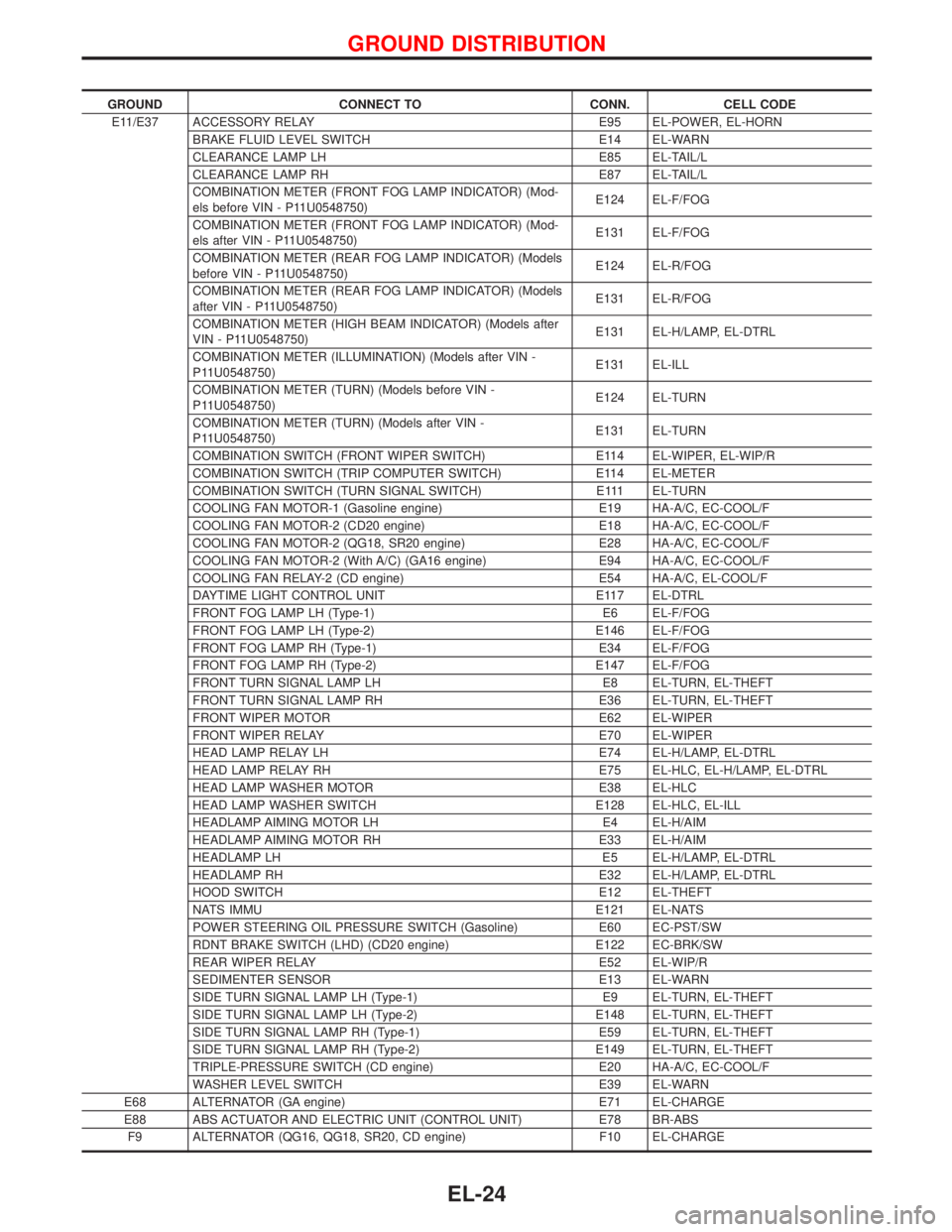
GROUND CONNECT TO CONN. CELL CODE
E11/E37 ACCESSORY RELAY E95 EL-POWER, EL-HORN
BRAKE FLUID LEVEL SWITCH E14 EL-WARN
CLEARANCE LAMP LH E85 EL-TAIL/L
CLEARANCE LAMP RH E87 EL-TAIL/L
COMBINATION METER (FRONT FOG LAMP INDICATOR) (Mod-
els before VIN - P11U0548750)E124 EL-F/FOG
COMBINATION METER (FRONT FOG LAMP INDICATOR) (Mod-
els after VIN - P11U0548750)E131 EL-F/FOG
COMBINATION METER (REAR FOG LAMP INDICATOR) (Models
before VIN - P11U0548750)E124 EL-R/FOG
COMBINATION METER (REAR FOG LAMP INDICATOR) (Models
after VIN - P11U0548750)E131 EL-R/FOG
COMBINATION METER (HIGH BEAM INDICATOR) (Models after
VIN - P11U0548750)E131 EL-H/LAMP, EL-DTRL
COMBINATION METER (ILLUMINATION) (Models after VIN -
P11U0548750)E131 EL-ILL
COMBINATION METER (TURN) (Models before VIN -
P11U0548750)E124 EL-TURN
COMBINATION METER (TURN) (Models after VIN -
P11U0548750)E131 EL-TURN
COMBINATION SWITCH (FRONT WIPER SWITCH) E114 EL-WIPER, EL-WIP/R
COMBINATION SWITCH (TRIP COMPUTER SWITCH) E114 EL-METER
COMBINATION SWITCH (TURN SIGNAL SWITCH) E111 EL-TURN
COOLING FAN MOTOR-1 (Gasoline engine) E19 HA-A/C, EC-COOL/F
COOLING FAN MOTOR-2 (CD20 engine) E18 HA-A/C, EC-COOL/F
COOLING FAN MOTOR-2 (QG18, SR20 engine) E28 HA-A/C, EC-COOL/F
COOLING FAN MOTOR-2 (With A/C) (GA16 engine) E94 HA-A/C, EC-COOL/F
COOLING FAN RELAY-2 (CD engine) E54 HA-A/C, EL-COOL/F
DAYTIME LIGHT CONTROL UNIT E117 EL-DTRL
FRONT FOG LAMP LH (Type-1) E6 EL-F/FOG
FRONT FOG LAMP LH (Type-2) E146 EL-F/FOG
FRONT FOG LAMP RH (Type-1) E34 EL-F/FOG
FRONT FOG LAMP RH (Type-2) E147 EL-F/FOG
FRONT TURN SIGNAL LAMP LH E8 EL-TURN, EL-THEFT
FRONT TURN SIGNAL LAMP RH E36 EL-TURN, EL-THEFT
FRONT WIPER MOTOR E62 EL-WIPER
FRONT WIPER RELAY E70 EL-WIPER
HEAD LAMP RELAY LH E74 EL-H/LAMP, EL-DTRL
HEAD LAMP RELAY RH E75 EL-HLC, EL-H/LAMP, EL-DTRL
HEAD LAMP WASHER MOTOR E38 EL-HLC
HEAD LAMP WASHER SWITCH E128 EL-HLC, EL-ILL
HEADLAMP AIMING MOTOR LH E4 EL-H/AIM
HEADLAMP AIMING MOTOR RH E33 EL-H/AIM
HEADLAMP LH E5 EL-H/LAMP, EL-DTRL
HEADLAMP RH E32 EL-H/LAMP, EL-DTRL
HOOD SWITCH E12 EL-THEFT
NATS IMMU E121 EL-NATS
POWER STEERING OIL PRESSURE SWITCH (Gasoline) E60 EC-PST/SW
RDNT BRAKE SWITCH (LHD) (CD20 engine) E122 EC-BRK/SW
REAR WIPER RELAY E52 EL-WIP/R
SEDIMENTER SENSOR E13 EL-WARN
SIDE TURN SIGNAL LAMP LH (Type-1) E9 EL-TURN, EL-THEFT
SIDE TURN SIGNAL LAMP LH (Type-2) E148 EL-TURN, EL-THEFT
SIDE TURN SIGNAL LAMP RH (Type-1) E59 EL-TURN, EL-THEFT
SIDE TURN SIGNAL LAMP RH (Type-2) E149 EL-TURN, EL-THEFT
TRIPLE-PRESSURE SWITCH (CD engine) E20 HA-A/C, EC-COOL/F
WASHER LEVEL SWITCH E39 EL-WARN
E68 ALTERNATOR (GA engine) E71 EL-CHARGE
E88 ABS ACTUATOR AND ELECTRIC UNIT (CONTROL UNIT) E78 BR-ABS
F9 ALTERNATOR (QG16, QG18, SR20, CD engine) F10 EL-CHARGE
GROUND DISTRIBUTION
EL-24
Page 1568 of 2267
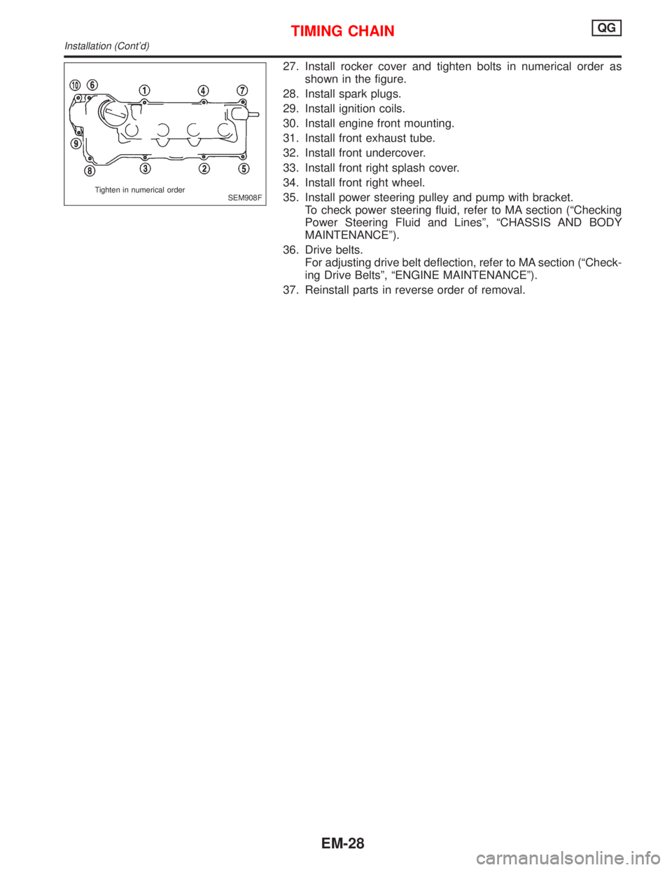
27. Install rocker cover and tighten bolts in numerical order as
shown in the figure.
28. Install spark plugs.
29. Install ignition coils.
30. Install engine front mounting.
31. Install front exhaust tube.
32. Install front undercover.
33. Install front right splash cover.
34. Install front right wheel.
35. Install power steering pulley and pump with bracket.
To check power steering fluid, refer to MA section (ªChecking
Power Steering Fluid and Linesº, ªCHASSIS AND BODY
MAINTENANCEº).
36. Drive belts.
For adjusting drive belt deflection, refer to MA section (ªCheck-
ing Drive Beltsº, ªENGINE MAINTENANCEº).
37. Reinstall parts in reverse order of removal.
SEM908F Tighten in numerical order
TIMING CHAINQG
Installation (Cont'd)
EM-28
Page 1586 of 2267
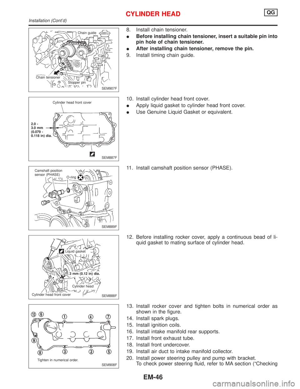
8. Install chain tensioner.
IBefore installing chain tensioner, insert a suitable pin into
pin hole of chain tensioner.
IAfter installing chain tensioner, remove the pin.
9. Install timing chain guide.
10. Install cylinder head front cover.
IApply liquid gasket to cylinder head front cover.
IUse Genuine Liquid Gasket or equivalent.
11. Install camshaft position sensor (PHASE).
12. Before installing rocker cover, apply a continuous bead of li-
quid gasket to mating surface of cylinder head.
13. Install rocker cover and tighten bolts in numerical order as
shown in the figure.
14. Install spark plugs.
15. Install ignition coils.
16. Install intake manifold rear supports.
17. Install front exhaust tube.
18. Install front undercover.
19. Install air duct to intake manifold collector.
20. Install power steering pulley and pump with bracket.
To check power steering fluid, refer to MA section (ªChecking
SEM907F Chain guide
Stopper pin Chain tensioner
SEM887F Cylinder head front cover
2.0 -
3.0 mm
(0.079 -
0.118 in) dia.
SEM889F Camshaft position
sensor (PHASE)
O-ring
SEM888F Liquid gasket
3 mm (0.12 in) dia.
Cylinder head
Cylinder head front cover
SEM908F Tighten in numerical order.
CYLINDER HEADQG
Installation (Cont'd)
EM-46
Page 1587 of 2267
Power Steering Fluid and Linesº, ªCHASSIS AND BODY
MAINTENANCEº).
21. Drive belts.
For adjusting drive belt deflection, refer to MA section (ªCheck-
ing Drive Beltsº, ªENGINE MAINTENANCEº).
22. Reinstall parts in reverse order of removal.
CYLINDER HEADQG
Installation (Cont'd)
EM-47
Page 1805 of 2267
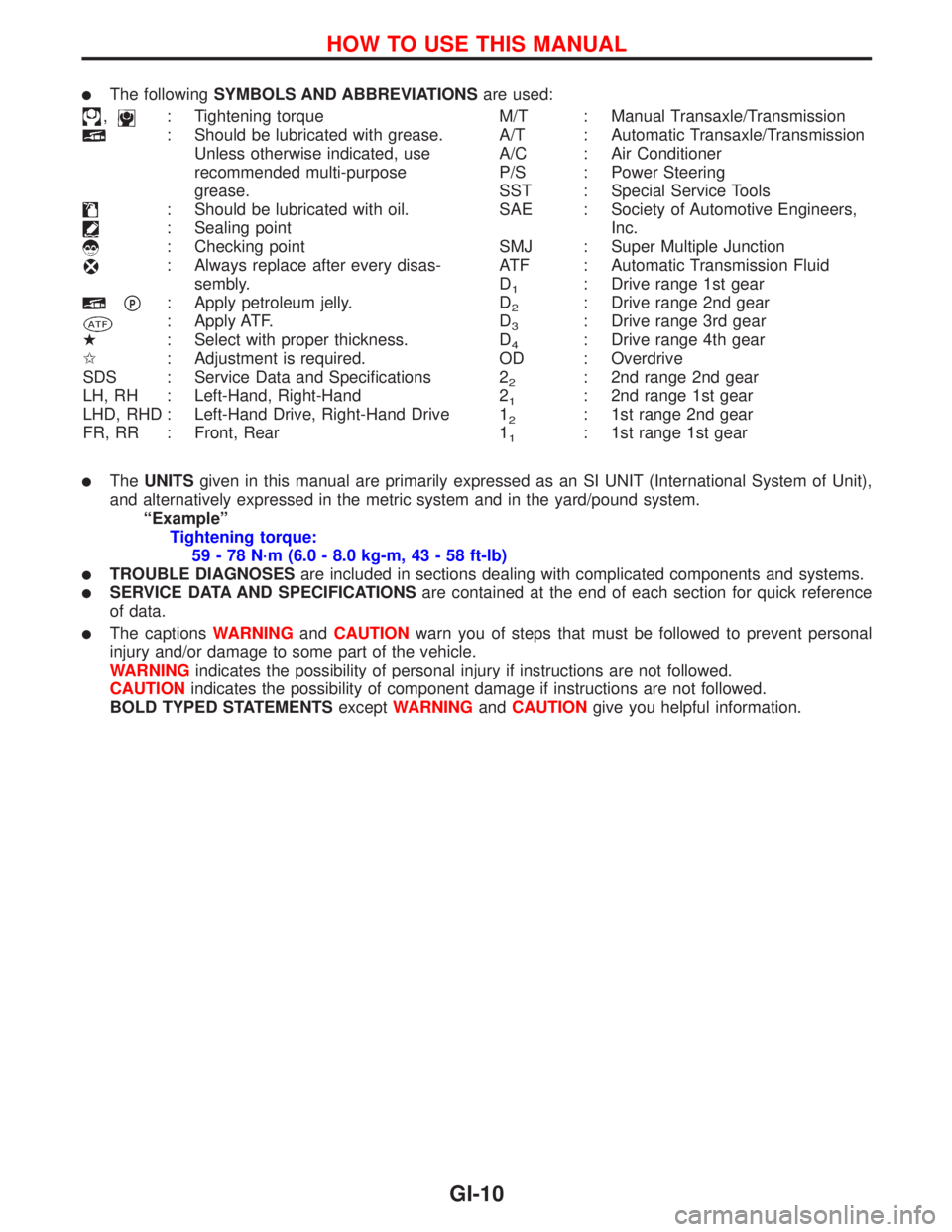
lThe followingSYMBOLS AND ABBREVIATIONSare used:
,: Tightening torque
: Should be lubricated with grease.
Unless otherwise indicated, use
recommended multi-purpose
grease.
: Should be lubricated with oil.
: Sealing point
: Checking point
: Always replace after every disas-
sembly.
pP: Apply petroleum jelly.
: Apply ATF.
H: Select with proper thickness.
I: Adjustment is required.
SDS : Service Data and Specifications
LH, RH : Left-Hand, Right-Hand
LHD, RHD : Left-Hand Drive, Right-Hand Drive
FR, RR : Front, RearM/T : Manual Transaxle/Transmission
A/T : Automatic Transaxle/Transmission
A/C : Air Conditioner
P/S : Power Steering
SST : Special Service Tools
SAE : Society of Automotive Engineers,
Inc.
SMJ : Super Multiple Junction
ATF : Automatic Transmission Fluid
D
1: Drive range 1st gear
D
2: Drive range 2nd gear
D
3: Drive range 3rd gear
D
4: Drive range 4th gear
OD : Overdrive
2
2: 2nd range 2nd gear
2
1: 2nd range 1st gear
1
2: 1st range 2nd gear
1
1: 1st range 1st gear
lTheUNITSgiven in this manual are primarily expressed as an SI UNIT (International System of Unit),
and alternatively expressed in the metric system and in the yard/pound system.
ªExampleº
Tightening torque:
59 - 78 N´m (6.0 - 8.0 kg-m, 43 - 58 ft-lb)
lTROUBLE DIAGNOSESare included in sections dealing with complicated components and systems.
lSERVICE DATA AND SPECIFICATIONSare contained at the end of each section for quick reference
of data.
lThe captionsWARNINGandCAUTIONwarn you of steps that must be followed to prevent personal
injury and/or damage to some part of the vehicle.
WARNINGindicates the possibility of personal injury if instructions are not followed.
CAUTIONindicates the possibility of component damage if instructions are not followed.
BOLD TYPED STATEMENTSexceptWARNINGandCAUTIONgive you helpful information.
HOW TO USE THIS MANUAL
GI-10
Page 1973 of 2267
O
Oil cooler (engine) ....................................LC-20, 30
Oil pan (engine) ...............................EM-17, 70, 129
Oil pressure (engine)............................LC-5, 16, 27
Oil pump (engine).................................LC-5, 17, 27
Oil pump regulator valve (engine) ....................LC-7
Oil seal replacement
(engine) ................................EM-29, 84, 138, 139
On board diagnostic
system ...............................EC-QG-36, EC-SR-48
Operational check (cool box) .........................HA-24
P
Park/Neutral position
switch.............................EC-QG-313, EC-SR-298
Park/neutral position switch (A/T) ...................AT-48
Parking brake control .....................................BR-48
Parking lamp .................................................EL-100
PCV (positive crankcase
ventilation) .........................EC-QG-28, EC-SR-30
PCV system inspection............................MA-26, 36
Periodic maintenance (for Europe) ..................MA-6
PGC/V - Wiring diagram ...EC-QG-264, EC-SR-252
PHASE - Wiring diagram .......................EC-QG-240
Pilot bushing replacement - See Pilot
converter ...................................................EM-117
Piston assembly..............EM-53, 60, 110, 117, 167,
175, 176, 185, 193, 199
Piston pin inspection.............EM-54, 110, 168, 171,
185, 193, 199
Piston ring inspection ....................EM-54, 111, 168,
185, 193, 199
Piston to bore clearance........................EM-56, 174
PNP/SW - Wiring
diagram..........................EC-QG-315, EC-SR-300
POWER - Wiring diagram...............................EL-12
Power door lock ....................................EL-245, 265
Power door mirror .........................................EL-231
Power seat ....................................................EL-233
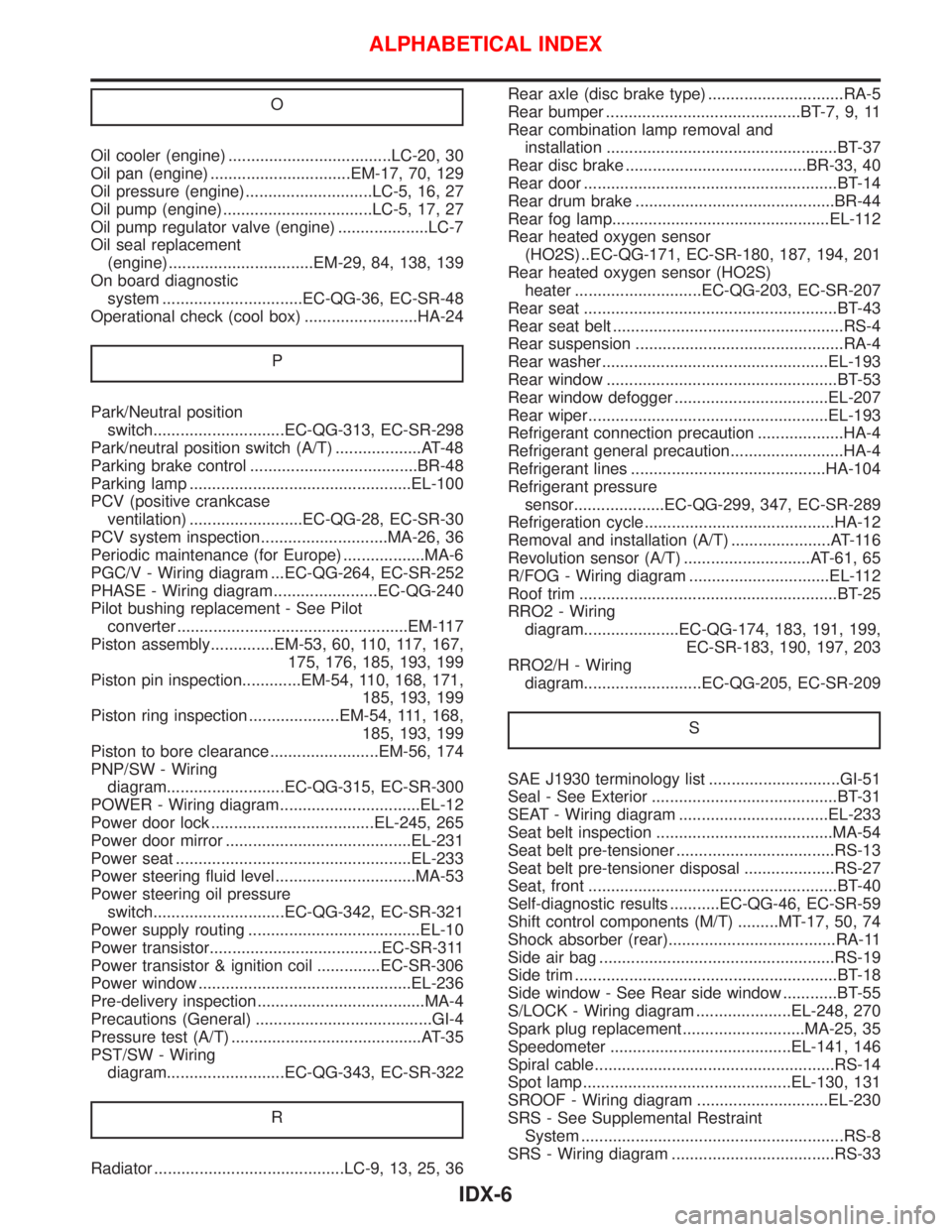
Power steering fluid level...............................MA-53
Power steering oil pressure
switch.............................EC-QG-342, EC-SR-321
Power supply routing ......................................EL-10
Power transistor......................................EC-SR-311
Power transistor & ignition coil ..............EC-SR-306
Power window ...............................................EL-236
Pre-delivery inspection.....................................MA-4
Precautions (General) .......................................GI-4
Pressure test (A/T) ..........................................AT-35
PST/SW - Wiring
diagram..........................EC-QG-343, EC-SR-322
R
Radiator ..........................................LC-9, 13, 25, 36Rear axle (disc brake type) ..............................RA-5
Rear bumper ...........................................BT-7, 9, 11
Rear combination lamp removal and
installation ...................................................BT-37
Rear disc brake ........................................BR-33, 40
Rear door ........................................................BT-14
Rear drum brake ............................................BR-44
Rear fog lamp................................................EL-112
Rear heated oxygen sensor
(HO2S) ..EC-QG-171, EC-SR-180, 187, 194, 201
Rear heated oxygen sensor (HO2S)
heater ............................EC-QG-203, EC-SR-207
Rear seat ........................................................BT-43
Rear seat belt ...................................................RS-4
Rear suspension ..............................................RA-4
Rear washer..................................................EL-193
Rear window ...................................................BT-53
Rear window defogger ..................................EL-207
Rear wiper.....................................................EL-193
Refrigerant connection precaution ...................HA-4
Refrigerant general precaution.........................HA-4
Refrigerant lines ...........................................HA-104
Refrigerant pressure
sensor....................EC-QG-299, 347, EC-SR-289
Refrigeration cycle..........................................HA-12
Removal and installation (A/T) ......................AT-116
Revolution sensor (A/T) ............................AT-61, 65
R/FOG - Wiring diagram ...............................EL-112
Roof trim .........................................................BT-25
RRO2 - Wiring
diagram.....................EC-QG-174, 183, 191, 199,
EC-SR-183, 190, 197, 203
RRO2/H - Wiring
diagram..........................EC-QG-205, EC-SR-209
S
SAE J1930 terminology list .............................GI-51
Seal - See Exterior .........................................BT-31
SEAT - Wiring diagram .................................EL-233
Seat belt inspection .......................................MA-54
Seat belt pre-tensioner ...................................RS-13
Seat belt pre-tensioner disposal ....................RS-27
Seat, front .......................................................BT-40
Self-diagnostic results ...........EC-QG-46, EC-SR-59
Shift control components (M/T) .........MT-17, 50, 74
Shock absorber (rear).....................................RA-11
Side air bag ....................................................RS-19
Side trim ..........................................................BT-18
Side window - See Rear side window ............BT-55
S/LOCK - Wiring diagram .....................EL-248, 270
Spark plug replacement...........................MA-25, 35
Speedometer ........................................EL-141, 146
Spiral cable.....................................................RS-14
Spot lamp..............................................EL-130, 131
SROOF - Wiring diagram .............................EL-230
SRS - See Supplemental Restraint
System ..........................................................RS-8
SRS - Wiring diagram ....................................RS-33
ALPHABETICAL INDEX
IDX-6
Page 2019 of 2267
Checking Cooling System ....................................... 42
Checking Fuel Lines ................................................ 43
Checking and Replacing Fuel Filter and Draining
Water ....................................................................... 43
Changing Air Cleaner Filter ..................................... 44
Changing Engine Oil................................................ 45
Changing Engine Oil Filter ...................................... 45
Checking Injection Nozzles ..................................... 46
Replacing Timing Belt .............................................. 47
CHASSIS AND BODY MAINTENANCE..................... 48
Checking Exhaust System....................................... 48
Checking Clutch Fluid Level and Leaks .................. 48
Checking Clutch System ......................................... 48
Checking M/T Oil ..................................................... 48
Changing M/T Oil..................................................... 49
Checking CVT Fluid Level ....................................... 49
Changing CVT Fluid ................................................ 50
Checking Brake Fluid Level and Leaks................... 51
Checking Brake System .......................................... 51
Changing Brake Fluid .............................................. 51
Checking Brake Booster, Vacuum Hoses,
Connections and Check Valve ................................ 51
Checking Disc Brake ............................................... 51
Balancing Wheels .................................................... 53Tire Rotation ............................................................ 53
Checking Steering Gear and Linkage ..................... 53
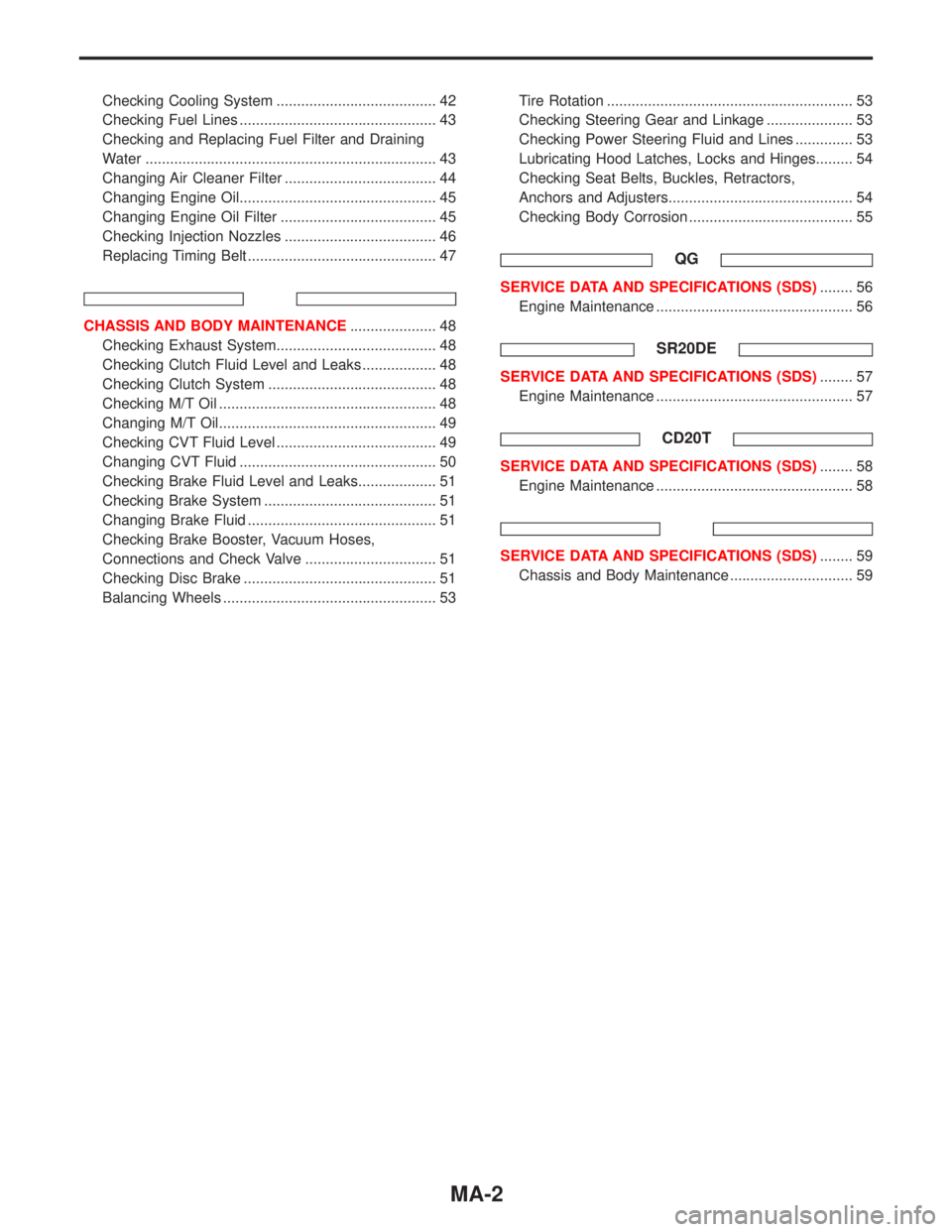
Checking Power Steering Fluid and Lines .............. 53
Lubricating Hood Latches, Locks and Hinges......... 54
Checking Seat Belts, Buckles, Retractors,
Anchors and Adjusters............................................. 54
Checking Body Corrosion ........................................ 55
QG
SERVICE DATA AND SPECIFICATIONS (SDS)........ 56
Engine Maintenance ................................................ 56
SR20DE
SERVICE DATA AND SPECIFICATIONS (SDS)........ 57
Engine Maintenance ................................................ 57
CD20T
SERVICE DATA AND SPECIFICATIONS (SDS)........ 58
Engine Maintenance ................................................ 58
SERVICE DATA AND SPECIFICATIONS (SDS)........ 59
Chassis and Body Maintenance .............................. 59
MA-2
Page 2021 of 2267
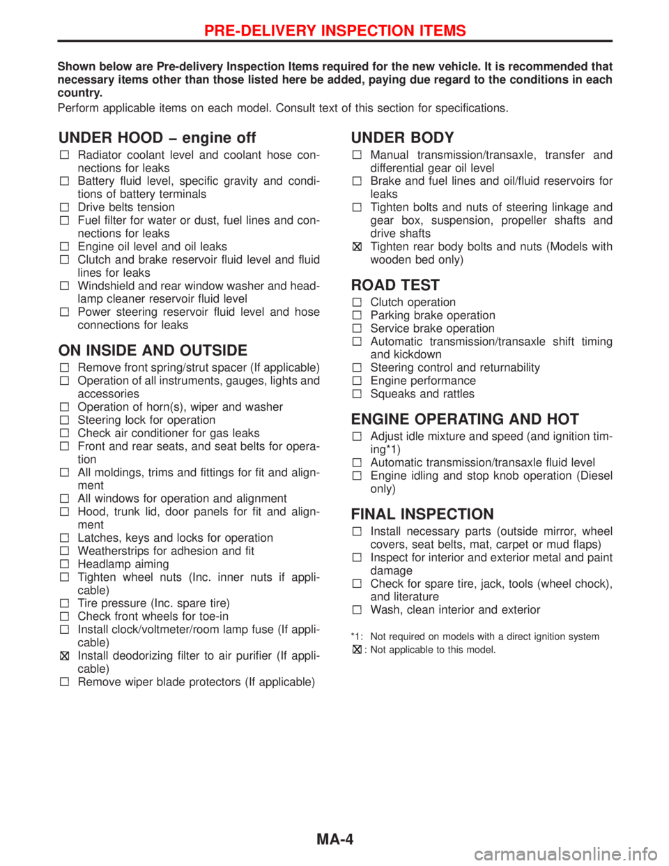
Shown below are Pre-delivery Inspection Items required for the new vehicle. It is recommended that
necessary items other than those listed here be added, paying due regard to the conditions in each
country.
Perform applicable items on each model. Consult text of this section for specifications.
UNDER HOOD � engine off
Radiator coolant level and coolant hose con-
nections for leaks
Battery fluid level, specific gravity and condi-
tions of battery terminals
Drive belts tension
Fuel filter for water or dust, fuel lines and con-
nections for leaks
Engine oil level and oil leaks
Clutch and brake reservoir fluid level and fluid
lines for leaks
Windshield and rear window washer and head-
lamp cleaner reservoir fluid level
Power steering reservoir fluid level and hose
connections for leaks
ON INSIDE AND OUTSIDE
Remove front spring/strut spacer (If applicable)
Operation of all instruments, gauges, lights and
accessories
Operation of horn(s), wiper and washer
Steering lock for operation
Check air conditioner for gas leaks
Front and rear seats, and seat belts for opera-
tion
All moldings, trims and fittings for fit and align-
ment
All windows for operation and alignment
Hood, trunk lid, door panels for fit and align-
ment
Latches, keys and locks for operation
Weatherstrips for adhesion and fit
Headlamp aiming
Tighten wheel nuts (Inc. inner nuts if appli-
cable)
Tire pressure (Inc. spare tire)
Check front wheels for toe-in
Install clock/voltmeter/room lamp fuse (If appli-
cable)
Install deodorizing filter to air purifier (If appli-
cable)
Remove wiper blade protectors (If applicable)
UNDER BODY
Manual transmission/transaxle, transfer and
differential gear oil level
Brake and fuel lines and oil/fluid reservoirs for
leaks
Tighten bolts and nuts of steering linkage and
gear box, suspension, propeller shafts and
drive shafts
Tighten rear body bolts and nuts (Models with
wooden bed only)
ROAD TEST
Clutch operation
Parking brake operation
Service brake operation
Automatic transmission/transaxle shift timing
and kickdown
Steering control and returnability
Engine performance
Squeaks and rattles
ENGINE OPERATING AND HOT
Adjust idle mixture and speed (and ignition tim-
ing*1)
Automatic transmission/transaxle fluid level
Engine idling and stop knob operation (Diesel
only)
FINAL INSPECTION
Install necessary parts (outside mirror, wheel
covers, seat belts, mat, carpet or mud flaps)
Inspect for interior and exterior metal and paint
damage
Check for spare tire, jack, tools (wheel chock),
and literature
Wash, clean interior and exterior
*1: Not required on models with a direct ignition system
: Not applicable to this model.
PRE-DELIVERY INSPECTION ITEMS
MA-4