1999 NISSAN PRIMERA seat adjustment
[x] Cancel search: seat adjustmentPage 123 of 2267
BRAKE SYSTEM
SECTION
BR
CONTENTS
PRECAUTIONS............................................................. 3
Supplemental Restraint System (SRS)²AIR
BAG²and²SEAT BELT PRE-TENSIONER²............. 3
Precautions for Brake System ................................... 3
Precautions When Working On ABS ......................... 4
Wiring Diagrams and Trouble Diagnosis ................... 4
PRECAUTIONS AND PREPARATION.......................... 5
Commercial Service Tools ......................................... 5
NOISE, VIBRATION AND HARSHNESS (NVH)
TROUBLE SHOOTING.................................................. 6
NVH Troubleshooting Chart....................................... 6
CHECK AND ADJUSTMENT........................................ 7
Checking Brake Fluid Level....................................... 7
Checking Brake Line ................................................. 7
Changing Brake Fluid ................................................ 7
Brake Burnishing Procedure...................................... 7
Bleeding Brake System ............................................. 8
BRAKE HYDRAULIC LINE........................................... 9
Removal ................................................................... 10
Inspection................................................................. 10
Installation ................................................................ 10
CONTROL VALVE........................................................ 11
Dual Proportioning Valve .......................................... 11
BRAKE PEDAL AND BRACKET................................ 13
Removal and Installation ......................................... 13
Inspection................................................................. 13
Adjustment ............................................................... 13
MASTER CYLINDER................................................... 15
Removal ................................................................... 15
Disassembly............................................................. 15
Inspection................................................................. 16
Assembly ................................................................. 16
Installation ................................................................ 17BRAKE BOOSTER...................................................... 18
On-vehicle Service................................................... 18
Removal ................................................................... 18
Inspection................................................................. 19
Installation ................................................................ 19
VACUUM HOSE........................................................... 20
Removal and Installation ......................................... 21
Inspection................................................................. 21
FRONT DISC BRAKE................................................. 23
Pad Replacement .................................................... 23
Removal ................................................................... 24
Disassembly............................................................. 25
Inspection - Caliper.................................................. 25
SR20DE - M/T
FRONT DISC BRAKE................................................. 26
Pad Replacement .................................................... 26
Installation ................................................................ 28
Removal ................................................................... 29
Disassembly............................................................. 29
Inspection - Caliper.................................................. 29
FRONT DISC BRAKE................................................. 31
Inspection - Rotor .................................................... 31
Assembly ................................................................. 31
Installation ................................................................ 32
REAR DISC BRAKE TYPE 1...................................... 33
Component .............................................................. 33
Pad Replacement .................................................... 33
Removal ................................................................... 35
Disassembly............................................................. 35
BR
Page 125 of 2267
Supplemental Restraint System (SRS) ªAIR
BAGº and ªSEAT BELT PRE-TENSIONERº
The Supplemental Restraint System such as ªAIR BAGº and ªSEAT BELT PRE-TENSIONERº used along
with a seat belt, helps to reduce the risk or severity of injury to the driver and front passenger for certain
types of collision. The SRS system composition which is available to NISSAN MODEL P11 is as follows (The
composition varies according to the destination and optional equipment.):
lFor a frontal collision
The Supplemental Restraint System consists of driver air bag module (located in the center of the
steering wheel), front passenger air bag module (located on the instrument panel on passenger side),
front seat belt pre-tensioners, a diagnosis sensor unit, warning lamp, wiring harness and spiral cable.
lFor a side collision
The Supplemental Restraint System consists of front side air bag module (located in the outer side of
front seat), side air bag (satellite) sensor, diagnosis sensor unit (one of components of air bags for a
frontal collision), wiring harness, warning lamp (one of components of air bags for a frontal collision).
Information necessary to service the system safely is included in theRS sectionof this Service Manual.
WARNING:
lTo avoid rendering the SRS inoperative, which could increase the risk of personal injury or death
in the event of a collision which would result in air bag inflation, all maintenance should be per-
formed by an authorized NISSAN dealer.
lImproper maintenance, including incorrect removal and installation of the SRS, can lead to per-
sonal injury caused by unintentional activation of the system. For removal of Spiral Cable and
Air Bag Module, see the RS section.
lDo not use electrical test equipment on any circuit related to the SRS unless instructed to in this
Service Manual. Spiral cable and wiring harnesses covered with yellow insulation tape either just
before the harness connectors or for the complete harness are related to the SRS.
Precautions for Brake System
lRecommended fluid is brake fluid ªDOT 4º.
lNever reuse drained brake fluid.
lBe careful not to splash brake fluid on painted areas.
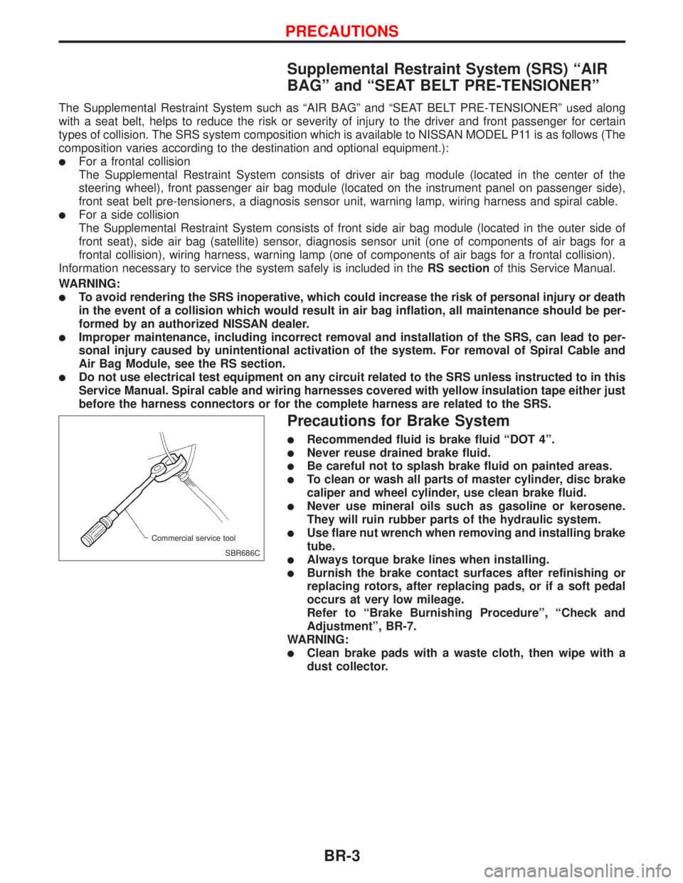
lTo clean or wash all parts of master cylinder, disc brake
caliper and wheel cylinder, use clean brake fluid.
lNever use mineral oils such as gasoline or kerosene.
They will ruin rubber parts of the hydraulic system.
lUse flare nut wrench when removing and installing brake
tube.
lAlways torque brake lines when installing.
lBurnish the brake contact surfaces after refinishing or
replacing rotors, after replacing pads, or if a soft pedal
occurs at very low mileage.
Refer to ªBrake Burnishing Procedureº, ªCheck and
Adjustmentº, BR-7.
WARNING:
lClean brake pads with a waste cloth, then wipe with a
dust collector.
SBR686C Commercial service tool
PRECAUTIONS
BR-3
Page 232 of 2267
Side and Floor Trim
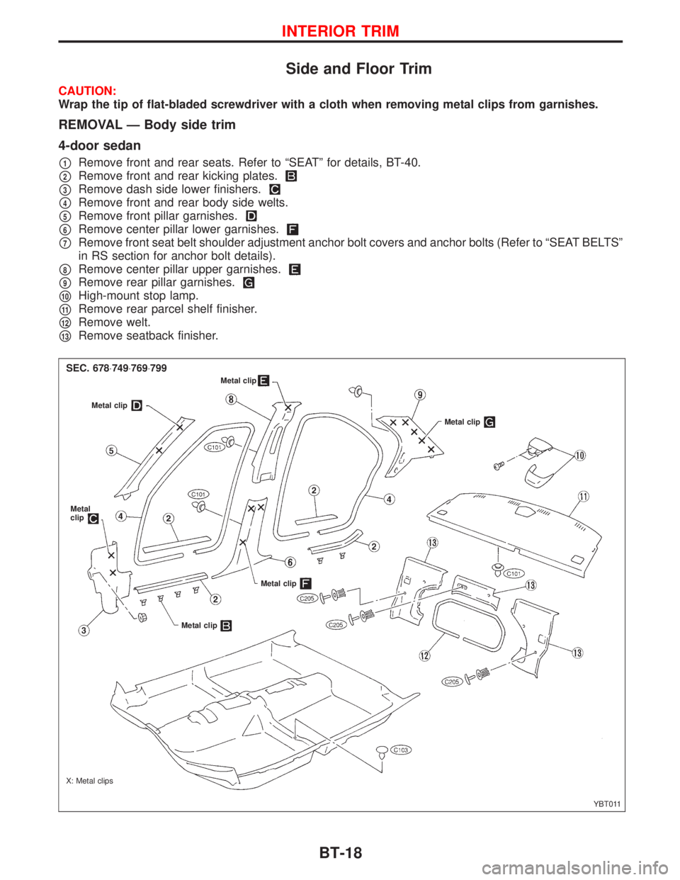
CAUTION:
Wrap the tip of flat-bladed screwdriver with a cloth when removing metal clips from garnishes.
REMOVAL Ð Body side trim
4-door sedan
p1Remove front and rear seats. Refer to ªSEATº for details, BT-40.
p2Remove front and rear kicking plates.
p3Remove dash side lower finishers.
p4Remove front and rear body side welts.
p5Remove front pillar garnishes.
p6Remove center pillar lower garnishes.
p7Remove front seat belt shoulder adjustment anchor bolt covers and anchor bolts (Refer to ªSEAT BELTSº
in RS section for anchor bolt details).
p8Remove center pillar upper garnishes.
p9Remove rear pillar garnishes.
p10High-mount stop lamp.
p11Remove rear parcel shelf finisher.
p12Remove welt.
p13Remove seatback finisher.
YBT011 X: Metal clipsMetal clip
Metal clip
Metal clip
Metal
clip
Metal clip
Metal clip
SEC. 678×749×769×799
INTERIOR TRIM
BT-18
Page 234 of 2267
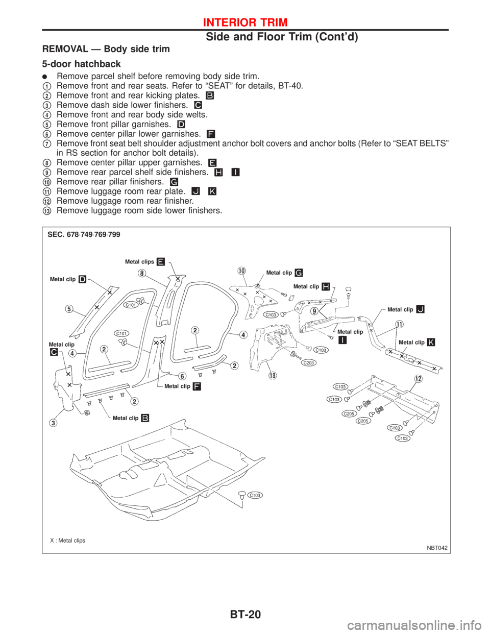
REMOVAL Ð Body side trim
5-door hatchback
lRemove parcel shelf before removing body side trim.
p1Remove front and rear seats. Refer to ªSEATº for details, BT-40.
p2Remove front and rear kicking plates.
p3Remove dash side lower finishers.
p4Remove front and rear body side welts.
p5Remove front pillar garnishes.
p6Remove center pillar lower garnishes.
p7Remove front seat belt shoulder adjustment anchor bolt covers and anchor bolts (Refer to ªSEAT BELTSº
in RS section for anchor bolt details).
p8Remove center pillar upper garnishes.
p9Remove rear parcel shelf side finishers.
p10Remove rear pillar finishers.
p11Remove luggage room rear plate.
p12Remove luggage room rear finisher.
p13Remove luggage room side lower finishers.
NBT042 Metal clip
Metal clips
Metal clip
Metal clip
Metal clip
Metal clip
Metal clip
Metal clip
Metal clip
SEC. 678×749×769×799
Metal clip
X : Metal clips
INTERIOR TRIM
Side and Floor Trim (Cont'd)
BT-20
Page 236 of 2267
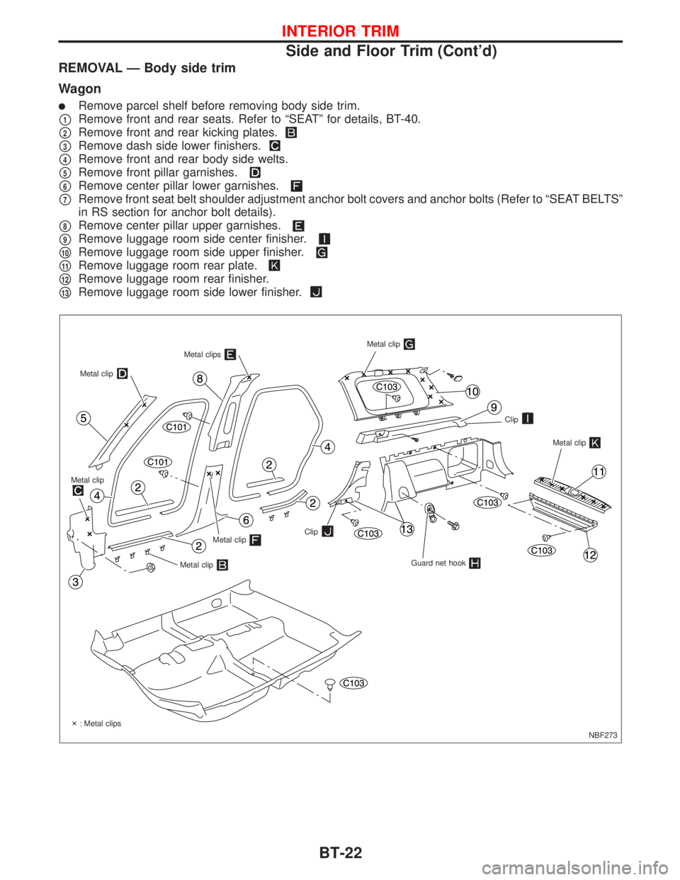
REMOVAL Ð Body side trim
Wagon
lRemove parcel shelf before removing body side trim.
p1Remove front and rear seats. Refer to ªSEATº for details, BT-40.
p2Remove front and rear kicking plates.
p3Remove dash side lower finishers.
p4Remove front and rear body side welts.
p5Remove front pillar garnishes.
p6Remove center pillar lower garnishes.
p7Remove front seat belt shoulder adjustment anchor bolt covers and anchor bolts (Refer to ªSEAT BELTSº
in RS section for anchor bolt details).
p8Remove center pillar upper garnishes.
p9Remove luggage room side center finisher.
p10Remove luggage room side upper finisher.
p11Remove luggage room rear plate.
p12Remove luggage room rear finisher.
p13Remove luggage room side lower finisher.
NBF273 Metal clip
Metal clipsMetal clip
Guard net hook
Metal clip
Metal clip
Metal clip
Metal clip
Clip
.
Clip
: Metal clips
INTERIOR TRIM
Side and Floor Trim (Cont'd)
BT-22
Page 295 of 2267
ENGINE CONTROL SYSTEM
SECTION
EC
CONTENTS
CD20T
PRECAUTIONS AND PREPARATION.......................... 3
Special Service Tools ................................................ 3
Engine Fuel & Emission Control System .................. 5
Supplemental Restraint System (SRS)²AIR
BAG²and²SEAT BELT PRE-TENSIONER²............. 6
Precautions for On Board Diagnostic (OBD)
System of Engine ...................................................... 6
Precautions ................................................................ 7
ENGINE AND EMISSION CONTROL OVERALL
SYSTEM......................................................................... 9
Engine Control Module Component Parts
Location ..................................................................... 9
Circuit Diagram ......................................................... 11
System Diagram ...................................................... 12
Vacuum Hose Drawing ............................................ 13
System Chart ........................................................... 14
ENGINE AND EMISSION BASIC CONTROL
SYSTEM DESCRIPTION............................................. 15
Glow Control System ............................................... 15
Fuel Injection System .............................................. 15
Fuel Injection Timing System .................................. 18
Air Conditioning Cut Control .................................... 20
Cooling Fan Control................................................. 20
CRANKCASE VENTILATION SYSTEM...................... 21
Description ............................................................... 21
Blow-by Control Valve ............................................. 21
Ventilation Hose ....................................................... 21
INJECTION NOZZLE................................................... 22
Removal and Installation ......................................... 22
Test and Adjustment ................................................ 22
ELECTRONIC FUEL INJECTION PUMP.................... 24
Removal ................................................................... 24
Installation ................................................................ 25Disassembly and Assembly ..................................... 26
ON BOARD DIAGNOSTIC SYSTEM
DESCRIPTION............................................................. 27
CONSULT-II ............................................................. 27
TROUBLE DIAGNOSIS - INTRODUCTION................ 33
Introduction .............................................................. 33
Diagnostic Worksheet .............................................. 34
TROUBLE DIAGNOSIS - WORK FLOW.................... 35
Work Flow ................................................................ 35
Description for Work Flow ....................................... 36
TROUBLE DIAGNOSIS - BASIC INSPECTION......... 37
Basic Inspection....................................................... 37
TROUBLE DIAGNOSIS - GENERAL
DESCRIPTION............................................................. 39
Diagnostic Trouble Chart ......................................... 39
Symptom Matrix Chart ............................................. 47
CONSULT-II Reference Value in Data Monitor
Mode ........................................................................ 50
Major Sensor Reference Graph in Data Monitor
Mode ........................................................................ 51
ECM Terminals and Reference Value ..................... 52
TROUBLE DIAGNOSIS FOR POWER SUPPLY........ 59
Main Power Supply and Ground Circuit .................. 59
TROUBLE DIAGNOSIS 1............................................ 62
Mass Air Flow Sensor (MAFS) ................................ 62
TROUBLE DIAGNOSIS 2............................................ 66
Engine Coolant Temperature (ECT) Sensor ........... 66
TROUBLE DIAGNOSIS 3............................................ 70
Vehicle Speed Sensor (VSS) .................................. 70
TROUBLE DIAGNOSIS 4............................................ 74
Control Sleeve Position Sensor (CSPS) ................. 74
TROUBLE DIAGNOSIS 5............................................ 78
Electric Governor ..................................................... 78
TROUBLE DIAGNOSIS 6............................................ 82
EC
Page 443 of 2267
ENGINE CONTROL SYSTEM
SECTION
EC
CONTENTS
QG16I18DE
TROUBLE DIAGNOSIS - INDEX....................................6
Alphabetical & P No. Index for DTC ...........................6
PRECAUTIONS...............................................................9
Supplemental Restraint System (SRS)²AIR
BAG²and²SEAT BELT PRE-TENSIONER²...............9
Precautions for On Board Diagnostic (OBD)
System of Engine ........................................................9
Engine Fuel & Emission Control System ..................10
Precautions ................................................................ 11
Wiring Diagrams and Trouble Diagnosis ...................12
PREPARATION..............................................................13
Special Service Tools ................................................13
Commercial Service Tool ...........................................13
ENGINE AND EMISSION CONTROL OVERALL
SYSTEM.........................................................................14
Engine Control Component Parts Location ...............14
Circuit Diagram ..........................................................17
System Diagram ........................................................18
Vacuum Hose Drawing ..............................................19
System Chart .............................................................20
ENGINE AND EMISSION BASIC CONTROL
SYSTEM DESCRIPTION...............................................21
Multiport Fuel Injection (MFI) System .......................21
Electronic Ignition (EI) System ..................................23
Air Conditioning Cut Control ......................................24
Fuel Cut Control (at no load & high engine
speed) ........................................................................25
Evaporative Emission System ...................................25
Positive Crankcase Ventilation ..................................28
BASIC SERVICE PROCEDURE...................................29
Fuel Pressure Release ..............................................29
Fuel Pressure Check .................................................29
Fuel Pressure Regulator Check ................................30
Injector .......................................................................30
Idle Speed/Ignition Timing/Idle Mixture Ratio
Adjustment .................................................................32Idle Air Volume Learning ...........................................33
ON BOARD DIAGNOSTIC SYSTEM
DESCRIPTION...............................................................36
Introduction ................................................................36
Two Trip Detection Logic ...........................................36
Emission-related Diagnostic Information ...................37
Malfunction Indicator (MI) ..........................................45
OBD System Operation Chart ...................................50
CONSULT-II ...............................................................55
Generic Scan Tool (GST) ..........................................66
TROUBLE DIAGNOSIS - INTRODUCTION..................68
Introduction ................................................................68
Work Flow ..................................................................70
TROUBLE DIAGNOSIS - BASIC INSPECTION...........72
Basic Inspection.........................................................72
TROUBLE DIAGNOSIS - GENERAL
DESCRIPTION...............................................................80
DTC Inspection Priority Chart....................................80
Fail-safe Chart ...........................................................81
Symptom Matrix Chart ...............................................82
CONSULT-II Reference Value in Data Monitor
Mode ..........................................................................86
Major Sensor Reference Graph in Data Monitor
Mode ..........................................................................88
ECM Terminals and Reference Value .......................91
TROUBLE DIAGNOSIS - SPECIFICATION VALUE....98
Description .................................................................98
Testing Condition .......................................................98
Inspection Procedure .................................................98
Diagnostic Procedure ................................................99
TROUBLE DIAGNOSIS FOR INTERMITTENT
INCIDENT.....................................................................102
Description ...............................................................102
Diagnostic Procedure ..............................................102
TROUBLE DIAGNOSIS FOR POWER SUPPLY........103
Main Power Supply and Ground Circuit ..................103
EC
Page 801 of 2267
ENGINE CONTROL SYSTEM
SECTION
EC
CONTENTS
SR20DE
TROUBLE DIAGNOSIS - INDEX....................................6
Alphabetical & P No. Index for DTC ...........................6
PRECAUTIONS.............................................................10
Supplemental Restraint System (SRS)²AIR
BAG²and²SEAT BELT PRE-TENSIONER².............10
Precautions for On Board Diagnostic (OBD)
System of Engine and CVT .......................................10
Engine Fuel & Emission Control System .................. 11
Precautions ................................................................12
Wiring Diagrams and Trouble Diagnosis ...................13
PREPARATION.............................................................14
Special Service Tools ................................................14
Commercial Service Tool ...........................................14
ENGINE AND EMISSION CONTROL OVERALL
SYSTEM.........................................................................15
Engine Control Component Parts Location ...............15
Circuit Diagram ..........................................................19
System Diagram ........................................................20
Vacuum Hose Drawing ..............................................21
System Chart .............................................................22
ENGINE AND EMISSION BASIC CONTROL
SYSTEM DESCRIPTION...............................................23
Multiport Fuel Injection (MFI) System .......................23
Distributor Ignition (DI) System .................................25
Air Conditioning Cut Control ......................................26
Fuel Cut Control (at no load & high engine
speed) ........................................................................27
Evaporative Emission System ...................................27
Positive Crankcase Ventilation ..................................30
BASIC SERVICE PROCEDURE...................................31
Fuel Pressure Release ..............................................31
Fuel Pressure Check .................................................31
Fuel Pressure Regulator Check ................................32
Injector .......................................................................32
Idle Speed/Ignition Timing/Idle Mixture Ratio
Adjustment .................................................................34Idle Air Volume Learning ...........................................46
ON BOARD DIAGNOSTIC SYSTEM
DESCRIPTION...............................................................48
Introduction ................................................................48
Two Trip Detection Logic ...........................................48
Emission-related Diagnostic Information ...................49
Malfunction Indicator (MI) ..........................................58
OBD System Operation Chart ...................................63
CONSULT-II ...............................................................68
Generic Scan Tool (GST) ..........................................78
TROUBLE DIAGNOSIS - INTRODUCTION..................80
Introduction ................................................................80
Work Flow ..................................................................82
TROUBLE DIAGNOSIS - BASIC INSPECTION...........84
Basic Inspection.........................................................84
TROUBLE DIAGNOSIS - GENERAL
DESCRIPTION...............................................................92
DTC Inspection Priority Chart....................................92
Fail-safe Chart ...........................................................93
Symptom Matrix Chart ...............................................94
CONSULT-II Reference Value in Data Monitor
Mode ..........................................................................98
Major Sensor Reference Graph in Data Monitor
Mode ........................................................................100
ECM Terminals and Reference Value .....................103
TROUBLE DIAGNOSIS - SPECIFICATION VALUE.. 110
Description ............................................................... 110
Testing Condition ..................................................... 110
Inspection Procedure ............................................... 110
Diagnostic Procedure .............................................. 111
TROUBLE DIAGNOSIS FOR INTERMITTENT
INCIDENT..................................................................... 114
Description ............................................................... 114
Diagnostic Procedure .............................................. 114
TROUBLE DIAGNOSIS FOR POWER SUPPLY........ 115
Main Power Supply and Ground Circuit .................. 115
EC