1999 NISSAN PRIMERA oil filter
[x] Cancel search: oil filterPage 137 of 2267
Removal
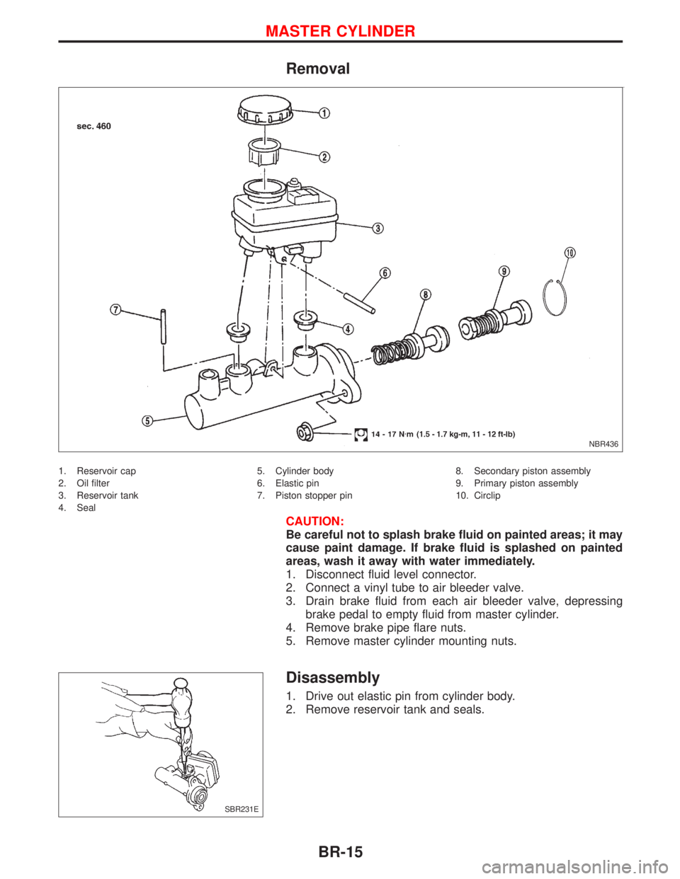
1. Reservoir cap
2. Oil filter
3. Reservoir tank
4. Seal5. Cylinder body
6. Elastic pin
7. Piston stopper pin8. Secondary piston assembly
9. Primary piston assembly
10. Circlip
CAUTION:
Be careful not to splash brake fluid on painted areas; it may
cause paint damage. If brake fluid is splashed on painted
areas, wash it away with water immediately.
1. Disconnect fluid level connector.
2. Connect a vinyl tube to air bleeder valve.
3. Drain brake fluid from each air bleeder valve, depressing
brake pedal to empty fluid from master cylinder.
4. Remove brake pipe flare nuts.
5. Remove master cylinder mounting nuts.
Disassembly
1. Drive out elastic pin from cylinder body.
2. Remove reservoir tank and seals.
NBR436
SBR231E
MASTER CYLINDER
BR-15
Page 527 of 2267
SYMPTOM
Reference
page
HARD/NO START/RESTART (EXCP. HA)
ENGINE STALL
HESITATION/SURGING/FLAT SPOT
SPARK KNOCK/DETONATION
LACK OF POWER/POOR ACCELERATION
HIGH IDLE/LOW IDLE
ROUGH IDLE/HUNTING
IDLING VIBRATION
SLOW/NO RETURN TO IDLE
OVERHEATS/WATER TEMPERATURE HIGH
EXCESSIVE FUEL CONSUMPTION
EXCESSIVE OIL CONSUMPTION
BATTERY DEAD (UNDER CHARGE)
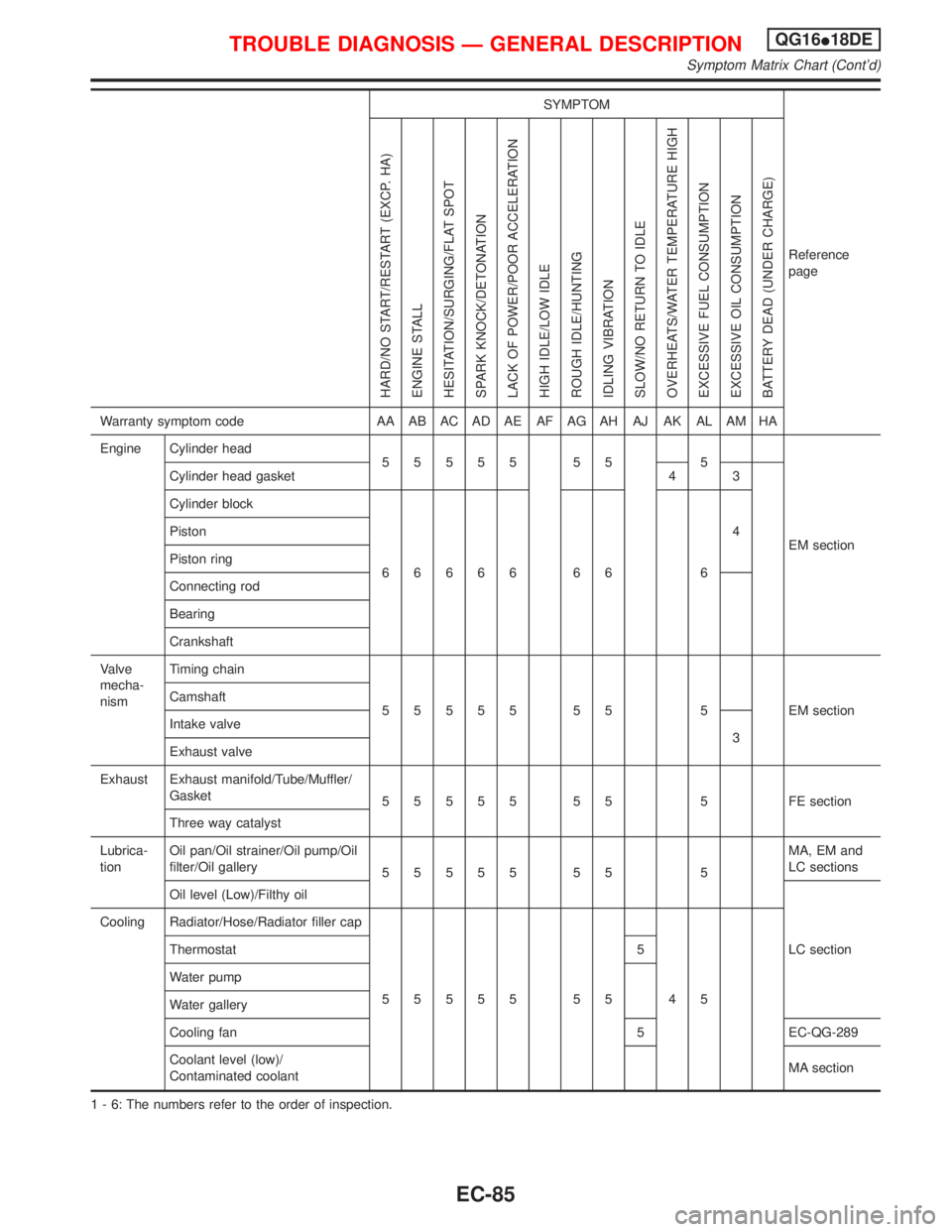
Warranty symptom code AA AB AC AD AE AF AG AH AJ AK AL AM HA
Engine Cylinder head
55555 55 5
EM section Cylinder head gasket 4 3
Cylinder block
66666 66 64 Piston
Piston ring
Connecting rod
Bearing
Crankshaft
Valve
mecha-
nismTiming chain
55555 55 5 EMsection Camshaft
Intake valve
3
Exhaust valve
Exhaust Exhaust manifold/Tube/Muffler/
Gasket
55555 55 5 FEsection
Three way catalyst
Lubrica-
tionOil pan/Oil strainer/Oil pump/Oil
filter/Oil gallery
55555 55 5MA, EM and
LC sections
Oil level (Low)/Filthy oil
LC section Cooling Radiator/Hose/Radiator filler cap
55555 55 45 Thermostat 5
Water pump
Water gallery
Cooling fan 5 EC-QG-289
Coolant level (low)/
Contaminated coolantMA section
1 - 6: The numbers refer to the order of inspection.
TROUBLE DIAGNOSIS Ð GENERAL DESCRIPTIONQG16I18DE
Symptom Matrix Chart (Cont'd)
EC-85
Page 672 of 2267
Diagnostic ProcedureNCEC0211
1 RETIGHTEN GROUND SCREWS
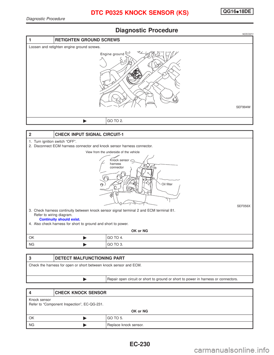
Loosen and retighten engine ground screws.
SEF994W
©GO TO 2.
2 CHECK INPUT SIGNAL CIRCUIT-1
1. Turn ignition switch ªOFFº.
2. Disconnect ECM harness connector and knock sensor harness connector.
SEF056X3. Check harness continuity between knock sensor signal terminal 2 and ECM terminal 81.
Refer to wiring diagram.
Continuity should exist.
4. Also check harness for short to ground and short to power.
OK or NG
OK©GO TO 4.
NG©GO TO 3.
3 DETECT MALFUNCTIONING PART
Check the harness for open or short between knock sensor and ECM.
©Repair open circuit or short to ground or short to power in harness or connectors.
4 CHECK KNOCK SENSOR
Knock sensor
Refer to ªComponent Inspectionº, EC-QG-231.
OK or NG
OK©GO TO 5.
NG©Replace knock sensor.
View from the underside of the vehicle
Knock sensor
harness
connector
Oil filter
DTC P0325 KNOCK SENSOR (KS)QG16I18DE
Diagnostic Procedure
EC-230
Page 897 of 2267
SYMPTOM
Reference
page
HARD/NO START/RESTART (EXCP. HA)
ENGINE STALL
HESITATION/SURGING/FLAT SPOT
SPARK KNOCK/DETONATION
LACK OF POWER/POOR ACCELERATION
HIGH IDLE/LOW IDLE
ROUGH IDLE/HUNTING
IDLING VIBRATION
SLOW/NO RETURN TO IDLE
OVERHEATS/WATER TEMPERATURE HIGH
EXCESSIVE FUEL CONSUMPTION
EXCESSIVE OIL CONSUMPTION
BATTERY DEAD (UNDER CHARGE)
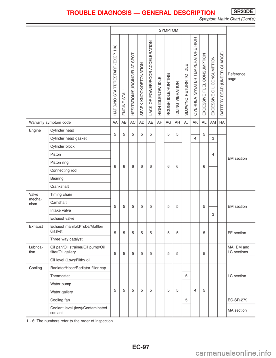
Warranty symptom code AA AB AC AD AE AF AG AH AJ AK AL AM HA
Engine Cylinder head
55555 55 5
EM section Cylinder head gasket 4 3
Cylinder block
66666 66 64 Piston
Piston ring
Connecting rod
Bearing
Crankshaft
Valve
mecha-
nismTiming chain
55555 55 5 EMsection Camshaft
Intake valve
3
Exhaust valve
Exhaust Exhaust manifold/Tube/Muffler/
Gasket
55555 55 5 FEsection
Three way catalyst
Lubrica-
tionOil pan/Oil strainer/Oil pump/Oil
filter/Oil gallery
55555 55 5MA, EM and
LC sections
Oil level (Low)/Filthy oil
LC section Cooling Radiator/Hose/Radiator filler cap
55555 55 45 Thermostat 5
Water pump
Water gallery
Cooling fan 5 EC-SR-279
Coolant level (low)/Contaminated
coolantMA section
1 - 6: The numbers refer to the order of inspection.
TROUBLE DIAGNOSIS Ð GENERAL DESCRIPTIONSR20DE
Symptom Matrix Chart (Cont'd)
EC-97
Page 1553 of 2267
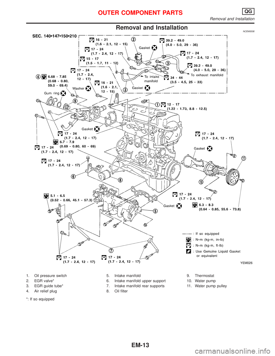
Removal and InstallationNCEM0006
1. Oil pressure switch
2. EGR valve*
3. EGR guide tube*
4. Air relief plug5. Intake manifold
6. Intake manifold upper support
7. Intake manifold rear supports
8. Oil filter9. Thermostat
10. Water pump
11. Water pump pulley
*: If so equipped
YEM026
OUTER COMPONENT PARTSQG
Removal and Installation
EM-13
Page 1606 of 2267
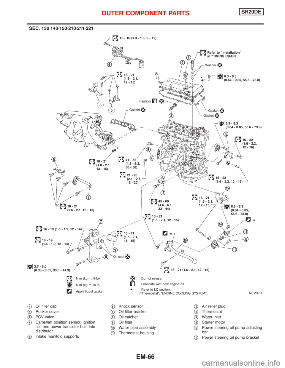
p1Oil filler cap
p2Rocker cover
p3PCV valve
p4Camshaft position sensor, ignition
coil and power transistor built into
distributor
p5Intake manifold supports
p6Knock sensor
p7Oil filter bracket
p8Oil catcher
p9Oil filter
p10Water pipe assembly
p11Thermostat housing
p12Air relief plug
p13Thermostat
p14Water inlet
p15Starter motor
p16Power steering oil pump adjusting
bar
p17Power steering oil pump bracket
NEM373
SEC. 130×140×150×210×211×221
.41-52
(4.2 - 5.3,
30 - 38)Insulator
21-26
(2.1 - 2.7,
15 - 20)
18-21
(1.8 - 2.1,
13 - 15)
16-21
(1.6 - 2.1, 12 - 15)
45-60
(4.6 - 6.1,
33 - 44)
16-21
(1.6 - 2.1, 12 - 15)
16 - 19 (1.6 - 1.9, 12 - 14)Gasket
13 - 16 (1.3 - 1.6, 9 - 12)
Gasket
Gasket
Washer
6.3 - 8.3
(0.64 - 0.85, 55.6 - 73.8)
Refer to ªInstallationº
in ªTIMING CHAINº.
6.3 - 8.3
(0.64 - 0.85, 55.6 - 73.8)
16-22
(1.6 - 2.2,
12 - 16)
.16-22
(1.6 - 2.2, 12 - 16)
16-21
(1.6 - 2.1,
12 - 15)
6.3 - 8.3
(0.64 - 0.85,
55.6 - 73.8)
16 - 21 (1.6 - 2.1, 12 - 15)
16-19
(1.6 - 1.9, 12 - 14)
15-21
(1.5 - 2.1,
11 - 15)
3.7 - 5.0
(0.38 - 0.51, 33.0 - 44.3)
N´m (kg-m, ft-lb)
N´m (kg-m, in-lb)
Apply liquid gasket.Oil seal
: Do not re-use.
: Lubricate with new engine oil.
: Refer to LC section.
(ªThermostatº, ªENGINE COOLING SYSTEMº).
H
H
H
16-21
(1.6 - 2.1,
12 - 15)
OUTER COMPONENT PARTSSR20DE
EM-66
Page 1802 of 2267
lWear protective clothing, including impervious gloves where
practicable.
lDo not put oily rags in pockets.
lAvoid contaminating clothes, particularly underpants, with oil.
lHeavily soiled clothing and oil-impregnated footwear should
not be worn. Overalls must be cleaned regularly.
lFirst Aid treatment should be obtained immediately for open
cuts and wounds.
lUse barrier creams, applying them before each work period,
to help the removal of oil from the skin.
lWash with soap and water to ensure all oil is removed (skin
cleansers and nail brushes will help). Preparations contain-
ing lanolin replace the natural skin oils which have been
removed.
lDo not use gasoline, kerosine, diesel fuel, gas oil, thinners
or solvents for cleaning skin.
lIf skin disorders develop, obtain medical advice without
delay.
lWhere practicable, degrease components prior to handling.
lWhere there is a risk of eye contact, eye protection should
be worn, for example, chemical goggles or face shields; in
addition an eye wash facility should be provided.
ENVIRONMENTAL PROTECTION PRECAUTIONS
Burning used engine oil in small space heaters or boilers can be
recommended only for units of approved design. The heating
system must meet the requirements of HM Inspectorate of Pol-
lution for small burners of less than 0.4 MW. If in doubt check
with the appropriate local authority and/or manufacturer of the
approved appliance.
Dispose of used oil and used oil filters through authorized waste
disposal contractors to licensed waste disposal sites, or to the
waste oil reclamation trade. If in doubt, contact the local author-
ity for advice on disposal facilities.
It is illegal to pour used oil on to the ground, down sewers or
drains, or into water courses.
The regulations concerning the pollution of the environment
will vary between regions.
Precautions for Fuel
GASOLINE ENGINE:
Unleaded gasoline of at least 95 octane (RON)
CAUTION:
Do not use leaded gasoline. Using leaded gasoline will dam-
age the catalytic converter.
DIESEL ENGINE*:
Diesel fuel of at least 50 cetane
* If two types of diesel fuel are available, use summer or win-
ter fuel properly according to the following temperature con-
ditions.
lAbove þ7ÉC (20ÉF) ... Summer type diesel fuel.
lBelow þ7ÉC (20ÉF) ... Winter type diesel fuel.
PRECAUTIONS
Precautions for Engine Oils (Cont'd)
GI-7
Page 1969 of 2267
A
AAC/V - Wiring diagram....EC-QG-276, EC-SR-265
ABS (anti-lock brake system).........................BR-50
A/C control linkage adjustment (manual
A/C) .............................................................HA-82
A/C control operation (auto A/C) ....................HA-19
A/C diagnostic work flow (auto A/C) ..............HA-26
A/C performance chart ...................................HA-35
A/C performance test diagnoses....................HA-33
A/C relay.........................................................HA-78
A/C service data specification ......................HA-118
A/C switch ......................................................HA-78
A/C symptom chart (auto A/C) .......................HA-28
A/C trouble diagnoses (auto A/C) ..................HA-26
Accelerator control system ...............................FE-3
Accelerator position sensor ...................EC-CD-108
Accelerator position switch ....................EC-CD-108
Accelerator wire adjustment .............................FE-4
A/CCUT - Wiring diagram ......................EC-CD-127
Air bag disposal..............................................RS-27
Air bag precautions ...........................................GI-3
Air bleeding for brake system ..........................BR-8
Air cleaner filter replacement ............MA-23, 34, 44
Air conditioner cut
control .....EC-QG-24, EC-SR-26, EC-CD-20, 126
Air flow meter - See Mass air flow
sensor ............................EC-QG-110, EC-SR-120
Air mix. door motor.........................................HA-92
Alternator ..................................................EL-53, 56
Ambient sensor ..............................................HA-86
Antenna .........................................................EL-229
Anti-lock brake system - See ABS .................BR-50
APS - Wiring diagram ............................EC-CD-109
A/T - Wiring diagram - AT - FTS .....................AT-56
A/T - Wiring diagram - AT - MAIN ...................AT-45
A/T - Wiring diagram - AT - PNP/SW..............AT-50
A/T - Wiring diagram - AT - VSS A/T ..............AT-64
A/T diagnosis communication line .........EC-SR-295
A/T fluid temperature sensor...........................AT-54
A/T trouble diagnoses ...............................AT-29, 30
A/T Wiring diagram - AT - ENG SS ................AT-67
A/T Wiring diagram AT - LPSV .......................AT-76
A/T Wiring diagram AT - TCV .........................AT-71
A/T Wiring diagram AT - TPS..........................AT-81
ATDIAG - Wiring diagram ......................EC-SR-296
Audio .............................................................EL-216
AUDIO - Wiring diagram ...............................EL-219
Audio and A/C control removal and
installation - See Instrument panel .............BT-15
Auto air conditioner - Wiring diagram ............HA-42
Automatic amplifier .........................................HA-87
Automatic transaxle number............................GI-44
Automatic transmission fluid
replacement..........................................MA-49, 50
Auxiliary air control (AAC)
valve ..............................EC-QG-274, EC-SR-263BBack door opener - See Back door ............BT-9, 11
Back door trim.................................................BT-30
Back door window ....................................BT-35, 56
Back-up lamp ................................................EL-107
BACK/L - Wiring diagram..............................EL-107
Ball joint front axle ....................................FA-32, 33
Base idle air volume
initialiging ...........................EC-QG-33, EC-SR-46
Basic inspection ....................EC-QG-72, EC-SR-84
Battery .............................................................EL-29
Body alignment ...............................................BT-60
Brake booster .................................................BR-18
Brake control valve (Proportioning
valve)...........................................................BR-11
Brake fluid change ...........................................BR-7
Brake fluid level .............................................MA-51
Brake fluid level and line check .......................BR-7
Brake hydraulic line ..........................................BR-9
Brake inspection ............................................MA-51
Brake lining wear temporary checking ..........MA-51
Brake pedal ....................................................BR-13
Bulb specifications ........................................EL-137
Bumper, front ....................................................BT-5
Bumper, rear .......................................BT-5, 7, 9, 11
BUZZER - Wiring diagram ............................EL-181
C
Camshaft inspection ...............EM-35, 91, 138, 147,
183, 192, 196
Camshaft position sensor
(CMPS) ..........................EC-QG-238, EC-SR-239
Camshaft position sensor (PHASE) ......EC-QG-238
Canister-See EVAP
canister ..............................EC-QG-25, EC-SR-27
CHARGE - Wiring diagram .............................EL-53
Charging system .............................................EL-53
Chassis and body maintenance ....................MA-48
CHIME - Wiring diagram ...............................EL-181
Cigarette lighter.............................................EL-203
Circuit breaker.................................................EL-22
CKPS - Wiring diagram....EC-QG-234, EC-SR-236,
292, EC-CD-115
Clock .............................................................EL-203
Closed throttle position switch ...............EC-SR-271
Clutch cover ....................................................CL-13
Clutch damper ................................................CL-10
Clutch disc ......................................................CL-13
Clutch fluid level.............................................MA-48
Clutch master cylinder ......................................CL-8
Clutch operating cylinder ..................................CL-9
Clutch release mechanism..............................CL-11
CMPS - Wiring diagram ....EC-QG-240, EC-SR-242
Coil spring (rear) .............................................RA-11
Collision diagnosis..........................................RS-57
Combination meter........................................EL-138
ALPHABETICAL INDEX
IDX-2