1999 NISSAN PRIMERA seat adjustment
[x] Cancel search: seat adjustmentPage 1971 of 2267
Evaporative emission (EVAP)
system ...............................EC-QG-25, EC-SR-27
Exhaust gas recirculation (EGR)
valve...........................................EC-QG-244, 305
Exhaust system ................................................FE-9
Exhaust system inspection ............................MA-48
Exterior ............................................................BT-31
F
FCUT - Wiring diagram ..........................EC-CD-101
F/FOG - Wiring diagram................................EL-110
Final drive (FF M/T) ...........................MT-32, 51, 71
Floor trim .........................................................BT-18
Fluid temperature sensor (A/T) .......................AT-94
Fluids..............................................................MA-16
Flywheel (clutch) .............................................CL-14
Flywheel runout..............................EM-60, 117, 177
Fog lamp, front ..............................................EL-110
Fog lamp, rear ...............................................EL-112
F/PUMP - Wiring
diagram..........................EC-QG-338, EC-SR-317
Freeze frame data ................EC-QG-38, EC-SR-50
Fresh vent door control linkage
adjustment ..................................................HA-83
FRO2 - Wiring diagram ........EC-QG-135, 154, 162,
EC-SR-147, 165, 172
FRO2/H - Wiring
diagram..........................EC-QG-168, EC-SR-177
Front axle ..........................................................FA-9
Front bumper ....................................................BT-5
Front disc brake .............................................BR-23
Front door .......................................................BT-13
Front fog lamp .......................................EL-110, 111
Front fog lamp removal and installation ...........BT-5
Front heated oxygen sensor
(HO2S) ......................................EC-QG-132, 139,
EC-SR-144, 150, 156, 162, 170
Front heated oxygen sensor (HO2S)
heater ............................EC-QG-166, EC-SR-175
Front passenger air bag .................................RS-17
Front seat ........................................................BT-40
Front seat belt ..................................................RS-3
Front suspension ............................................FA-26
Front washer .................................................EL-186
Front wiper ....................................................EL-186
FTS - Wiring diagram ............................EC-CD-105
FUEL - Wiring
diagram .........EC-QG-210, 217, EC-SR-213, 220
Fuel cut control (at no load & high
engine speed)....................EC-QG-25, EC-SR-27
Fuel cut solenoid valve ..........................EC-CD-100
Fuel filter ...............................EC-QG-29, EC-SR-31
Fuel filter replacement .......................MA-23, 33, 43
Fuel gauge ............................................EL-141, 146
Fuel injection system....................EC-QG-208, 215,
EC-SR-212, 218,
EC-CD-15, 18
Fuel injector ......................EC-QG-318, EC-SR-302
Fuel line inspection............................MA-22, 33, 43Fuel precautions ................................................GI-7
Fuel pressure check .............EC-QG-29, EC-SR-31
Fuel pressure regulator .........EC-QG-30, EC-SR-32
Fuel pressure release ...........EC-QG-29, EC-SR-31
Fuel pump .........................EC-QG-336, EC-SR-316
Fuel pump and gauge ......................................FE-7
Fuel pump relay ................EC-QG-336, EC-SR-316
Fuel system ......................................................FE-6
Fuel tank vacuum relief
valve ..................................EC-QG-26, EC-SR-28
Fuel temperature sensor .................EC-CD-17, 104
Fuse ..................................................EL-22, Foldout
Fuse block ....................................................Foldout
Fusible link ........................................EL-22, Foldout
G
Garage jack and safety stand .........................GI-47
Gauges..........................................................EL-138
Gear components (M/T) ...........................MT-16, 49
Generic scan tool (GST) .......EC-QG-66, EC-SR-78
GLOW - Wiring diagram ........................EC-CD-120
Glow plug .........................................EC-CD-15, 118
Glow relay ................................................EC-CD-15
GOVNR - Wiring diagram ........................EC-CD-79
Grille - See Exterior ........................................BT-38
Ground distribution..........................................EL-23
H
H/AIM - Wiring diagram ....................EL-87, 93, 200
Harness connector ............................................EL-6
Harness layout ..............................................EL-368
Hazard warning lamp ....................................EL-117
Headlamp..................................................EL-67, 69
Headlamp aiming control ................................EL-87
Headlamp washer .........................................EL-200
Headlining - See Roof trim .............................BT-25
Heated oxygen sensor (HO2S)
(front) ........................................EC-QG-132, 139,
EC-SR-144, 150, 156, 162, 170
Heated oxygen sensor (HO2S) heater
(front) .............................EC-QG-166, EC-SR-175
Heated oxygen sensor (HO2S) heater
(rear) ..............................EC-QG-203, EC-SR-207
Heated oxygen sensor (rear) ...............EC-QG-171,
EC-SR-180, 187,
194, 201
Heated oxygen sensor inspection ...........MA-27, 38
Heated seat .......................................BT-42, EL-234
HEATER - Wiring diagram .............................HA-40
HFC134a (R134a) system service
procedure ..................................................HA-100
HFC134a (R134a) system service tools ..........HA-8
H/LAMP - Wiring diagram ...............................EL-67
Hood..................................................................BT-5
Horn ..............................................................EL-203
HORN - Wiring diagram ................................EL-203
ALPHABETICAL INDEX
IDX-4
Page 1972 of 2267
How to erase DTC for OBD
system ...............................EC-QG-44, EC-SR-56
HSEAT - Wiring diagram...............................EL-234
Hydraulic lash adjuster inspection .........EM-96, 189
I
IACV-AAC valve ................EC-QG-274, EC-SR-263
IATS - Wiring diagram .......EC-QG-117, EC-SR-128
Identification plate............................................GI-44
Idle air control (IAC)
system ...........................EC-QG-274, EC-SR-263
Idle air control valve
(IACV) ............................EC-QG-274, EC-SR-263
Idle mixture ratio ...................EC-QG-32, EC-SR-34
Idle speed .............................EC-QG-32, EC-SR-34
IGN/SG - Wiring diagram .......................EC-SR-308
Ignition coil .............................................EC-SR-310
Ignition control system ......EC-QG-323, EC-SR-306
Ignition timing ........................EC-QG-32, EC-SR-34
Ignition wire inspection ..............MA-36, EC-SR-229
ILL - Wiring diagram .....................................EL-125
Illumination ....................................................EL-124
INJECT - Wiring diagram ..EC-QG-319, EC-SR-303
Injection nozzle inspection .............................MA-46
Injection timing control valve ...................EC-CD-82
Injector ...................................................EC-QG-318
Injector removal and
installation..........................EC-QG-30, EC-SR-32
Input shaft (FF M/T) .................................MT-21, 58
Instrument panel .............................................BT-15
INT/L - Wiring diagram..................................EL-132
Intake air temparature
sensor ............................EC-QG-116, EC-SR-127
Intake door control linkage adjustment ..........HA-83
Intake door motor .....................................HA-81, 83
Intake valve timing control solenoid
valve ...................................................EC-QG-284
Interior .............................................................BT-18
Interior lamp ..........................................EL-124, 130
K
Knock sensor (KS) .......................EC-QG-228, 229,
EC-SR-230, 231
KS - Wiring diagram ..............................EC-QG-229
L
License lamp .................................................EL-100
Lifting points ....................................................GI-46
Line pressure solenoid valve ..........................AT-74
Line pressure test (A/T) ..................................AT-35
Liquid gasket application .................................EM-5
LOAD - Wiring diagram .........................EC-QG-352
Location of electrical units ............................EL-365
Lubricants.......................................................MA-16Lubrication circuit (engine) ...................LC-4, 15, 26
Lubrication-locks, hinges and hood
latches ........................................................MA-54
Luggage compartment trim .............................BT-29
Luggage room lamp ......................................EL-131
M
MAFS - Wiring
diagram .......EC-QG-112, EC-SR-122, EC-CD-63
MAIN - Wiring
diagram .......EC-QG-103, EC-SR-115, EC-CD-59
Mainshaft (M/T) ........................................MT-24, 63
Malfunction indicator lamp
(MIL) ..................................EC-QG-45, EC-SR-58
Manual transmission number ..........................GI-44
Manual transmission oil replacement ......MA-48, 49
Mass air flow sensor
(MAFS)........EC-QG-110, EC-SR-120, EC-CD-62
METER - Wiring diagram .....................EL-141, 146
MIL & Data link connectors
circuit .............................EC-QG-354, EC-SR-329
MIL/DL - Wiring
diagram .....EC-QG-354, EC-SR-329, EC-CD-142
MIRROR - Wiring diagram ............................EL-231
Mirror defogger .............................................EL-207
Mirror, door......................................................BT-58
Mirror, out side ................................................BT-58
Misfire ................................EC-QG-222, EC-SR-224
Mode door control linkage adjustment ...........HA-82
Model variation ................................................GI-41
Molding - See Exterior ....................................BT-31
M/T major overhaul ..................................MT-14, 47
M/T removal and installation ..........................MT-10
Mud guard - See Exterior ...............................BT-37
MULTI - Wiring diagram ................................EL-298
Multi-remote control system..........................EL-296
Multiport fuel injection (MFI)
system ...............................EC-QG-21, EC-SR-23
Multiport fuel injection precautions ....................GI-6
N
NATS (Nissan anti-theft system)...................EL-342
NATS (Nissan anti-theft system)
precautions ..............................................GI-3, 25
NATS - Wiring diagram .................................EL-343
Needle lift sensor .....................................EC-CD-97
Neutral position switch ......EC-QG-313, EC-SR-298
NLS - Wiring diagram ..............................EC-CD-98
NVH troubleshooting (BR)................................BR-6
NVH troubleshooting (CL) ................................CL-3
NVH troubleshooting (EM) ...............EM-11, 64, 121
NVH troubleshooting (M/T) ..............................MT-7
NVH troubleshooting (RA)................................RA-3
ALPHABETICAL INDEX
IDX-5
Page 1974 of 2267
S/SIG - Wiring diagram ....EC-QG-333, EC-SR-313,
EC-CD-145
Stabilizer bar (front) ........................................FA-32
Stall test (A/T) .................................................AT-34
Standardized relay ............................................EL-8
START - Wiring diagram .................................EL-37
Start signal .................EC-QG-38, 332, EC-SR-312,
EC-CD-145
Starter .......................................................EL-37, 43
Starting system ...............................................EL-37
Steering gear and linkage inspection ............MA-53
Steering knuckle........................................FA-11, 12
Stop lamp ......................................................EL-104
STOP/L - Wiring diagram..............................EL-104
Sun roof, electric ...........................................EL-230
Sunload sensor ..............................................HA-86
Sunroof .....................................................BT-31, 46
Super lock .............................................EL-245, 265
Supplemental Restraint System .......................RS-8
Supplemental restraint system - Wiring
diagram .......................................................RS-33
Symbols and abbreviations .............................GI-38
Symptom matrix chart ...........EC-QG-82, EC-SR-94
Synchronizer (M/T) ......................MT-22, 27, 59, 65
System readiness test (SRT) code ..........EC-SR-50
T
Tachometer ...........................................EL-141, 146
Tail lamp ........................................................EL-100
TCM circuit diagram ........................................AT-10
TCM inspection table ......................................AT-41
Temperature control cable and linkage
adjustment ..................................................HA-83
THEFT - Wiring diagram ...............................EL-316
Theft warning system ....................................EL-311
Thermal protector .........................................HA-113
Thermo control amp .......................................HA-80
Thermostat ..........................................LC-11, 23, 34
Third link (front susp.) .....................................FA-29
Three way catalyst ............EC-QG-258, EC-SR-246
Three way catalyst precautions.........................GI-6
Throttle position sensor
(TPS) .............................EC-QG-125, EC-SR-137
Throttle position sensor
adjustment .........................EC-QG-72, EC-SR-84
Throttle position switch ...............EC-SR-271, AT-85
Tightening torque of standard bolts.................GI-50
Time control system ......................................EL-306
Timing belt....................................................EM-131
Timing chain.............................................EM-19, 75
Tire rotation ....................................................MA-53
Tire size ...........................................................GI-45
Torque converter installation .........................AT-117
Torque convertor clutch solenoid valve...........AT-69
Tow truck towing ..............................................GI-46
Towing point.....................................................GI-49
TP/SW - Wiring diagram ........................EC-SR-273
TPS - Wiring diagram .......EC-QG-128, EC-SR-140
Transmission case (M/T) ................................MT-39Transverse link (front) .....................................FA-32
Trim .................................................................BT-18
Triple pressure switch ....................................HA-79
Trouble diagnoses ...........................................GI-35
Trunk lid ............................................................BT-7
Trunk lid opener - See Trunk lid .......................BT-7
Trunk room lamp...................................EL-130, 131
Trunk room trim...............................................BT-28
Turbocharger........................................EM-156, 201
Turbocharger precautions..................................GI-6
TURN - Wiring diagram.................................EL-118
Turn signal lamp............................................EL-117
Two trip detection logic .........EC-QG-36, EC-SR-48
U
Upper link (front susp.) ...................................FA-29
V
Vacuum hose (brake system).........................BR-20
Vacuum hose drawing (Engine
control) ............EC-QG-19, EC-SR-21, EC-CD-13
Valve clearance .............................EM-40, 179, 191
Valve guide..............EM-36, 93, 142, 180, 189, 197
Valve lifter ..............................EM-40, 145, 179, 198
Valve seat................EM-38, 95, 143, 182, 190, 198
Valve spring.............EM-39, 96, 145, 179, 189, 197
Vehicle identification number...........................GI-43
Vehicle speed sensor
(VSS) ..........EC-QG-267, EC-SR-255, EC-CD-70
Viscosity number (SAE) .................................MA-17
VSS - Wiring
diagram .......EC-QG-269, EC-SR-257, EC-CD-71
W
WARN - Wiring diagram ...............................EL-167
Warning buzzer .............................................EL-180
Warning chime ..............................................EL-180
Warning lamps ..............................................EL-165
Washer, front .................................................EL-186
Washer, rear..................................................EL-193
Water cock control rod adjustment ................HA-82
Water pump ........................................LC-10, 22, 33
Water temperature gauge .....................EL-141, 146
Weatherstrip - See Exterior ............................BT-31
Wheel alignment (front) ..................................FA-35
Wheel alignment (rear).....................................RA-6
Wheel balance ...............................................MA-53
Wheel bearing (front axle) ....................FA-6, 12, 35
Wheel bearing (rear) ........................................RA-5
Wheel hub (front) ............................................FA-12
Wheel hub (rear) ..............................................RA-7
Wheel sensors (ABS) .....................................BR-53
Wheel size .......................................................GI-45
Wheelbase (Dimensions) ................................GI-45
ALPHABETICAL INDEX
IDX-7
Page 2113 of 2267
ADJUSTMENT OF INPUT SHAFT BRAKING
MECHANISM
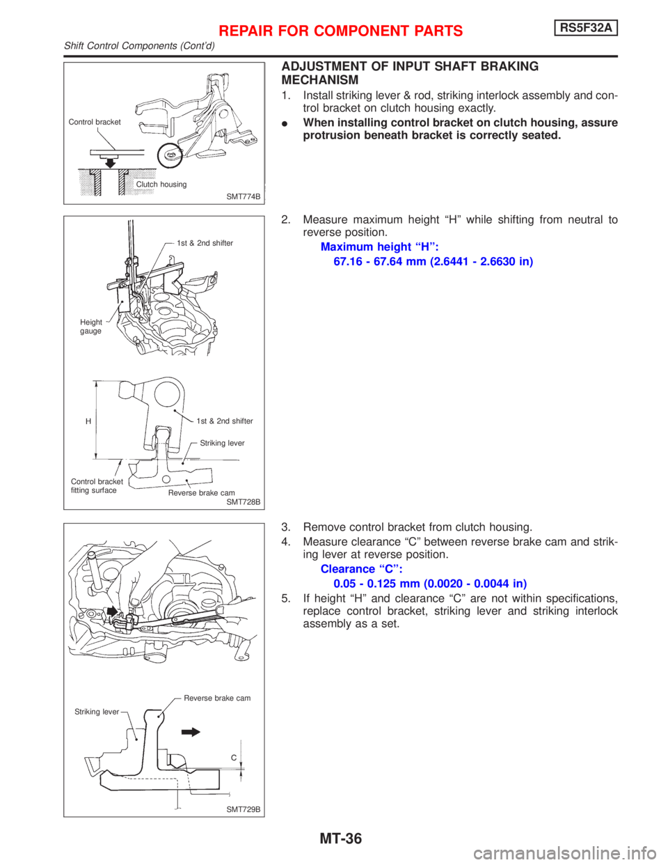
1. Install striking lever & rod, striking interlock assembly and con-
trol bracket on clutch housing exactly.
IWhen installing control bracket on clutch housing, assure
protrusion beneath bracket is correctly seated.
2. Measure maximum height ªHº while shifting from neutral to
reverse position.
Maximum height ªHº:
67.16 - 67.64 mm (2.6441 - 2.6630 in)
3. Remove control bracket from clutch housing.
4. Measure clearance ªCº between reverse brake cam and strik-
ing lever at reverse position.
Clearance ªCº:
0.05 - 0.125 mm (0.0020 - 0.0044 in)
5. If height ªHº and clearance ªCº are not within specifications,
replace control bracket, striking lever and striking interlock
assembly as a set.
SMT774B Control bracket
Clutch housing
SMT728B 1st & 2nd shifter
Height
gauge
1st & 2nd shifter
Striking lever
Control bracket
fitting surface
.Reverse brake cam
SMT729B Reverse brake cam
Striking lever
REPAIR FOR COMPONENT PARTSRS5F32A
Shift Control Components (Cont'd)
MT-36
Page 2186 of 2267
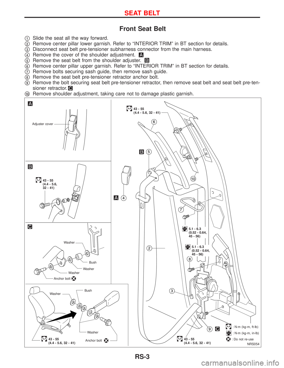
Front Seat Belt
p1Slide the seat all the way forward.
p2Remove center pillar lower garnish. Refer to ªINTERIOR TRIMº in BT section for details.
p3Disconnect seat belt pre-tensioner subharness connector from the main harness.
p4Remove the cover of the shoulder adjustment.
p5Remove the seat belt from the shoulder adjuster.
p6Remove center pillar upper garnish. Refer to ªINTERIOR TRIMº in BT section for details.
p7Remove bolts securing sash guide, then remove sash guide.
p8Remove the seat belt pre-tensioner retractor anchor bolt.
p9Remove the bolt securing seat belt pre-tensioner retractor, then remove seat belt and seat belt pre-ten-
sioner retractor.
p10Remove shoulder adjustment, taking care not to damage plastic garnish.
NRS054
Adjuster cover
WasherBush
Washer
Anchor bolt
43-55(4.4 - 5.6, 32 - 41)
43-55
(4.4 - 5.6, 32 - 41)
.5.1 - 6.3
(0.52 - 0.64,
45 - 56)
.5.1 - 6.3
(0.52 - 0.64,
45 - 56)
.43-55(4.4 - 5.6, 32 - 41)
43-55
(4.4 - 5.6,
32 - 41)
.: N´m (kg-m, ft-lb)
: N´m (kg-m, in-lb)
: Do not re-use WasherBush
Washer
Anchor bolt
Washer
SEAT BELT
RS-3