1999 NISSAN PRIMERA air filter
[x] Cancel search: air filterPage 137 of 2267
Removal
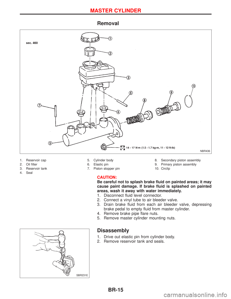
1. Reservoir cap
2. Oil filter
3. Reservoir tank
4. Seal5. Cylinder body
6. Elastic pin
7. Piston stopper pin8. Secondary piston assembly
9. Primary piston assembly
10. Circlip
CAUTION:
Be careful not to splash brake fluid on painted areas; it may
cause paint damage. If brake fluid is splashed on painted
areas, wash it away with water immediately.
1. Disconnect fluid level connector.
2. Connect a vinyl tube to air bleeder valve.
3. Drain brake fluid from each air bleeder valve, depressing
brake pedal to empty fluid from master cylinder.
4. Remove brake pipe flare nuts.
5. Remove master cylinder mounting nuts.
Disassembly
1. Drive out elastic pin from cylinder body.
2. Remove reservoir tank and seals.
NBR436
SBR231E
MASTER CYLINDER
BR-15
Page 301 of 2267
Precautions
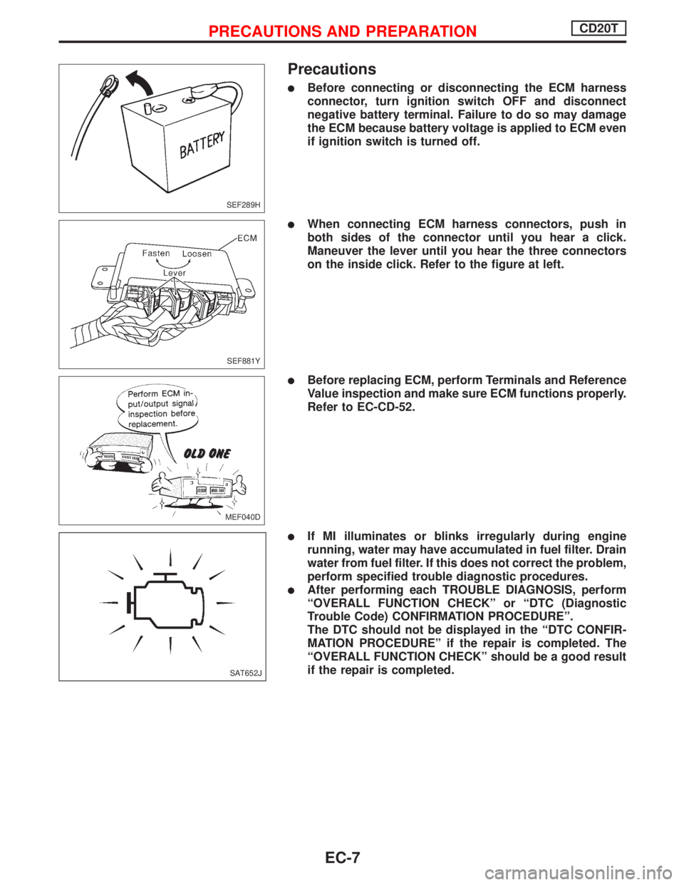
lBefore connecting or disconnecting the ECM harness
connector, turn ignition switch OFF and disconnect
negative battery terminal. Failure to do so may damage
the ECM because battery voltage is applied to ECM even
if ignition switch is turned off.
lWhen connecting ECM harness connectors, push in
both sides of the connector until you hear a click.
Maneuver the lever until you hear the three connectors
on the inside click. Refer to the figure at left.
lBefore replacing ECM, perform Terminals and Reference
Value inspection and make sure ECM functions properly.
Refer to EC-CD-52.
lIf MI illuminates or blinks irregularly during engine
running, water may have accumulated in fuel filter. Drain
water from fuel filter. If this does not correct the problem,
perform specified trouble diagnostic procedures.
lAfter performing each TROUBLE DIAGNOSIS, perform
ªOVERALL FUNCTION CHECKº or ªDTC (Diagnostic
Trouble Code) CONFIRMATION PROCEDUREº.
The DTC should not be displayed in the ªDTC CONFIR-
MATION PROCEDUREº if the repair is completed. The
ªOVERALL FUNCTION CHECKº should be a good result
if the repair is completed.
SEF289H
SEF881Y
MEF040D
SAT652J
PRECAUTIONS AND PREPARATIONCD20T
EC-7
Page 331 of 2267
Basic Inspection
Precaution:
Perform Basic Inspection without electrical or mechanical
loads applied;
lHeadlamp switch is off,
lAir Conditioner switch is off,
lRear defogger switch is off,
lSteering wheel is in the straight-ahead position, etc.
BEFORE STARTING
1. Check service records for any
recent repairs that may indicate a
related problem, or the current need
for scheduled maintenance.
2. Open engine hood and check the
following:
lHarness connectors for faulty con-
nections
lVacuum hoses for splits, kinks, or
faulty connections
lWiring for faulty connections,
pinches, or cuts
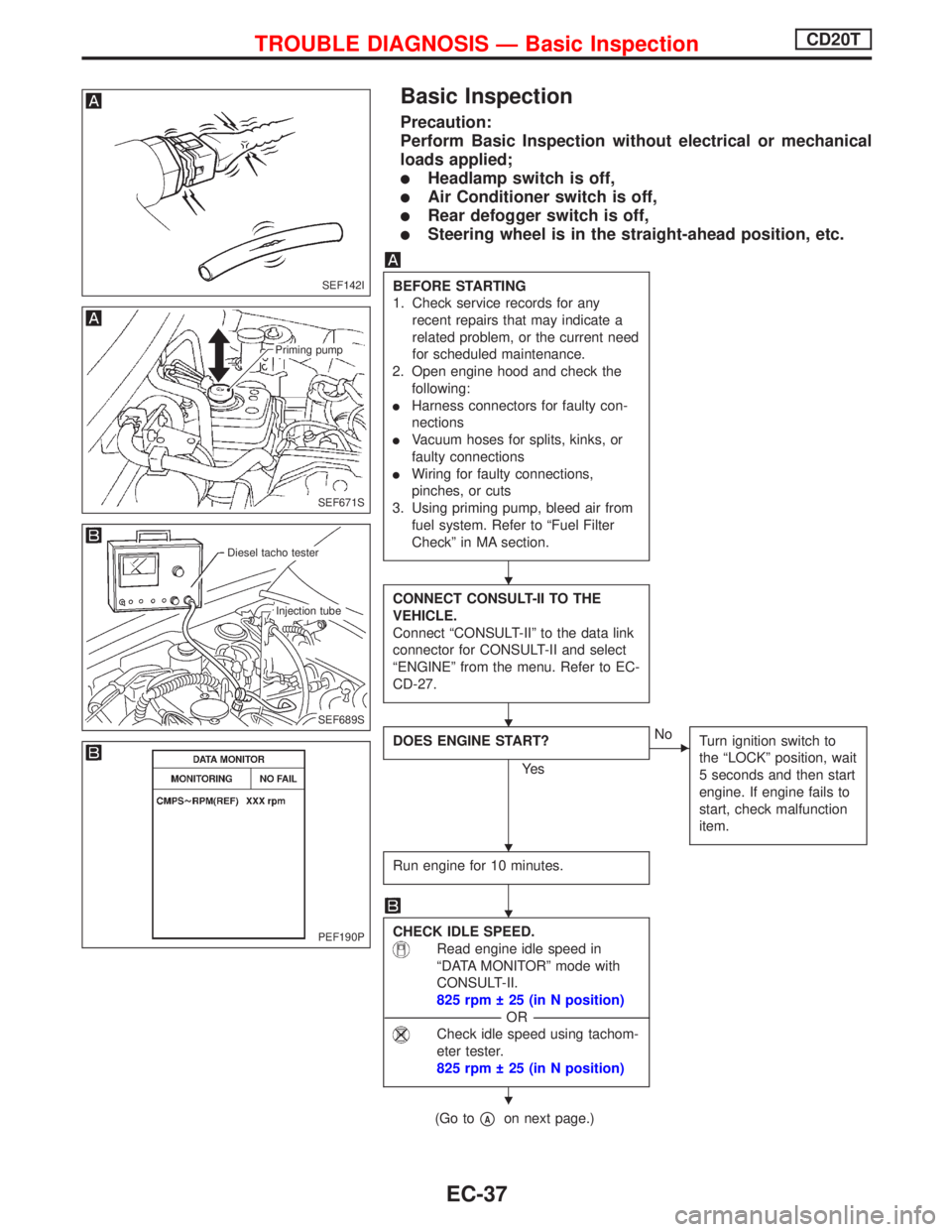
3. Using priming pump, bleed air from
fuel system. Refer to ªFuel Filter
Checkº in MA section.
CONNECT CONSULT-II TO THE
VEHICLE.
Connect ªCONSULT-IIº to the data link
connector for CONSULT-II and select
ªENGINEº from the menu. Refer to EC-
CD-27.
DOES ENGINE START?
Ye s
ENo
Turn ignition switch to
the ªLOCKº position, wait
5 seconds and then start
engine. If engine fails to
start, check malfunction
item.
Run engine for 10 minutes.
CHECK IDLE SPEED.
Read engine idle speed in
ªDATA MONITORº mode with
CONSULT-II.
825 rpm 25 (in N position)
---------------------------------------------------------------------------------------------------------------------------------OR---------------------------------------------------------------------------------------------------------------------------------
Check idle speed using tachom-
eter tester.
825 rpm 25 (in N position)
(Go topAon next page.)
SEF142I
SEF671S
Priming pump
SEF689S
.Diesel tacho tester
.Injection tube
PEF190P
H
H
H
H
H
TROUBLE DIAGNOSIS Ð Basic InspectionCD20T
EC-37
Page 332 of 2267
pA
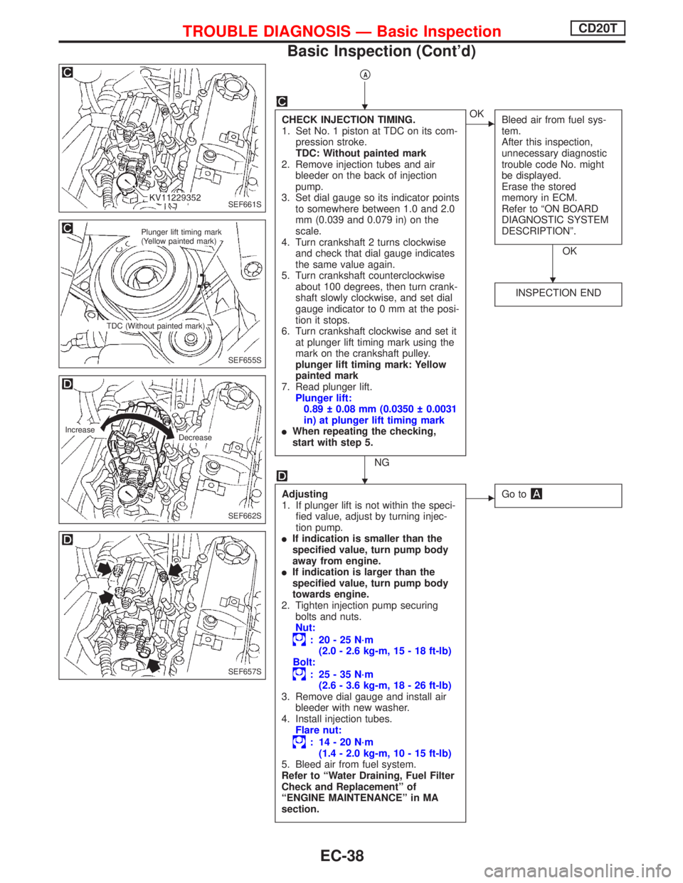
CHECK INJECTION TIMING.
1. Set No. 1 piston at TDC on its com-
pression stroke.
TDC: Without painted mark
2. Remove injection tubes and air
bleeder on the back of injection
pump.
3. Set dial gauge so its indicator points
to somewhere between 1.0 and 2.0
mm (0.039 and 0.079 in) on the
scale.
4. Turn crankshaft 2 turns clockwise
and check that dial gauge indicates
the same value again.
5. Turn crankshaft counterclockwise
about 100 degrees, then turn crank-
shaft slowly clockwise, and set dial
gauge indicator to 0 mm at the posi-
tion it stops.
6. Turn crankshaft clockwise and set it
at plunger lift timing mark using the
mark on the crankshaft pulley.
plunger lift timing mark: Yellow
painted mark
7. Read plunger lift.
Plunger lift:
0.89 0.08 mm (0.0350 0.0031
in) at plunger lift timing mark
lWhen repeating the checking,
start with step 5.
NG
EOK
Bleed air from fuel sys-
tem.
After this inspection,
unnecessary diagnostic
trouble code No. might
be displayed.
Erase the stored
memory in ECM.
Refer to ªON BOARD
DIAGNOSTIC SYSTEM
DESCRIPTIONº.
OK
INSPECTION END
Adjusting
1. If plunger lift is not within the speci-
fied value, adjust by turning injec-
tion pump.
lIf indication is smaller than the
specified value, turn pump body
away from engine.
lIf indication is larger than the
specified value, turn pump body
towards engine.
2. Tighten injection pump securing
bolts and nuts.
Nut:
: 20-25N´m
(2.0 - 2.6 kg-m, 15 - 18 ft-lb)
Bolt:
: 25-35N´m
(2.6 - 3.6 kg-m, 18 - 26 ft-lb)
3. Remove dial gauge and install air
bleeder with new washer.
4. Install injection tubes.
Flare nut:
: 14-20N´m
(1.4 - 2.0 kg-m, 10 - 15 ft-lb)
5. Bleed air from fuel system.
Refer to ªWater Draining, Fuel Filter
Check and Replacementº of
ªENGINE MAINTENANCEº in MA
section.
EGo to
SEF661S
SEF655S
Plunger lift timing mark
(Yellow painted mark)
TDC (Without painted mark)
SEF662S
Increase
Decrease
SEF657S
H
H
H
TROUBLE DIAGNOSIS Ð Basic InspectionCD20T
Basic Inspection (Cont'd)
EC-38
Page 378 of 2267
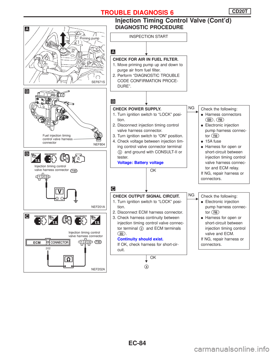
DIAGNOSTIC PROCEDURE
INSPECTION START
CHECK FOR AIR IN FUEL FILTER.
1. Move priming pump up and down to
purge air from fuel filter.
2. Perform ªDIAGNOSTIC TROUBLE
CODE CONFIRMATION PROCE-
DUREº.
CHECK POWER SUPPLY.
1. Turn ignition switch to ªLOCKº posi-
tion.
2. Disconnect injection timing control
valve harness connector.
3. Turn ignition switch to ªONº position.
4. Check voltage between injection tim-
ing control valve connector terminal
p3and ground with CONSULT-II or
tester.
Voltage: Battery voltage
OK
ENG
Check the following:
lHarness connectors
E89,F96
lElectronic injection
pump harness connec-
tor
F49
l15A fuse
lHarness for open or
short-circuit between
injection timing control
valve harness connec-
tor and ECM relay.
If NG, repair harness or
connectors.
CHECK OUTPUT SIGNAL CIRCUIT.
1. Turn ignition switch to ªLOCKº posi-
tion.
2. Disconnect ECM harness connector.
3. Check harness continuity between
injection timing control valve connec-
tor terminal
p2and ECM terminals
202.
Continuity should exist.
If OK, check harness for short-cir-
cuit.
OK
ENG
Check the following:
lElectronic injection
pump harness connec-
tor
F49
lHarness for open or
short-circuit between
injection timing control
valve and ECM.
If NG, repair harness or
connectors.
pA
SEF671S
Priming pump
NEF804
Fuel injection timing
control valve harness
connector
NEF201A
Injection timing control
valve harness connector
NEF202A
Injection timing control
valve harness connector
H
H
H
H
TROUBLE DIAGNOSIS 6CD20T
Injection Timing Control Valve (Cont'd)
EC-84
Page 393 of 2267
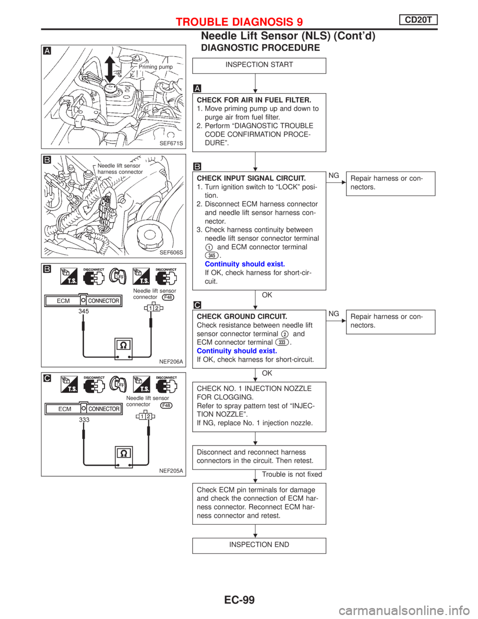
DIAGNOSTIC PROCEDURE
INSPECTION START
CHECK FOR AIR IN FUEL FILTER.
1. Move priming pump up and down to
purge air from fuel filter.
2. Perform ªDIAGNOSTIC TROUBLE
CODE CONFIRMATION PROCE-
DUREº.
CHECK INPUT SIGNAL CIRCUIT.
1. Turn ignition switch to ªLOCKº posi-
tion.
2. Disconnect ECM harness connector
and needle lift sensor harness con-
nector.
3. Check harness continuity between
needle lift sensor connector terminal
p1and ECM connector terminal
345.
Continuity should exist.
If OK, check harness for short-cir-
cuit.
OK
ENG
Repair harness or con-
nectors.
CHECK GROUND CIRCUIT.
Check resistance between needle lift
sensor connector terminal
p2and
ECM connector terminal
333.
Continuity should exist.
If OK, check harness for short-circuit.
OK
ENG
Repair harness or con-
nectors.
CHECK NO. 1 INJECTION NOZZLE
FOR CLOGGING.
Refer to spray pattern test of ªINJEC-
TION NOZZLEº.
If NG, replace No. 1 injection nozzle.
Disconnect and reconnect harness
connectors in the circuit. Then retest.
Trouble is not fixed
Check ECM pin terminals for damage
and check the connection of ECM har-
ness connector. Reconnect ECM har-
ness connector and retest.
INSPECTION END
SEF671S
Priming pump
SEF606S
Needle lift sensor
harness connector
NEF206A
Needle lift sensor
connector
NEF205A
Needle lift sensor
connector
H
H
H
H
H
H
H
TROUBLE DIAGNOSIS 9CD20T
Needle Lift Sensor (NLS) (Cont'd)
EC-99
Page 654 of 2267
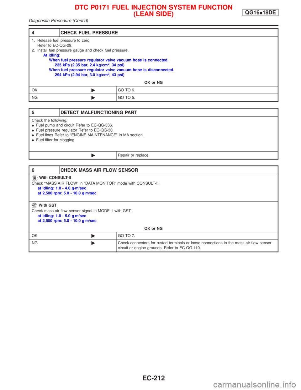
4 CHECK FUEL PRESSURE
1. Release fuel pressure to zero.
Refer to EC-QG-29.
2. Install fuel pressure gauge and check fuel pressure.
At idling:
When fuel pressure regulator valve vacuum hose is connected.
235 kPa (2.35 bar, 2.4 kg/cm
2, 34 psi)
When fuel pressure regulator valve vacuum hose is disconnected.
294 kPa (2.94 bar, 3.0 kg/cm
2, 43 psi)
OK or NG
OK©GO TO 6.
NG©GO TO 5.
5 DETECT MALFUNCTIONING PART
Check the following.
IFuel pump and circuit Refer to EC-QG-336.
IFuel pressure regulator Refer to EC-QG-30.
IFuel lines Refer to ªENGINE MAINTENANCEº in MA section.
IFuel filter for clogging
©Repair or replace.
6 CHECK MASS AIR FLOW SENSOR
With CONSULT-II
Check ªMASS AIR FLOWº in ªDATA MONITORº mode with CONSULT-II.
at idling: 1.0 - 4.0 g×m/sec
at 2,500 rpm: 5.0 - 10.0 g×m/sec
With GST
Check mass air flow sensor signal in MODE 1 with GST.
at idling: 1.0 - 5.0 g×m/sec
at 2,500 rpm: 5.0 - 10.0 g×m/sec
OK or NG
OK©GO TO 7.
NG©Check connectors for rusted terminals or loose connections in the mass air flow sensor
circuit or engine grounds. Refer to EC-QG-110.
DTC P0171 FUEL INJECTION SYSTEM FUNCTION
(LEAN SIDE)QG16I18DE
Diagnostic Procedure (Cont'd)
EC-212
Page 668 of 2267
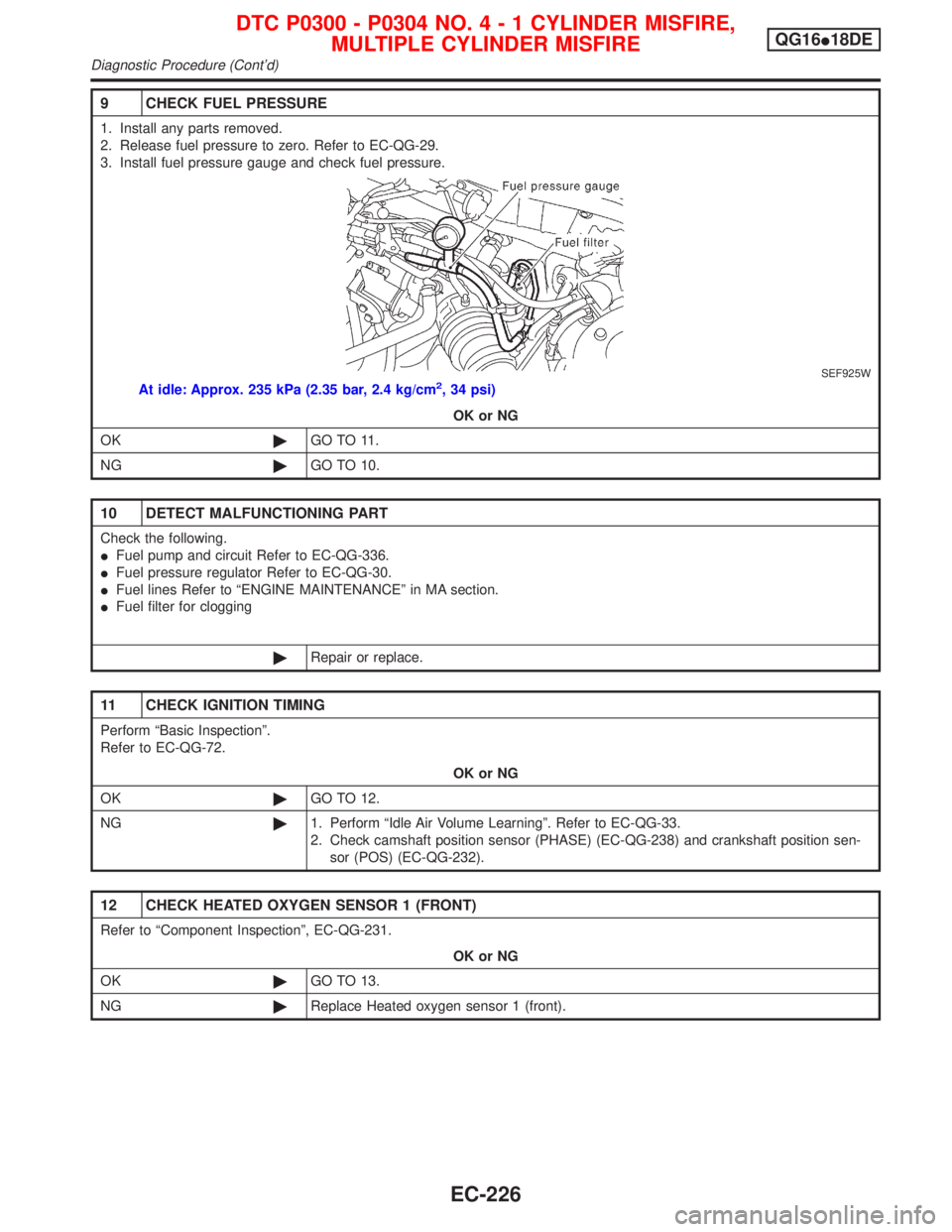
9 CHECK FUEL PRESSURE
1. Install any parts removed.
2. Release fuel pressure to zero. Refer to EC-QG-29.
3. Install fuel pressure gauge and check fuel pressure.
SEF925W
At idle: Approx. 235 kPa (2.35 bar, 2.4 kg/cm2, 34 psi)
OK or NG
OK©GO TO 11.
NG©GO TO 10.
10 DETECT MALFUNCTIONING PART
Check the following.
IFuel pump and circuit Refer to EC-QG-336.
IFuel pressure regulator Refer to EC-QG-30.
IFuel lines Refer to ªENGINE MAINTENANCEº in MA section.
IFuel filter for clogging
©Repair or replace.
11 CHECK IGNITION TIMING
Perform ªBasic Inspectionº.
Refer to EC-QG-72.
OK or NG
OK©GO TO 12.
NG©1. Perform ªIdle Air Volume Learningº. Refer to EC-QG-33.
2. Check camshaft position sensor (PHASE) (EC-QG-238) and crankshaft position sen-
sor (POS) (EC-QG-232).
12 CHECK HEATED OXYGEN SENSOR 1 (FRONT)
Refer to ªComponent Inspectionº, EC-QG-231.
OK or NG
OK©GO TO 13.
NG©Replace Heated oxygen sensor 1 (front).
DTC P0300 - P0304 NO.4-1CYLINDER MISFIRE,
MULTIPLE CYLINDER MISFIREQG16I18DE
Diagnostic Procedure (Cont'd)
EC-226