1999 NISSAN PRIMERA air filter
[x] Cancel search: air filterPage 1851 of 2267
Removal and Installation ......................................... 81
Control Linkage Adjustment..................................... 82
SYSTEM DESCRIPTION............................................. 84
Overview of Control System .................................... 84
Control System Input Components ......................... 84
Control System Auto Amplifier (Auto amp.)............. 87
Control System Output Components....................... 90
SERVICE PROCEDURES......................................... 100
HFC-134a (R-134a) Service Procedure ................ 100
Maintenance of Lubricant Quantity in
Compressor ........................................................... 102
Refrigerant Lines ................................................... 104Checking Refrigerant Leaks .................................. 106
Compressor Mounting ........................................... 109
Compressor - Model CR-14 (Calsonic make) ........ 111
Compressor Clutch ................................................. 111
Thermal Protector ................................................... 113
CSV613 Compressor .............................................. 114
Compressor Clutch ................................................. 114
Ventilation Air Filter ................................................. 117
SERVICE DATA AND SPECIFICATIONS (SDS)....... 118
General Specifications ............................................ 118
Inspection and Adjustment ..................................... 118
HA-2
Page 1966 of 2267
BREAK-IN OPERATION
When replacing compressor clutch assembly, always carry out
the break-in operation. This is done by engaging and disengag-
ing the clutch about thirty times. Break-in operation raises the
level of transmitted torque.
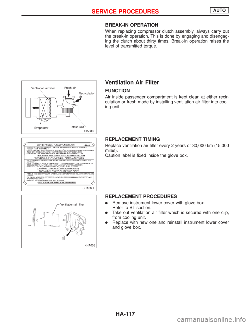
Ventilation Air Filter
FUNCTION
Air inside passenger compartment is kept clean at either recir-
culation or fresh mode by installing ventilation air filter into cool-
ing unit.
REPLACEMENT TIMING
Replace ventilation air filter every 2 years or 30,000 km (15,000
miles).
Caution label is fixed inside the glove box.
REPLACEMENT PROCEDURES
lRemove instrument lower cover with glove box.
Refer to BT section.
lTake out ventilation air filter which is secured with one clip,
from cooling unit.
lReplace with new one and reinstall instrument lower cover
and glove box.
RHA336F Ventilation air filterFresh air
Recirculation
air
EvaporatorIntake unit
SHA868E
KHA058 Ventilation air filter
SERVICE PROCEDURESAUTO
HA-117
Page 1969 of 2267
A
AAC/V - Wiring diagram....EC-QG-276, EC-SR-265
ABS (anti-lock brake system).........................BR-50
A/C control linkage adjustment (manual
A/C) .............................................................HA-82
A/C control operation (auto A/C) ....................HA-19
A/C diagnostic work flow (auto A/C) ..............HA-26
A/C performance chart ...................................HA-35
A/C performance test diagnoses....................HA-33
A/C relay.........................................................HA-78
A/C service data specification ......................HA-118
A/C switch ......................................................HA-78
A/C symptom chart (auto A/C) .......................HA-28
A/C trouble diagnoses (auto A/C) ..................HA-26
Accelerator control system ...............................FE-3
Accelerator position sensor ...................EC-CD-108
Accelerator position switch ....................EC-CD-108
Accelerator wire adjustment .............................FE-4
A/CCUT - Wiring diagram ......................EC-CD-127
Air bag disposal..............................................RS-27
Air bag precautions ...........................................GI-3
Air bleeding for brake system ..........................BR-8
Air cleaner filter replacement ............MA-23, 34, 44
Air conditioner cut
control .....EC-QG-24, EC-SR-26, EC-CD-20, 126
Air flow meter - See Mass air flow
sensor ............................EC-QG-110, EC-SR-120
Air mix. door motor.........................................HA-92
Alternator ..................................................EL-53, 56
Ambient sensor ..............................................HA-86
Antenna .........................................................EL-229
Anti-lock brake system - See ABS .................BR-50
APS - Wiring diagram ............................EC-CD-109
A/T - Wiring diagram - AT - FTS .....................AT-56
A/T - Wiring diagram - AT - MAIN ...................AT-45
A/T - Wiring diagram - AT - PNP/SW..............AT-50
A/T - Wiring diagram - AT - VSS A/T ..............AT-64
A/T diagnosis communication line .........EC-SR-295
A/T fluid temperature sensor...........................AT-54
A/T trouble diagnoses ...............................AT-29, 30
A/T Wiring diagram - AT - ENG SS ................AT-67
A/T Wiring diagram AT - LPSV .......................AT-76
A/T Wiring diagram AT - TCV .........................AT-71
A/T Wiring diagram AT - TPS..........................AT-81
ATDIAG - Wiring diagram ......................EC-SR-296
Audio .............................................................EL-216
AUDIO - Wiring diagram ...............................EL-219
Audio and A/C control removal and
installation - See Instrument panel .............BT-15
Auto air conditioner - Wiring diagram ............HA-42
Automatic amplifier .........................................HA-87
Automatic transaxle number............................GI-44
Automatic transmission fluid
replacement..........................................MA-49, 50
Auxiliary air control (AAC)
valve ..............................EC-QG-274, EC-SR-263BBack door opener - See Back door ............BT-9, 11
Back door trim.................................................BT-30
Back door window ....................................BT-35, 56
Back-up lamp ................................................EL-107
BACK/L - Wiring diagram..............................EL-107
Ball joint front axle ....................................FA-32, 33
Base idle air volume
initialiging ...........................EC-QG-33, EC-SR-46
Basic inspection ....................EC-QG-72, EC-SR-84
Battery .............................................................EL-29
Body alignment ...............................................BT-60
Brake booster .................................................BR-18
Brake control valve (Proportioning
valve)...........................................................BR-11
Brake fluid change ...........................................BR-7
Brake fluid level .............................................MA-51
Brake fluid level and line check .......................BR-7
Brake hydraulic line ..........................................BR-9
Brake inspection ............................................MA-51
Brake lining wear temporary checking ..........MA-51
Brake pedal ....................................................BR-13
Bulb specifications ........................................EL-137
Bumper, front ....................................................BT-5
Bumper, rear .......................................BT-5, 7, 9, 11
BUZZER - Wiring diagram ............................EL-181
C
Camshaft inspection ...............EM-35, 91, 138, 147,
183, 192, 196
Camshaft position sensor
(CMPS) ..........................EC-QG-238, EC-SR-239
Camshaft position sensor (PHASE) ......EC-QG-238
Canister-See EVAP
canister ..............................EC-QG-25, EC-SR-27
CHARGE - Wiring diagram .............................EL-53
Charging system .............................................EL-53
Chassis and body maintenance ....................MA-48
CHIME - Wiring diagram ...............................EL-181
Cigarette lighter.............................................EL-203
Circuit breaker.................................................EL-22
CKPS - Wiring diagram....EC-QG-234, EC-SR-236,
292, EC-CD-115
Clock .............................................................EL-203
Closed throttle position switch ...............EC-SR-271
Clutch cover ....................................................CL-13
Clutch damper ................................................CL-10
Clutch disc ......................................................CL-13
Clutch fluid level.............................................MA-48
Clutch master cylinder ......................................CL-8
Clutch operating cylinder ..................................CL-9
Clutch release mechanism..............................CL-11
CMPS - Wiring diagram ....EC-QG-240, EC-SR-242
Coil spring (rear) .............................................RA-11
Collision diagnosis..........................................RS-57
Combination meter........................................EL-138
ALPHABETICAL INDEX
IDX-2
Page 1971 of 2267
Evaporative emission (EVAP)
system ...............................EC-QG-25, EC-SR-27
Exhaust gas recirculation (EGR)
valve...........................................EC-QG-244, 305
Exhaust system ................................................FE-9
Exhaust system inspection ............................MA-48
Exterior ............................................................BT-31
F
FCUT - Wiring diagram ..........................EC-CD-101
F/FOG - Wiring diagram................................EL-110
Final drive (FF M/T) ...........................MT-32, 51, 71
Floor trim .........................................................BT-18
Fluid temperature sensor (A/T) .......................AT-94
Fluids..............................................................MA-16
Flywheel (clutch) .............................................CL-14
Flywheel runout..............................EM-60, 117, 177
Fog lamp, front ..............................................EL-110
Fog lamp, rear ...............................................EL-112
F/PUMP - Wiring
diagram..........................EC-QG-338, EC-SR-317
Freeze frame data ................EC-QG-38, EC-SR-50
Fresh vent door control linkage
adjustment ..................................................HA-83
FRO2 - Wiring diagram ........EC-QG-135, 154, 162,
EC-SR-147, 165, 172
FRO2/H - Wiring
diagram..........................EC-QG-168, EC-SR-177
Front axle ..........................................................FA-9
Front bumper ....................................................BT-5
Front disc brake .............................................BR-23
Front door .......................................................BT-13
Front fog lamp .......................................EL-110, 111
Front fog lamp removal and installation ...........BT-5
Front heated oxygen sensor
(HO2S) ......................................EC-QG-132, 139,
EC-SR-144, 150, 156, 162, 170
Front heated oxygen sensor (HO2S)
heater ............................EC-QG-166, EC-SR-175
Front passenger air bag .................................RS-17
Front seat ........................................................BT-40
Front seat belt ..................................................RS-3
Front suspension ............................................FA-26
Front washer .................................................EL-186
Front wiper ....................................................EL-186
FTS - Wiring diagram ............................EC-CD-105
FUEL - Wiring
diagram .........EC-QG-210, 217, EC-SR-213, 220
Fuel cut control (at no load & high
engine speed)....................EC-QG-25, EC-SR-27
Fuel cut solenoid valve ..........................EC-CD-100
Fuel filter ...............................EC-QG-29, EC-SR-31
Fuel filter replacement .......................MA-23, 33, 43
Fuel gauge ............................................EL-141, 146
Fuel injection system....................EC-QG-208, 215,
EC-SR-212, 218,
EC-CD-15, 18
Fuel injector ......................EC-QG-318, EC-SR-302
Fuel line inspection............................MA-22, 33, 43Fuel precautions ................................................GI-7
Fuel pressure check .............EC-QG-29, EC-SR-31
Fuel pressure regulator .........EC-QG-30, EC-SR-32
Fuel pressure release ...........EC-QG-29, EC-SR-31
Fuel pump .........................EC-QG-336, EC-SR-316
Fuel pump and gauge ......................................FE-7
Fuel pump relay ................EC-QG-336, EC-SR-316
Fuel system ......................................................FE-6
Fuel tank vacuum relief
valve ..................................EC-QG-26, EC-SR-28
Fuel temperature sensor .................EC-CD-17, 104
Fuse ..................................................EL-22, Foldout
Fuse block ....................................................Foldout
Fusible link ........................................EL-22, Foldout
G
Garage jack and safety stand .........................GI-47
Gauges..........................................................EL-138
Gear components (M/T) ...........................MT-16, 49
Generic scan tool (GST) .......EC-QG-66, EC-SR-78
GLOW - Wiring diagram ........................EC-CD-120
Glow plug .........................................EC-CD-15, 118
Glow relay ................................................EC-CD-15
GOVNR - Wiring diagram ........................EC-CD-79
Grille - See Exterior ........................................BT-38
Ground distribution..........................................EL-23
H
H/AIM - Wiring diagram ....................EL-87, 93, 200
Harness connector ............................................EL-6
Harness layout ..............................................EL-368
Hazard warning lamp ....................................EL-117
Headlamp..................................................EL-67, 69
Headlamp aiming control ................................EL-87
Headlamp washer .........................................EL-200
Headlining - See Roof trim .............................BT-25
Heated oxygen sensor (HO2S)
(front) ........................................EC-QG-132, 139,
EC-SR-144, 150, 156, 162, 170
Heated oxygen sensor (HO2S) heater
(front) .............................EC-QG-166, EC-SR-175
Heated oxygen sensor (HO2S) heater
(rear) ..............................EC-QG-203, EC-SR-207
Heated oxygen sensor (rear) ...............EC-QG-171,
EC-SR-180, 187,
194, 201
Heated oxygen sensor inspection ...........MA-27, 38
Heated seat .......................................BT-42, EL-234
HEATER - Wiring diagram .............................HA-40
HFC134a (R134a) system service
procedure ..................................................HA-100
HFC134a (R134a) system service tools ..........HA-8
H/LAMP - Wiring diagram ...............................EL-67
Hood..................................................................BT-5
Horn ..............................................................EL-203
HORN - Wiring diagram ................................EL-203
ALPHABETICAL INDEX
IDX-4
Page 2018 of 2267
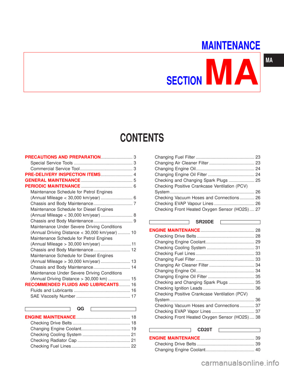
MAINTENANCE
SECTION
MA
CONTENTS
PRECAUTIONS AND PREPARATION.......................... 3
Special Service Tools ................................................ 3
Commercial Service Tool ........................................... 3
PRE-DELIVERY INSPECTION ITEMS.......................... 4
GENERAL MAINTENANCE.......................................... 5
PERIODIC MAINTENANCE.......................................... 6
Maintenance Schedule for Petrol Engines
(Annual Mileage < 30,000 km/year) .......................... 6
Chassis and Body Maintenance ................................ 7
Maintenance Schedule for Diesel Engines
(Annual Mileage < 30,000 km/year) .......................... 8
Chassis and Body Maintenance ................................ 9
Maintenance Under Severe Driving Conditions
(Annual Driving Distance < 30,000 km/year) .......... 10
Maintenance Schedule for Petrol Engines
(Annual Mileage > 30,000 km/year) ......................... 11
Chassis and Body Maintenance .............................. 12
Maintenance Schedule for Diesel Engines
(Annual Mileage > 30,000 km/year) ........................ 13
Chassis and Body Maintenance .............................. 14
Maintenance Under Severe Driving Conditions
(Annual Driving Distance > 30,000 km) .................. 15
RECOMMENDED FLUIDS AND LUBRICANTS......... 16
Fluids and Lubricants .............................................. 16
SAE Viscosity Number ............................................ 17
QG
ENGINE MAINTENANCE............................................ 18
Checking Drive Belts ............................................... 18
Changing Engine Coolant........................................ 19
Checking Cooling System ....................................... 21
Checking Radiator Cap ........................................... 21
Checking Fuel Lines ................................................ 22Changing Fuel Filter ................................................ 23
Changing Air Cleaner Filter ..................................... 23
Changing Engine Oil................................................ 24
Changing Engine Oil Filter ...................................... 24
Checking and Changing Spark Plugs ..................... 25
Checking Positive Crankcase Ventilation (PCV)
System ..................................................................... 26
Checking Vacuum Hoses and Connections ............ 26
Checking EVAP Vapour Lines ................................. 26
Checking Front Heated Oxygen Sensor (HO2S) .... 27
SR20DE
ENGINE MAINTENANCE............................................ 28
Checking Drive Belts ............................................... 28
Changing Engine Coolant........................................ 29
Checking Cooling System ....................................... 31
Checking Fuel Lines ................................................ 33
Changing Fuel Filter ................................................ 33
Changing Air Cleaner Filter ..................................... 34
Changing Engine Oil................................................ 34
Changing Engine Oil Filter ...................................... 35
Checking and Changing Spark Plugs ..................... 35
Checking Ignition Leads .......................................... 36
Checking Positive Crankcase Ventilation (PCV)
System ..................................................................... 36
Checking Vacuum Hoses and Connections ............ 37
Checking EVAP Vapor Lines ................................... 37
Checking Front Heated Oxygen Sensor (HO2S) .... 38
CD20T
ENGINE MAINTENANCE............................................ 39
Checking Drive Belts ............................................... 39
Changing Engine Coolant........................................ 40
MA
Page 2019 of 2267
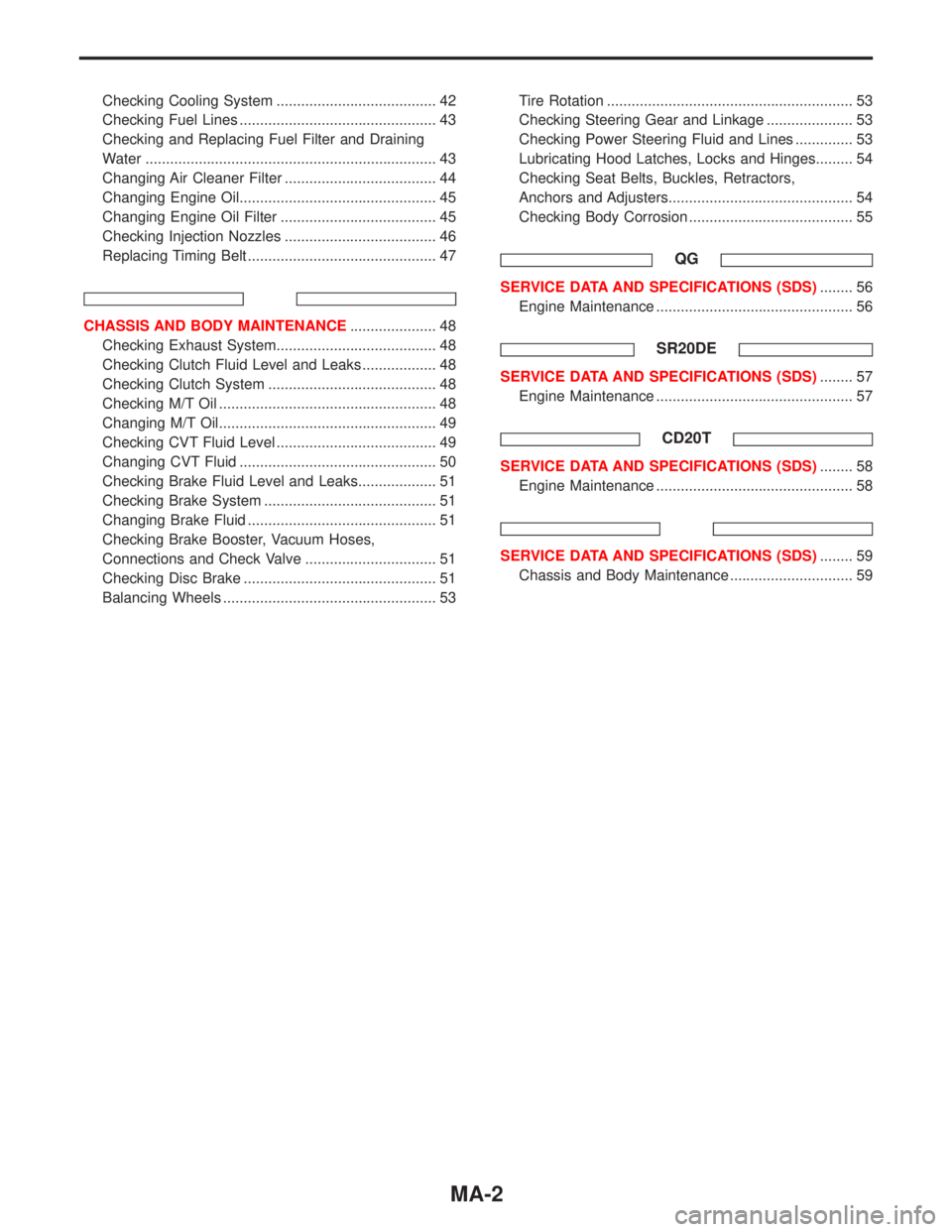
Checking Cooling System ....................................... 42
Checking Fuel Lines ................................................ 43
Checking and Replacing Fuel Filter and Draining
Water ....................................................................... 43
Changing Air Cleaner Filter ..................................... 44
Changing Engine Oil................................................ 45
Changing Engine Oil Filter ...................................... 45
Checking Injection Nozzles ..................................... 46
Replacing Timing Belt .............................................. 47
CHASSIS AND BODY MAINTENANCE..................... 48
Checking Exhaust System....................................... 48
Checking Clutch Fluid Level and Leaks .................. 48
Checking Clutch System ......................................... 48
Checking M/T Oil ..................................................... 48
Changing M/T Oil..................................................... 49
Checking CVT Fluid Level ....................................... 49
Changing CVT Fluid ................................................ 50
Checking Brake Fluid Level and Leaks................... 51
Checking Brake System .......................................... 51
Changing Brake Fluid .............................................. 51
Checking Brake Booster, Vacuum Hoses,
Connections and Check Valve ................................ 51
Checking Disc Brake ............................................... 51
Balancing Wheels .................................................... 53Tire Rotation ............................................................ 53
Checking Steering Gear and Linkage ..................... 53
Checking Power Steering Fluid and Lines .............. 53
Lubricating Hood Latches, Locks and Hinges......... 54
Checking Seat Belts, Buckles, Retractors,
Anchors and Adjusters............................................. 54
Checking Body Corrosion ........................................ 55
QG
SERVICE DATA AND SPECIFICATIONS (SDS)........ 56
Engine Maintenance ................................................ 56
SR20DE
SERVICE DATA AND SPECIFICATIONS (SDS)........ 57
Engine Maintenance ................................................ 57
CD20T
SERVICE DATA AND SPECIFICATIONS (SDS)........ 58
Engine Maintenance ................................................ 58
SERVICE DATA AND SPECIFICATIONS (SDS)........ 59
Chassis and Body Maintenance .............................. 59
MA-2
Page 2021 of 2267
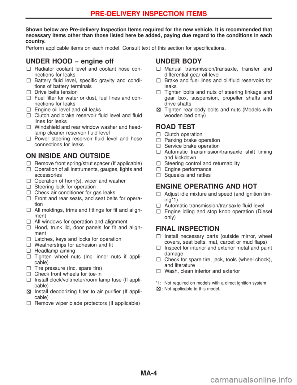
Shown below are Pre-delivery Inspection Items required for the new vehicle. It is recommended that
necessary items other than those listed here be added, paying due regard to the conditions in each
country.
Perform applicable items on each model. Consult text of this section for specifications.
UNDER HOOD � engine off
Radiator coolant level and coolant hose con-
nections for leaks
Battery fluid level, specific gravity and condi-
tions of battery terminals
Drive belts tension
Fuel filter for water or dust, fuel lines and con-
nections for leaks
Engine oil level and oil leaks
Clutch and brake reservoir fluid level and fluid
lines for leaks
Windshield and rear window washer and head-
lamp cleaner reservoir fluid level
Power steering reservoir fluid level and hose
connections for leaks
ON INSIDE AND OUTSIDE
Remove front spring/strut spacer (If applicable)
Operation of all instruments, gauges, lights and
accessories
Operation of horn(s), wiper and washer
Steering lock for operation
Check air conditioner for gas leaks
Front and rear seats, and seat belts for opera-
tion
All moldings, trims and fittings for fit and align-
ment
All windows for operation and alignment
Hood, trunk lid, door panels for fit and align-
ment
Latches, keys and locks for operation
Weatherstrips for adhesion and fit
Headlamp aiming
Tighten wheel nuts (Inc. inner nuts if appli-
cable)
Tire pressure (Inc. spare tire)
Check front wheels for toe-in
Install clock/voltmeter/room lamp fuse (If appli-
cable)
Install deodorizing filter to air purifier (If appli-
cable)
Remove wiper blade protectors (If applicable)
UNDER BODY
Manual transmission/transaxle, transfer and
differential gear oil level
Brake and fuel lines and oil/fluid reservoirs for
leaks
Tighten bolts and nuts of steering linkage and
gear box, suspension, propeller shafts and
drive shafts
Tighten rear body bolts and nuts (Models with
wooden bed only)
ROAD TEST
Clutch operation
Parking brake operation
Service brake operation
Automatic transmission/transaxle shift timing
and kickdown
Steering control and returnability
Engine performance
Squeaks and rattles
ENGINE OPERATING AND HOT
Adjust idle mixture and speed (and ignition tim-
ing*1)
Automatic transmission/transaxle fluid level
Engine idling and stop knob operation (Diesel
only)
FINAL INSPECTION
Install necessary parts (outside mirror, wheel
covers, seat belts, mat, carpet or mud flaps)
Inspect for interior and exterior metal and paint
damage
Check for spare tire, jack, tools (wheel chock),
and literature
Wash, clean interior and exterior
*1: Not required on models with a direct ignition system
: Not applicable to this model.
PRE-DELIVERY INSPECTION ITEMS
MA-4
Page 2023 of 2267
![NISSAN PRIMERA 1999 Electronic Repair Manual Maintenance Schedule for Petrol Engines
(Annual Mileage < 30,000 km/year)
QG16DE/QG18DE/SR20DE engines
Abbreviations: R = Replace I = Inspect: Correct or replace if necessary [ ] = At the specified mi NISSAN PRIMERA 1999 Electronic Repair Manual Maintenance Schedule for Petrol Engines
(Annual Mileage < 30,000 km/year)
QG16DE/QG18DE/SR20DE engines
Abbreviations: R = Replace I = Inspect: Correct or replace if necessary [ ] = At the specified mi](/manual-img/5/57377/w960_57377-2022.png)
Maintenance Schedule for Petrol Engines
(Annual Mileage < 30,000 km/year)
QG16DE/QG18DE/SR20DE engines
Abbreviations: R = Replace I = Inspect: Correct or replace if necessary [ ] = At the specified mileage only
MAINTENANCE OPERATION MAINTENANCE INTERVAL
Perform on a kilometer basis, but on
an annual basis when driving less
than 15,000 km (9,000 miles) per yearkm×1,000 15 30 45 60 75 90 105 120
(miles×1,000) (9) (18) (27) (36) (45) (54) (63) (72)
Months 12 24 36 48 60 72 84 96QG16DE/
QG18DESR20DE
Engine compartment and under vehicleReference pages
Engine oil (Use recommended oil)*RRRRRRRRMA-24 MA-34
Engine oil filter (Use NISSAN genuine
part or equivalent)*RRRRRRRRMA-24 MA-35
Drive beltsIIIIIIIIMA-18 MA-28
Cooling systemIIIIIIIIMA-21 MA-31
Engine anti-freeze coolant (Use genuine
NISSAN Anti-Freeze Coolant (L2N) or
equivalent)See NOTE (1) MA-19 MA-29
Air cleaner filter* R R MA-23 MA-34
Intake and exhaust valve clearance
(Non HLA models)See NOTE (2) EM-92—
Fuel and vapour linesIIIIMA-22/MA-26MA-33/
MA-37
Spark plugs (Conventional type)RRRRMA-25 MA-35
Ignition leads I I—MA-36
Fuel filter*R MA-23 MA-33
Heated oxygen sensor* See NOTE (3)MA-27,
EC-QG-134/
EC-QG-173MA-38,
EC-SR-146/
EC-SR-182
PCVsystem IIIIMA-26MA-36
NOTE: (1) First replace at 90,000 km (54,000 miles)/72 months, then every 60,000 km (36,000 miles)/48 months.
(2) Periodic maintenance is not required for QG engine models. However, if valve noise increases, check valve clear-
ance.
(3) Perform only according to“Maintenance under severe driving conditions”.
* Maintenance items with“*”should be performed more frequently according to“Maintenance under severe driv-
ing conditions”.
PERIODIC MAINTENANCE
MA-6