1999 NISSAN PRIMERA OBD port
[x] Cancel search: OBD portPage 9 of 2267
The blinking of the CVT or SPORT indicator lamp for about 8 seconds will appear only once and be cleared.
The customer may resume normal driving conditions.
Always follow the ªWORK FLOWº (Refer to AT-32).
The SELF-DIAGNOSIS results will be as follows:
The first SELF-DIAGNOSIS will indicate damage to the vehicle speed sensor or the revolution sensor.
During the next SELF-DIAGNOSIS, performed after checking the sensor, no damages will be indicated.
OBD SELF-DIAGNOSISNCAT0004S04ICVT self-diagnosis is performed by the TCM in combination with the ECM. The results can be read through
the blinking pattern of the CVT or SPORT indicator. Refer to the table on AT-19 for the indicator used to
display each self-diagnostic result.
IThe self-diagnostic results indicated by the MI are automatically stored in both the ECM and TCM memo-
ries.
Always perform the procedure ªHOW TO ERASE DTCº on AT-16 to complete the repair and avoid
unnecessary blinking of the MI.
For details of OBD, refer to EC section (ªON BOARD DIAGNOSTIC SYSTEM DESCRIPTIONº).
ICertain systems and components, especially those related to OBD, may use a new style slide-
locking type harness connector.
For description and how to disconnect, refer to EL section, ªDescriptionº, ªHARNESS CONNEC-
TORº.
Wiring Diagrams and Trouble DiagnosisNCAT0005When you read wiring diagrams, refer to the followings:
IªHOW TO READ WIRING DIAGRAMSº in GI section
IªPOWER SUPPLY ROUTINGº for power distribution circuit in EL section
When you perform trouble diagnosis, refer to the followings:
IªHOW TO FOLLOW TEST GROUP IN TROUBLE DIAGNOSISº in GI section
IªHOW TO PERFORM EFFICIENT DIAGNOSIS FOR AN ELECTRICAL INCIDENTº in GI section
PRECAUTIONS
Service Notice or Precautions (Cont'd)
AT-7
Page 17 of 2267
IntroductionNCAT0017The CVT system has two self-diagnostic systems.
The first is the emission-related on board diagnostic system (OBD) performed by the TCM in combination with
the ECM. The malfunction is indicated by the MI (malfunction indicator) and is stored as a DTC in the ECM
memory but not the TCM memory.
The second is the TCM original self-diagnosis indicated by the CVT indicator (warning) lamp or SPORT indi-
cator lamp. The malfunction is stored in the TCM memory. The detected items are overlapped with OBD self-
diagnostic items. For detail, refer to AT-26.
OBD Function for CVT SystemNCAT0018The ECM provides emission-related on board diagnostic (OBD) functions for the CVT system. One function
is to receive a signal from the TCM used with OBD-related parts of the CVT system. The signal is sent to the
ECM when a malfunction occurs in the corresponding OBD-related part. The other function is to indicate a
diagnostic result by means of the MI (malfunction indicator) on the instrument panel. Sensors, switches and
solenoid valves are used as sensing elements.
The MI automatically illuminates in Two Trip Detection Logic when a malfunction is sensed in relation to CVT
system parts.
OBD Diagnostic Trouble Code (DTC)NCAT0020HOW TO READ DTC AND 1ST TRIP DTCNCAT0020S01DTC and 1st trip DTC can be read by the following methods.
1.(
No Tools)The number of blinks of the malfunction indicator in the Diagnostic Test Mode II (Self-Di-
agnostic Results) Examples: 0705, 0710, 0715, 0720, etc. For details, refer to EC section [ªMalfunction
Indicator (MI)º, ªON BOARD DIAGNOSTIC SYSTEM DESCRIPTIONº].
These DTCs are controlled by NISSAN.
2.(
with CONSULT-II orGST)CONSULT-II or GST (Generic Scan Tool) Examples: P0705, P0710,
P0720, P0725, etc.
These DTCs are prescribed by ISO15031-6.
(CONSULT-II also displays the malfunctioning component or system.)
I1st trip DTC No. is the same as DTC No.
IOutput of the diagnostic trouble code indicates that the indicated circuit has a malfunction.
However, in case of the Mode II and GST they do not indicate whether the malfunction is still
occurring or occurred in the past and returned to normal.
CONSULT-II can identify them as shown below. Therefore, using CONSULT-II (if available) is rec-
ommended.
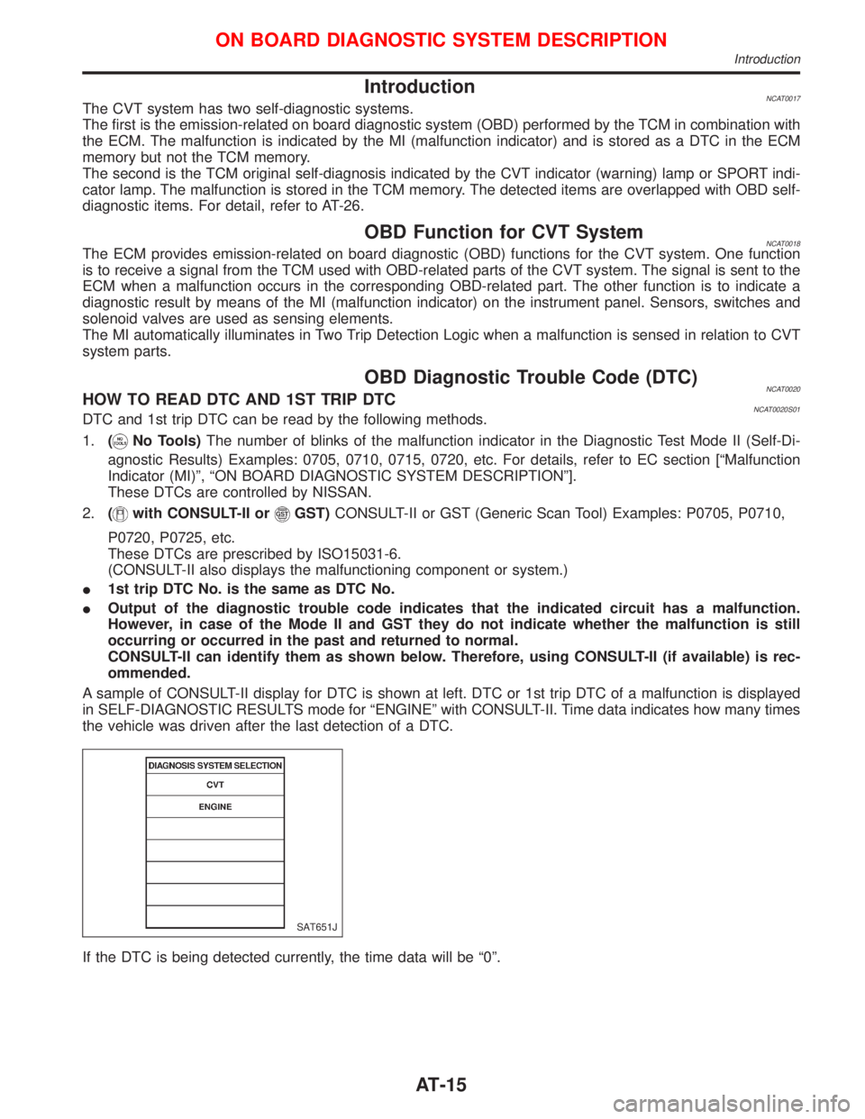
A sample of CONSULT-II display for DTC is shown at left. DTC or 1st trip DTC of a malfunction is displayed
in SELF-DIAGNOSTIC RESULTS mode for ªENGINEº with CONSULT-II. Time data indicates how many times
the vehicle was driven after the last detection of a DTC.
If the DTC is being detected currently, the time data will be ª0º.
SAT651J
ON BOARD DIAGNOSTIC SYSTEM DESCRIPTION
Introduction
AT-15
Page 21 of 2267
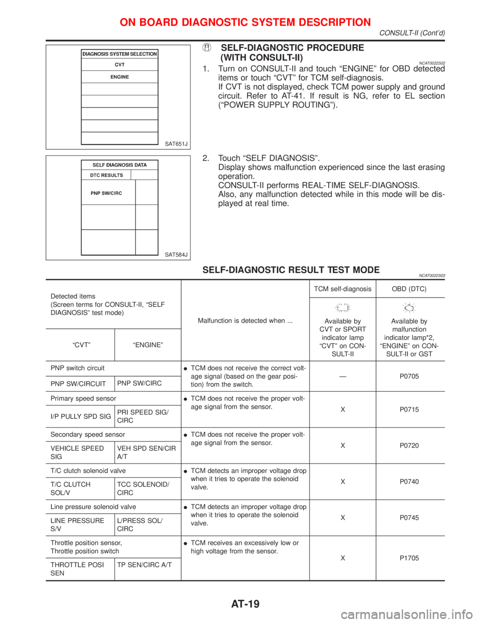
SELF-DIAGNOSTIC PROCEDURE
(WITH CONSULT-II)
NCAT0022S021. Turn on CONSULT-II and touch ªENGINEº for OBD detected
items or touch ªCVTº for TCM self-diagnosis.
If CVT is not displayed, check TCM power supply and ground
circuit. Refer to AT-41. If result is NG, refer to EL section
(ªPOWER SUPPLY ROUTINGº).
2. Touch ªSELF DIAGNOSISº.
Display shows malfunction experienced since the last erasing
operation.
CONSULT-II performs REAL-TIME SELF-DIAGNOSIS.
Also, any malfunction detected while in this mode will be dis-
played at real time.
SELF-DIAGNOSTIC RESULT TEST MODENCAT0022S03
Detected items
(Screen terms for CONSULT-II, ªSELF
DIAGNOSISº test mode)
Malfunction is detected when ...TCM self-diagnosis OBD (DTC)
Available by
CVT or SPORT
indicator lamp
ªCVTº on CON-
SULT-IIAvailable by
malfunction
indicator lamp*2,
ªENGINEº on CON-
SULT-II or GST ªCVTº ªENGINEº
PNP switch circuitITCM does not receive the correct volt-
age signal (based on the gear posi-
tion) from the switch.Ð P0705
PNP SW/CIRCUITPNP SW/CIRC
Primary speed sensorITCM does not receive the proper volt-
age signal from the sensor.
X P0715
I/P PULLY SPD SIGPRI SPEED SIG/
CIRC
Secondary speed sensorITCM does not receive the proper volt-
age signal from the sensor.
X P0720
VEHICLE SPEED
SIGVEH SPD SEN/CIR
A/T
T/C clutch solenoid valveITCM detects an improper voltage drop
when it tries to operate the solenoid
valve.X P0740
T/C CLUTCH
SOL/VTCC SOLENOID/
CIRC
Line pressure solenoid valveITCM detects an improper voltage drop
when it tries to operate the solenoid
valve.X P0745
LINE PRESSURE
S/VL/PRESS SOL/
CIRC
Throttle position sensor,
Throttle position switchITCM receives an excessively low or
high voltage from the sensor.
X P1705
THROTTLE POSI
SENTP SEN/CIRC A/T
SAT651J
SAT584J
ON BOARD DIAGNOSTIC SYSTEM DESCRIPTION
CONSULT-II (Cont'd)
AT-19
Page 22 of 2267
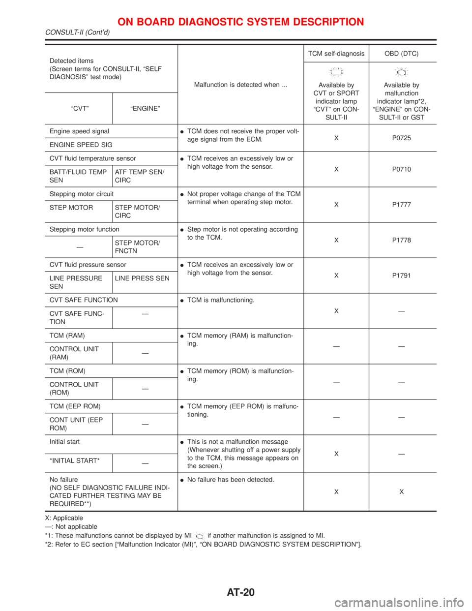
Detected items
(Screen terms for CONSULT-II, ªSELF
DIAGNOSISº test mode)
Malfunction is detected when ...TCM self-diagnosis OBD (DTC)
Available by
CVT or SPORT
indicator lamp
ªCVTº on CON-
SULT-IIAvailable by
malfunction
indicator lamp*2,
ªENGINEº on CON-
SULT-II or GST ªCVTº ªENGINEº
Engine speed signalITCM does not receive the proper volt-
age signal from the ECM.X P0725
ENGINE SPEED SIG
CVT fluid temperature sensorITCM receives an excessively low or
high voltage from the sensor.
X P0710
BATT/FLUID TEMP
SENATF TEMP SEN/
CIRC
Stepping motor circuitINot proper voltage change of the TCM
terminal when operating step motor.
X P1777
STEP MOTOR STEP MOTOR/
CIRC
Stepping motor functionIStep motor is not operating according
to the TCM.
X P1778
ÐSTEP MOTOR/
FNCTN
CVT fluid pressure sensorITCM receives an excessively low or
high voltage from the sensor.
X P1791
LINE PRESSURE
SENLINE PRESS SEN
CVT SAFE FUNCTIONITCM is malfunctioning.
XÐ
CVT SAFE FUNC-
TIONÐ
TCM (RAM)ITCM memory (RAM) is malfunction-
ing.
ÐÐ
CONTROL UNIT
(RAM)Ð
TCM (ROM)ITCM memory (ROM) is malfunction-
ing.
ÐÐ
CONTROL UNIT
(ROM)Ð
TCM (EEP ROM)ITCM memory (EEP ROM) is malfunc-
tioning.
ÐÐ
CONT UNIT (EEP
ROM)Ð
Initial startIThis is not a malfunction message
(Whenever shutting off a power supply
to the TCM, this message appears on
the screen.)XÐ
*INITIAL START*
Ð
No failure
(NO SELF DIAGNOSTIC FAILURE INDI-
CATED FURTHER TESTING MAY BE
REQUIRED**)INo failure has been detected.
XX
X: Applicable
Ð: Not applicable
*1: These malfunctions cannot be displayed by MI
if another malfunction is assigned to MI.
*2: Refer to EC section [ªMalfunction Indicator (MI)º, ªON BOARD DIAGNOSTIC SYSTEM DESCRIPTIONº].
ON BOARD DIAGNOSTIC SYSTEM DESCRIPTION
CONSULT-II (Cont'd)
AT-20
Page 118 of 2267
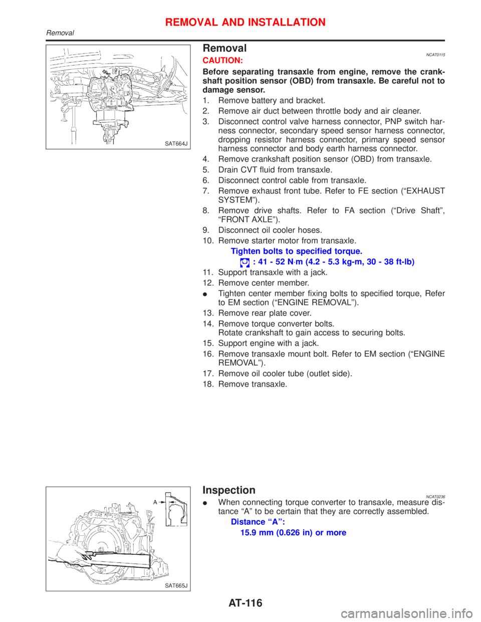
RemovalNCAT0115CAUTION:
Before separating transaxle from engine, remove the crank-
shaft position sensor (OBD) from transaxle. Be careful not to
damage sensor.
1. Remove battery and bracket.
2. Remove air duct between throttle body and air cleaner.
3. Disconnect control valve harness connector, PNP switch har-
ness connector, secondary speed sensor harness connector,
dropping resistor harness connector, primary speed sensor
harness connector and body earth harness connector.
4. Remove crankshaft position sensor (OBD) from transaxle.
5. Drain CVT fluid from transaxle.
6. Disconnect control cable from transaxle.
7. Remove exhaust front tube. Refer to FE section (ªEXHAUST
SYSTEMº).
8. Remove drive shafts. Refer to FA section (ªDrive Shaftº,
ªFRONT AXLEº).
9. Disconnect oil cooler hoses.
10. Remove starter motor from transaxle.
Tighten bolts to specified torque.
:41-52N×m (4.2 - 5.3 kg-m, 30 - 38 ft-lb)
11. Support transaxle with a jack.
12. Remove center member.
ITighten center member fixing bolts to specified torque, Refer
to EM section (ªENGINE REMOVALº).
13. Remove rear plate cover.
14. Remove torque converter bolts.
Rotate crankshaft to gain access to securing bolts.
15. Support engine with a jack.
16. Remove transaxle mount bolt. Refer to EM section (ªENGINE
REMOVALº).
17. Remove oil cooler tube (outlet side).
18. Remove transaxle.
InspectionNCAT0236IWhen connecting torque converter to transaxle, measure dis-
tance ªAº to be certain that they are correctly assembled.
Distance ªAº:
15.9 mm (0.626 in) or more
SAT664J
SAT665J
REMOVAL AND INSTALLATION
Removal
AT-116
Page 443 of 2267
ENGINE CONTROL SYSTEM
SECTION
EC
CONTENTS
QG16I18DE
TROUBLE DIAGNOSIS - INDEX....................................6
Alphabetical & P No. Index for DTC ...........................6
PRECAUTIONS...............................................................9
Supplemental Restraint System (SRS)²AIR
BAG²and²SEAT BELT PRE-TENSIONER²...............9
Precautions for On Board Diagnostic (OBD)
System of Engine ........................................................9
Engine Fuel & Emission Control System ..................10
Precautions ................................................................ 11
Wiring Diagrams and Trouble Diagnosis ...................12
PREPARATION..............................................................13
Special Service Tools ................................................13
Commercial Service Tool ...........................................13
ENGINE AND EMISSION CONTROL OVERALL
SYSTEM.........................................................................14
Engine Control Component Parts Location ...............14
Circuit Diagram ..........................................................17
System Diagram ........................................................18
Vacuum Hose Drawing ..............................................19
System Chart .............................................................20
ENGINE AND EMISSION BASIC CONTROL
SYSTEM DESCRIPTION...............................................21
Multiport Fuel Injection (MFI) System .......................21
Electronic Ignition (EI) System ..................................23
Air Conditioning Cut Control ......................................24
Fuel Cut Control (at no load & high engine
speed) ........................................................................25
Evaporative Emission System ...................................25
Positive Crankcase Ventilation ..................................28
BASIC SERVICE PROCEDURE...................................29
Fuel Pressure Release ..............................................29
Fuel Pressure Check .................................................29
Fuel Pressure Regulator Check ................................30
Injector .......................................................................30
Idle Speed/Ignition Timing/Idle Mixture Ratio
Adjustment .................................................................32Idle Air Volume Learning ...........................................33
ON BOARD DIAGNOSTIC SYSTEM
DESCRIPTION...............................................................36
Introduction ................................................................36
Two Trip Detection Logic ...........................................36
Emission-related Diagnostic Information ...................37
Malfunction Indicator (MI) ..........................................45
OBD System Operation Chart ...................................50
CONSULT-II ...............................................................55
Generic Scan Tool (GST) ..........................................66
TROUBLE DIAGNOSIS - INTRODUCTION..................68
Introduction ................................................................68
Work Flow ..................................................................70
TROUBLE DIAGNOSIS - BASIC INSPECTION...........72
Basic Inspection.........................................................72
TROUBLE DIAGNOSIS - GENERAL
DESCRIPTION...............................................................80
DTC Inspection Priority Chart....................................80
Fail-safe Chart ...........................................................81
Symptom Matrix Chart ...............................................82
CONSULT-II Reference Value in Data Monitor
Mode ..........................................................................86
Major Sensor Reference Graph in Data Monitor
Mode ..........................................................................88
ECM Terminals and Reference Value .......................91
TROUBLE DIAGNOSIS - SPECIFICATION VALUE....98
Description .................................................................98
Testing Condition .......................................................98
Inspection Procedure .................................................98
Diagnostic Procedure ................................................99
TROUBLE DIAGNOSIS FOR INTERMITTENT
INCIDENT.....................................................................102
Description ...............................................................102
Diagnostic Procedure ..............................................102
TROUBLE DIAGNOSIS FOR POWER SUPPLY........103
Main Power Supply and Ground Circuit ..................103
EC
Page 801 of 2267
ENGINE CONTROL SYSTEM
SECTION
EC
CONTENTS
SR20DE
TROUBLE DIAGNOSIS - INDEX....................................6
Alphabetical & P No. Index for DTC ...........................6
PRECAUTIONS.............................................................10
Supplemental Restraint System (SRS)²AIR
BAG²and²SEAT BELT PRE-TENSIONER².............10
Precautions for On Board Diagnostic (OBD)
System of Engine and CVT .......................................10
Engine Fuel & Emission Control System .................. 11
Precautions ................................................................12
Wiring Diagrams and Trouble Diagnosis ...................13
PREPARATION.............................................................14
Special Service Tools ................................................14
Commercial Service Tool ...........................................14
ENGINE AND EMISSION CONTROL OVERALL
SYSTEM.........................................................................15
Engine Control Component Parts Location ...............15
Circuit Diagram ..........................................................19
System Diagram ........................................................20
Vacuum Hose Drawing ..............................................21
System Chart .............................................................22
ENGINE AND EMISSION BASIC CONTROL
SYSTEM DESCRIPTION...............................................23
Multiport Fuel Injection (MFI) System .......................23
Distributor Ignition (DI) System .................................25
Air Conditioning Cut Control ......................................26
Fuel Cut Control (at no load & high engine
speed) ........................................................................27
Evaporative Emission System ...................................27
Positive Crankcase Ventilation ..................................30
BASIC SERVICE PROCEDURE...................................31
Fuel Pressure Release ..............................................31
Fuel Pressure Check .................................................31
Fuel Pressure Regulator Check ................................32
Injector .......................................................................32
Idle Speed/Ignition Timing/Idle Mixture Ratio
Adjustment .................................................................34Idle Air Volume Learning ...........................................46
ON BOARD DIAGNOSTIC SYSTEM
DESCRIPTION...............................................................48
Introduction ................................................................48
Two Trip Detection Logic ...........................................48
Emission-related Diagnostic Information ...................49
Malfunction Indicator (MI) ..........................................58
OBD System Operation Chart ...................................63
CONSULT-II ...............................................................68
Generic Scan Tool (GST) ..........................................78
TROUBLE DIAGNOSIS - INTRODUCTION..................80
Introduction ................................................................80
Work Flow ..................................................................82
TROUBLE DIAGNOSIS - BASIC INSPECTION...........84
Basic Inspection.........................................................84
TROUBLE DIAGNOSIS - GENERAL
DESCRIPTION...............................................................92
DTC Inspection Priority Chart....................................92
Fail-safe Chart ...........................................................93
Symptom Matrix Chart ...............................................94
CONSULT-II Reference Value in Data Monitor
Mode ..........................................................................98
Major Sensor Reference Graph in Data Monitor
Mode ........................................................................100
ECM Terminals and Reference Value .....................103
TROUBLE DIAGNOSIS - SPECIFICATION VALUE.. 110
Description ............................................................... 110
Testing Condition ..................................................... 110
Inspection Procedure ............................................... 110
Diagnostic Procedure .............................................. 111
TROUBLE DIAGNOSIS FOR INTERMITTENT
INCIDENT..................................................................... 114
Description ............................................................... 114
Diagnostic Procedure .............................................. 114
TROUBLE DIAGNOSIS FOR POWER SUPPLY........ 115
Main Power Supply and Ground Circuit .................. 115
EC
Page 869 of 2267
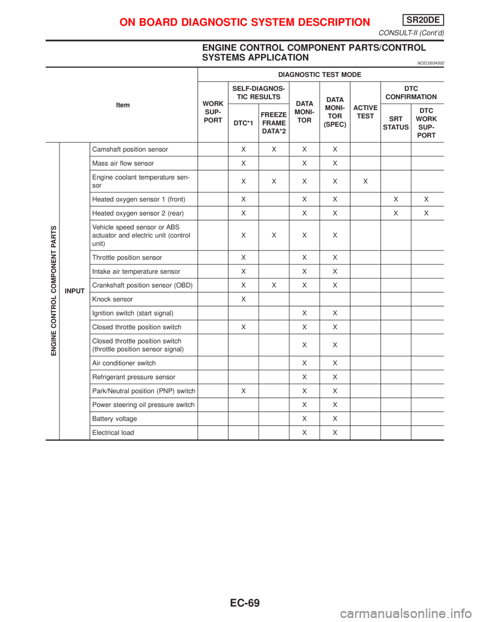
ENGINE CONTROL COMPONENT PARTS/CONTROL
SYSTEMS APPLICATION
NCEC0034S02
ItemDIAGNOSTIC TEST MODE
WORK
SUP-
PORTSELF-DIAGNOS-
TIC RESULTS
D ATA
MONI-
TORD ATA
MONI-
TOR
(SPEC)ACTIVE
TESTDTC
CONFIRMATION
DTC*1FREEZE
FRAME
DATA*2SRT
STATUSDTC
WORK
SUP-
PORT
ENGINE CONTROL COMPONENT PARTS
INPUTCamshaft position sensorXXXX
Mass air flow sensor X X X
Engine coolant temperature sen-
sorXXXXX
Heated oxygen sensor 1 (front) X X X X X
Heated oxygen sensor 2 (rear) X X X X X
Vehicle speed sensor or ABS
actuator and electric unit (control
unit)XXXX
Throttle position sensor X X X
Intake air temperature sensor X X X
Crankshaft position sensor (OBD)XXXX
Knock sensor X
Ignition switch (start signal) X X
Closed throttle position switch X X X
Closed throttle position switch
(throttle position sensor signal)XX
Air conditioner switch X X
Refrigerant pressure sensor X X
Park/Neutral position (PNP) switch X X X
Power steering oil pressure switch X X
Battery voltage X X
Electrical load X X
ON BOARD DIAGNOSTIC SYSTEM DESCRIPTIONSR20DE
CONSULT-II (Cont'd)
EC-69