1999 NISSAN PRIMERA bulb
[x] Cancel search: bulbPage 181 of 2267
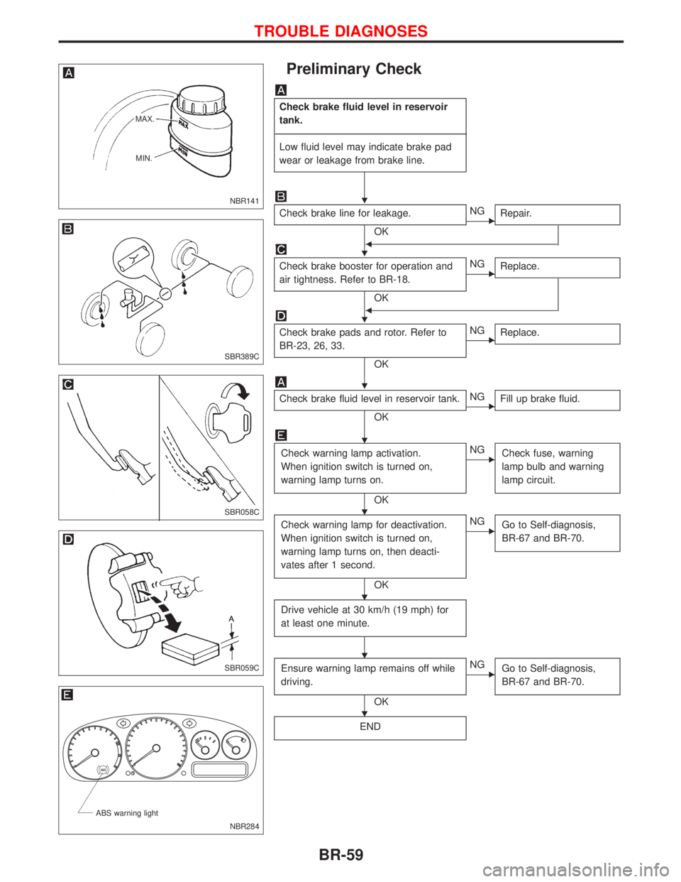
Preliminary Check
Check brake fluid level in reservoir
tank.
------------------------------------------------------------------------------------------------------------------------------------------------------------------------------------------------------------------------------------------------------------------------------------------------------------
Low fluid level may indicate brake pad
wear or leakage from brake line.
Check brake line for leakage.
OK
ENG
Repair.
F
Check brake booster for operation and
air tightness. Refer to BR-18.
OK
ENG
Replace.
F
Check brake pads and rotor. Refer to
BR-23, 26, 33.
OK
ENG
Replace.
Check brake fluid level in reservoir tank.
OK
ENG
Fill up brake fluid.
Check warning lamp activation.
When ignition switch is turned on,
warning lamp turns on.
OK
ENG
Check fuse, warning
lamp bulb and warning
lamp circuit.
Check warning lamp for deactivation.
When ignition switch is turned on,
warning lamp turns on, then deacti-
vates after 1 second.
OK
ENG
Go to Self-diagnosis,
BR-67 and BR-70.
Drive vehicle at 30 km/h (19 mph) for
at least one minute.
Ensure warning lamp remains off while
driving.
OK
ENG
Go to Self-diagnosis,
BR-67 and BR-70.
END
NBR141 MAX.
MIN.
SBR389C
SBR058C
SBR059C
.
NBR284 ABS warning light
H
H
H
H
H
H
H
H
H
TROUBLE DIAGNOSES
BR-59
Page 198 of 2267
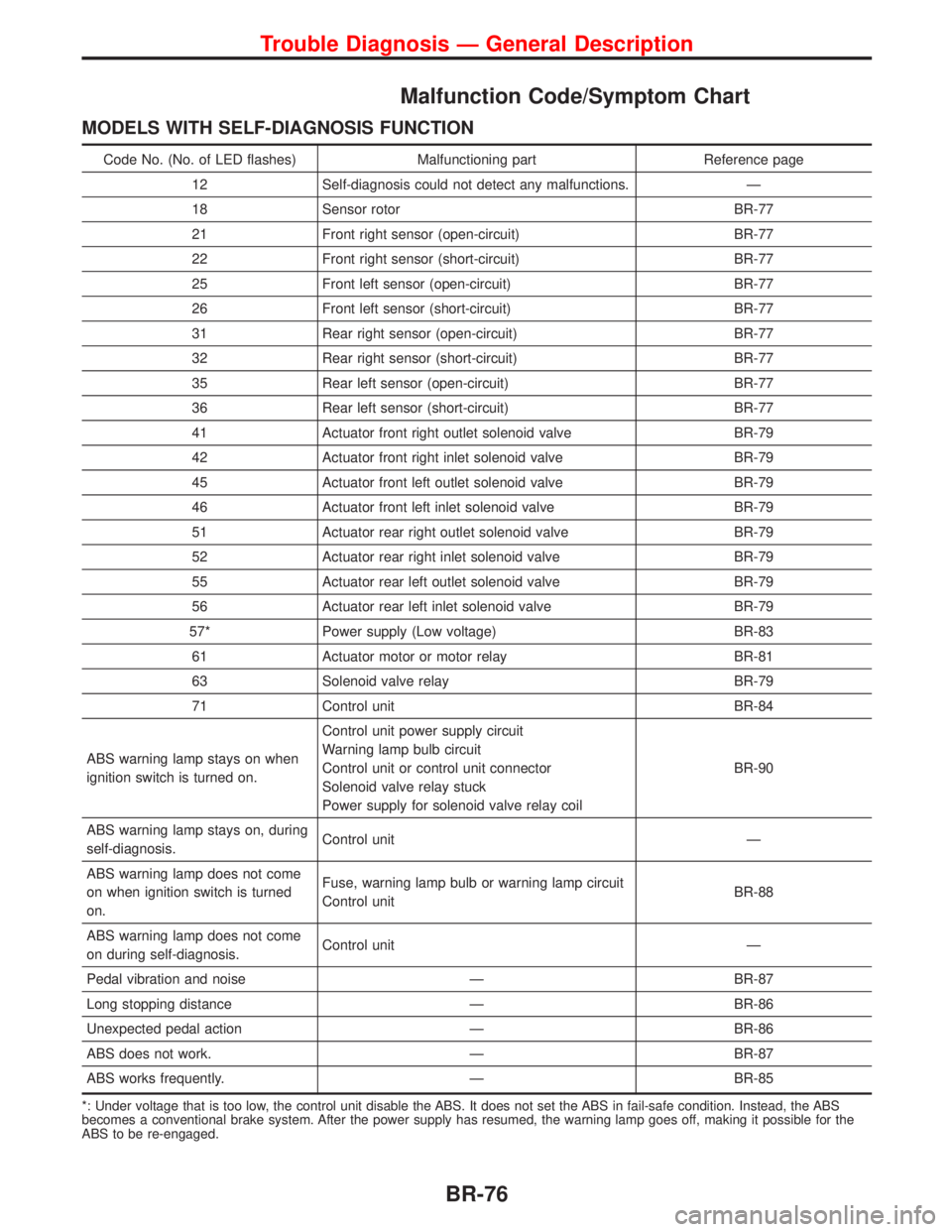
Malfunction Code/Symptom Chart
MODELS WITH SELF-DIAGNOSIS FUNCTION
Code No. (No. of LED flashes) Malfunctioning part Reference page
12 Self-diagnosis could not detect any malfunctions. Ð
18 Sensor rotor BR-77
21 Front right sensor (open-circuit) BR-77
22 Front right sensor (short-circuit) BR-77
25 Front left sensor (open-circuit) BR-77
26 Front left sensor (short-circuit) BR-77
31 Rear right sensor (open-circuit) BR-77
32 Rear right sensor (short-circuit) BR-77
35 Rear left sensor (open-circuit) BR-77
36 Rear left sensor (short-circuit) BR-77
41 Actuator front right outlet solenoid valve BR-79
42 Actuator front right inlet solenoid valve BR-79
45 Actuator front left outlet solenoid valve BR-79
46 Actuator front left inlet solenoid valve BR-79
51 Actuator rear right outlet solenoid valve BR-79
52 Actuator rear right inlet solenoid valve BR-79
55 Actuator rear left outlet solenoid valve BR-79
56 Actuator rear left inlet solenoid valve BR-79
57* Power supply (Low voltage) BR-83
61 Actuator motor or motor relay BR-81
63 Solenoid valve relay BR-79
71 Control unit BR-84
ABS warning lamp stays on when
ignition switch is turned on.Control unit power supply circuit
Warning lamp bulb circuit
Control unit or control unit connector
Solenoid valve relay stuck
Power supply for solenoid valve relay coilBR-90
ABS warning lamp stays on, during
self-diagnosis.Control unit Ð
ABS warning lamp does not come
on when ignition switch is turned
on.Fuse, warning lamp bulb or warning lamp circuit
Control unitBR-88
ABS warning lamp does not come
on during self-diagnosis.Control unit Ð
Pedal vibration and noise Ð BR-87
Long stopping distance Ð BR-86
Unexpected pedal action Ð BR-86
ABS does not work. Ð BR-87
ABS works frequently. Ð BR-85
*: Under voltage that is too low, the control unit disable the ABS. It does not set the ABS in fail-safe condition. Instead, the ABS
becomes a conventional brake system. After the power supply has resumed, the warning lamp goes off, making it possible for the
ABS to be re-engaged.
Trouble Diagnosis Ð General Description
BR-76
Page 437 of 2267
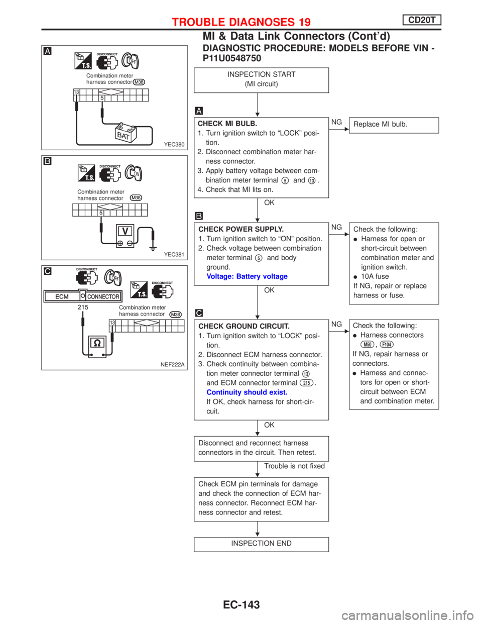
DIAGNOSTIC PROCEDURE: MODELS BEFORE VIN -
P11U0548750
INSPECTION START
(MI circuit)
CHECK MI BULB.
1. Turn ignition switch to ªLOCKº posi-
tion.
2. Disconnect combination meter har-
ness connector.
3. Apply battery voltage between com-
bination meter terminal
p5andp13.
4. Check that MI lits on.
OK
ENG
Replace MI bulb.
CHECK POWER SUPPLY.
1. Turn ignition switch to ªONº position.
2. Check voltage between combination
meter terminal
p5and body
ground.
Voltage: Battery voltage
OK
ENG
Check the following:
lHarness for open or
short-circuit between
combination meter and
ignition switch.
l10A fuse
If NG, repair or replace
harness or fuse.
CHECK GROUND CIRCUIT.
1. Turn ignition switch to ªLOCKº posi-
tion.
2. Disconnect ECM harness connector.
3. Check continuity between combina-
tion meter connector terminal
p13
and ECM connector terminal215.
Continuity should exist.
If OK, check harness for short-cir-
cuit.
OK
ENG
Check the following:
lHarness connectors
M50,F104
If NG, repair harness or
connectors.
lHarness and connec-
tors for open or short-
circuit between ECM
and combination meter.
Disconnect and reconnect harness
connectors in the circuit. Then retest.
Trouble is not fixed
Check ECM pin terminals for damage
and check the connection of ECM har-
ness connector. Reconnect ECM har-
ness connector and retest.
INSPECTION END
YEC380
Combination meter
harness connector
YEC381
Combination meter
harness connector
NEF222A
Combination meter
harness connector
H
H
H
H
H
H
TROUBLE DIAGNOSES 19CD20T
MI & Data Link Connectors (Cont'd)
EC-143
Page 488 of 2267
DESCRIPTIONNCEC0032
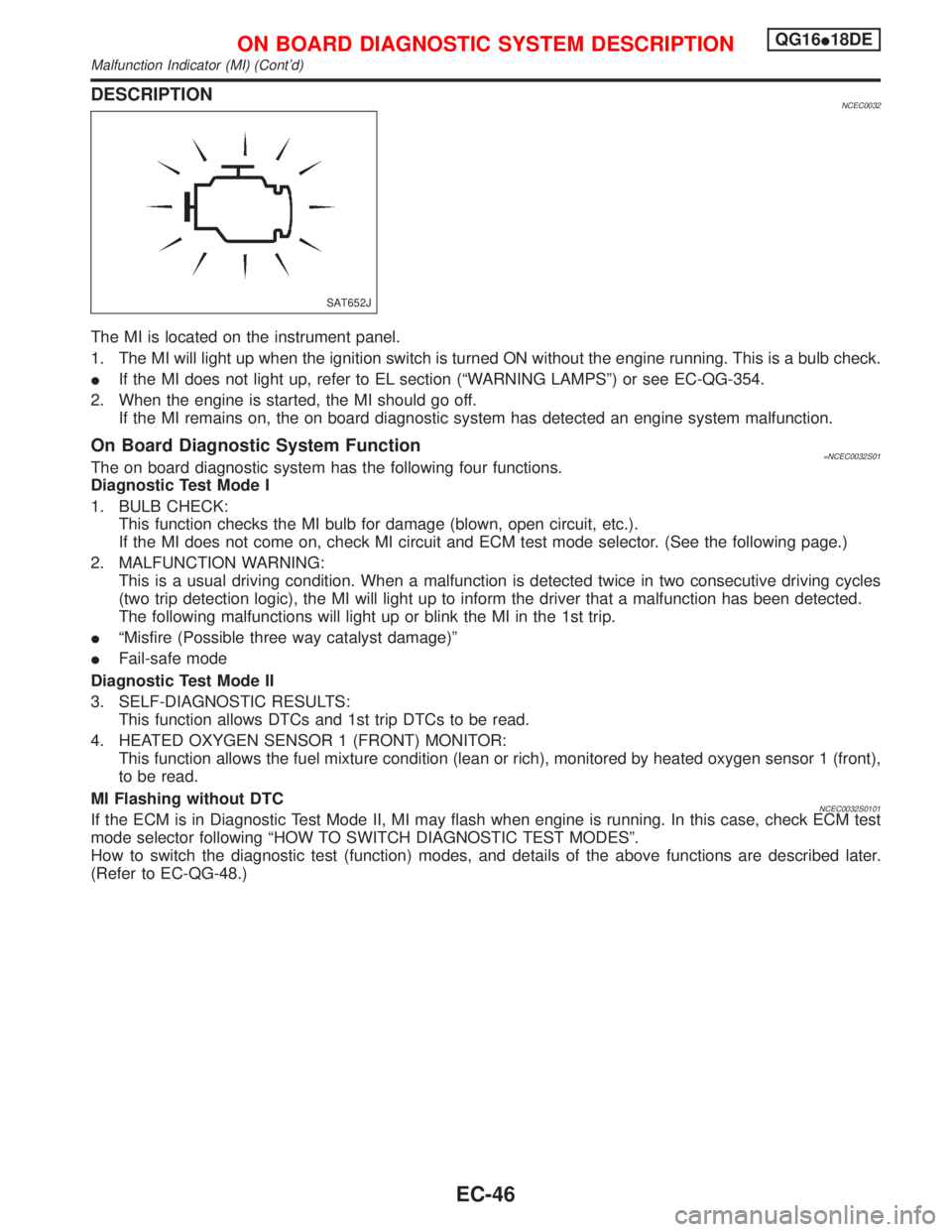
The MI is located on the instrument panel.
1. The MI will light up when the ignition switch is turned ON without the engine running. This is a bulb check.
IIf the MI does not light up, refer to EL section (ªWARNING LAMPSº) or see EC-QG-354.
2. When the engine is started, the MI should go off.
If the MI remains on, the on board diagnostic system has detected an engine system malfunction.
On Board Diagnostic System Function=NCEC0032S01The on board diagnostic system has the following four functions.
Diagnostic Test Mode I
1. BULB CHECK:
This function checks the MI bulb for damage (blown, open circuit, etc.).
If the MI does not come on, check MI circuit and ECM test mode selector. (See the following page.)
2. MALFUNCTION WARNING:
This is a usual driving condition. When a malfunction is detected twice in two consecutive driving cycles
(two trip detection logic), the MI will light up to inform the driver that a malfunction has been detected.
The following malfunctions will light up or blink the MI in the 1st trip.
IªMisfire (Possible three way catalyst damage)º
IFail-safe mode
Diagnostic Test Mode II
3. SELF-DIAGNOSTIC RESULTS:
This function allows DTCs and 1st trip DTCs to be read.
4. HEATED OXYGEN SENSOR 1 (FRONT) MONITOR:
This function allows the fuel mixture condition (lean or rich), monitored by heated oxygen sensor 1 (front),
to be read.
MI Flashing without DTC
NCEC0032S0101If the ECM is in Diagnostic Test Mode II, MI may flash when engine is running. In this case, check ECM test
mode selector following ªHOW TO SWITCH DIAGNOSTIC TEST MODESº.
How to switch the diagnostic test (function) modes, and details of the above functions are described later.
(Refer to EC-QG-48.)
SAT652J
ON BOARD DIAGNOSTIC SYSTEM DESCRIPTIONQG16I18DE
Malfunction Indicator (MI) (Cont'd)
EC-46
Page 489 of 2267
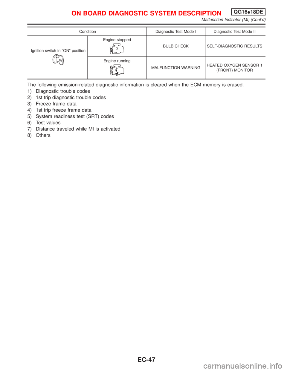
Condition Diagnostic Test Mode I Diagnostic Test Mode II
Ignition switch in ªONº position
Engine stopped
BULB CHECK SELF-DIAGNOSTIC RESULTS
Engine running
MALFUNCTION WARNINGHEATED OXYGEN SENSOR 1
(FRONT) MONITOR
The following emission-related diagnostic information is cleared when the ECM memory is erased.
1) Diagnostic trouble codes
2) 1st trip diagnostic trouble codes
3) Freeze frame data
4) 1st trip freeze frame data
5) System readiness test (SRT) codes
6) Test values
7) Distance traveled while MI is activated
8) Others
ON BOARD DIAGNOSTIC SYSTEM DESCRIPTIONQG16I18DE
Malfunction Indicator (MI) (Cont'd)
EC-47
Page 491 of 2267
Diagnostic Test Mode I Ð Bulb CheckNCEC0032S03In this mode, the MI on the instrument panel should stay ON. If it remains OFF, check the MI bulb. Refer to
EL section (ªWARNING LAMPSº) or see EC-QG-354.
Diagnostic Test Mode I Ð Malfunction WarningNCEC0032S04
MI Condition
ON When the malfunction is detected or the ECM's CPU is malfunctioning.
OFF No malfunction.
IThese DTC numbers are clarified in Diagnostic Test Mode II (SELF-DIAGNOSTIC RESULTS).
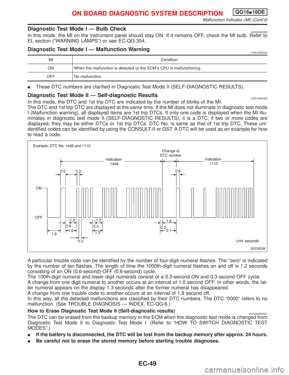
Diagnostic Test Mode II Ð Self-diagnostic ResultsNCEC0032S05In this mode, the DTC and 1st trip DTC are indicated by the number of blinks of the MI.
The DTC and 1st trip DTC are displayed at the same time. If the MI does not illuminate in diagnostic test mode
I (Malfunction warning), all displayed items are 1st trip DTCs. If only one code is displayed when the MI illu-
minates in diagnostic test mode II (SELF-DIAGNOSTIC RESULTS), it is a DTC; if two or more codes are
displayed, they may be either DTCs or 1st trip DTCs. DTC No. is same as that of 1st trip DTC. These uni-
dentified codes can be identified by using the CONSULT-II or GST. A DTC will be used as an example for how
to read a code.
A particular trouble code can be identified by the number of four-digit numeral flashes. The ªzeroº is indicated
by the number of ten flashes. The length of time the 1000th-digit numeral flashes on and off is 1.2 seconds
consisting of an ON (0.6-second)-OFF (0.6-second) cycle.
The 100th-digit numeral and lower digit numerals consist of a 0.3-second ON and 0.3-second OFF cycle.
A change from one digit numeral to another occurs at an interval of 1.0 second OFF. In other words, the lat-
ter numeral appears on the display 1.3 seconds after the former numeral has disappeared.
A change from one trouble code to another occurs at an interval of 1.8 second off.
In this way, all the detected malfunctions are classified by their DTC numbers. The DTC ª0000º refers to no
malfunction. (See TROUBLE DIAGNOSIS Ð INDEX, EC-QG-6.)
How to Erase Diagnostic Test Mode II (Self-diagnostic results)
NCEC0032S0501The DTC can be erased from the backup memory in the ECM when the diagnostic test mode is changed from
Diagnostic Test Mode II to Diagnostic Test Mode I. (Refer to ªHOW TO SWITCH DIAGNOSTIC TEST
MODESº.)
IIf the battery is disconnected, the DTC will be lost from the backup memory after approx. 24 hours.
IBe careful not to erase the stored memory before starting trouble diagnoses.
SEF952W
ON BOARD DIAGNOSTIC SYSTEM DESCRIPTIONQG16I18DE
Malfunction Indicator (MI) (Cont'd)
EC-49
Page 859 of 2267
DESCRIPTIONNCEC0032
The MI is located on the instrument panel.
1. The MI will light up when the ignition switch is turned ON without the engine running. This is a bulb check.
IIf the MI does not light up, refer to EL section (ªWARNING LAMPSº) or see EC-SR-329.
2. When the engine is started, the MI should go off.
If the MI remains on, the on board diagnostic system has detected an engine system malfunction.
On Board Diagnostic System FunctionNCEC0032S01The on board diagnostic system has the following four functions.
Diagnostic Test Mode I
1. BULB CHECK:
This function checks the MI bulb for damage (blown, open circuit, etc.).
If the MI does not come on, check MI circuit and ECM test mode selector. (See the following page.)
2. MALFUNCTION WARNING:
This is a usual driving condition. When a malfunction is detected twice in two consecutive driving cycles
(two trip detection logic), the MI will light up to inform the driver that a malfunction has been detected.
The following malfunctions will light up or blink the MI in the 1st trip.
IªMisfire (Possible three way catalyst damage)º
IªClosed loop controlº
IFail-safe mode
Diagnostic Test Mode II
3. SELF-DIAGNOSTIC RESULTS:
This function allows DTCs and 1st trip DTCs to be read.
4. HEATED OXYGEN SENSOR 1 (FRONT) MONITOR:
This function allows the fuel mixture condition (lean or rich), monitored by heated oxygen sensor 1 (front),
to be read.
MI Flashing without DTC
NCEC0032S0101If the ECM is in Diagnostic Test Mode II, MI may flash when engine is running. In this case, check ECM test
mode following ªHOW TO SWITCH DIAGNOSTIC TEST MODESº.
How to switch the diagnostic test (function) modes, and details of the above functions are described later.
(Refer to EC-SR-61.)
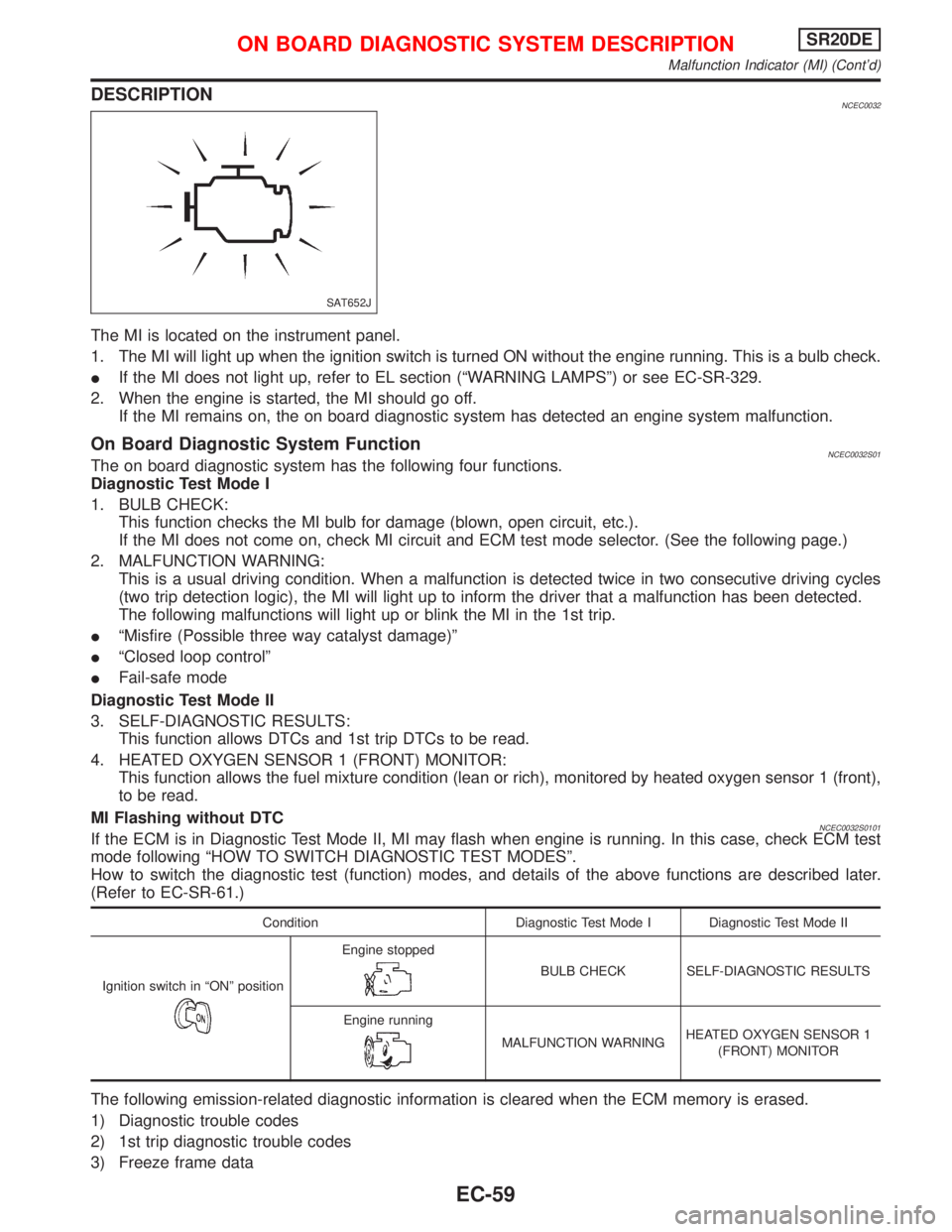
Condition Diagnostic Test Mode I Diagnostic Test Mode II
Ignition switch in ªONº position
Engine stopped
BULB CHECK SELF-DIAGNOSTIC RESULTS
Engine running
MALFUNCTION WARNINGHEATED OXYGEN SENSOR 1
(FRONT) MONITOR
The following emission-related diagnostic information is cleared when the ECM memory is erased.
1) Diagnostic trouble codes
2) 1st trip diagnostic trouble codes
3) Freeze frame data
SAT652J
ON BOARD DIAGNOSTIC SYSTEM DESCRIPTIONSR20DE
Malfunction Indicator (MI) (Cont'd)
EC-59
Page 862 of 2267
Diagnostic Test Mode I Ð Bulb CheckNCEC0032S03In this mode, the MI on the instrument panel should stay ON. If it remains OFF, check the MI bulb. Refer to
EL section (ªWARNING LAMPSº) or see EC-SR-329.
Diagnostic Test Mode I Ð Malfunction WarningNCEC0032S04
MI Condition
ON When the malfunction is detected or the ECM's CPU is malfunctioning.
OFF No malfunction.
IThese DTC numbers are clarified in Diagnostic Test Mode II (SELF-DIAGNOSTIC RESULTS).
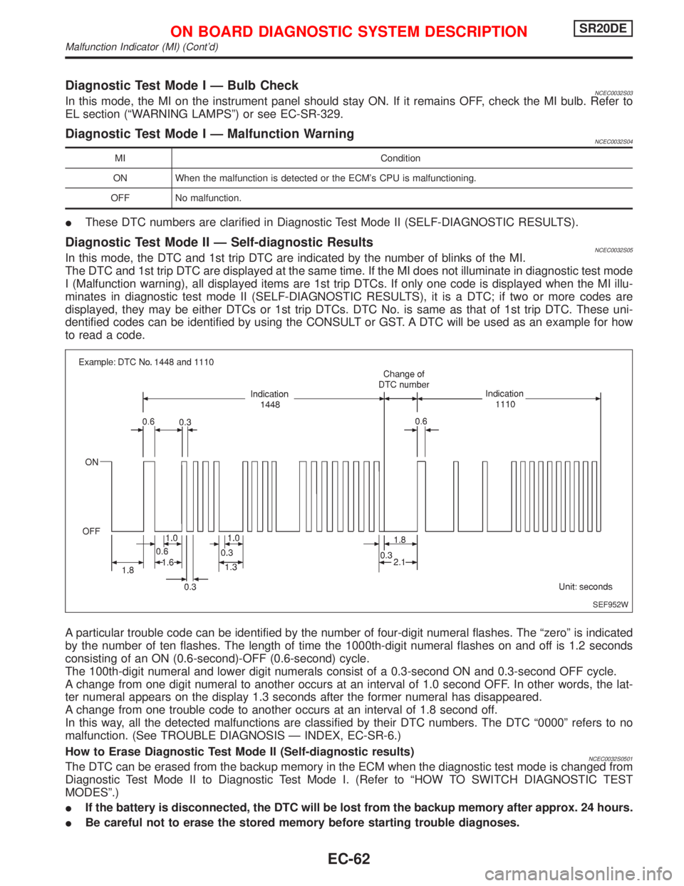
Diagnostic Test Mode II Ð Self-diagnostic ResultsNCEC0032S05In this mode, the DTC and 1st trip DTC are indicated by the number of blinks of the MI.
The DTC and 1st trip DTC are displayed at the same time. If the MI does not illuminate in diagnostic test mode
I (Malfunction warning), all displayed items are 1st trip DTCs. If only one code is displayed when the MI illu-
minates in diagnostic test mode II (SELF-DIAGNOSTIC RESULTS), it is a DTC; if two or more codes are
displayed, they may be either DTCs or 1st trip DTCs. DTC No. is same as that of 1st trip DTC. These uni-
dentified codes can be identified by using the CONSULT or GST. A DTC will be used as an example for how
to read a code.
A particular trouble code can be identified by the number of four-digit numeral flashes. The ªzeroº is indicated
by the number of ten flashes. The length of time the 1000th-digit numeral flashes on and off is 1.2 seconds
consisting of an ON (0.6-second)-OFF (0.6-second) cycle.
The 100th-digit numeral and lower digit numerals consist of a 0.3-second ON and 0.3-second OFF cycle.
A change from one digit numeral to another occurs at an interval of 1.0 second OFF. In other words, the lat-
ter numeral appears on the display 1.3 seconds after the former numeral has disappeared.
A change from one trouble code to another occurs at an interval of 1.8 second off.
In this way, all the detected malfunctions are classified by their DTC numbers. The DTC ª0000º refers to no
malfunction. (See TROUBLE DIAGNOSIS Ð INDEX, EC-SR-6.)
How to Erase Diagnostic Test Mode II (Self-diagnostic results)
NCEC0032S0501The DTC can be erased from the backup memory in the ECM when the diagnostic test mode is changed from
Diagnostic Test Mode II to Diagnostic Test Mode I. (Refer to ªHOW TO SWITCH DIAGNOSTIC TEST
MODESº.)
IIf the battery is disconnected, the DTC will be lost from the backup memory after approx. 24 hours.
IBe careful not to erase the stored memory before starting trouble diagnoses.
SEF952W
ON BOARD DIAGNOSTIC SYSTEM DESCRIPTIONSR20DE
Malfunction Indicator (MI) (Cont'd)
EC-62