1999 NISSAN PRIMERA fuel cap
[x] Cancel search: fuel capPage 316 of 2267
CAUTION:
lDo not disassemble injection nozzle assembly. Entrust
disassembly or adjustment to BOSCH service shop.
lPlug flare nut with a cap or rag so that no dust enters the
nozzle.
Removal and Installation
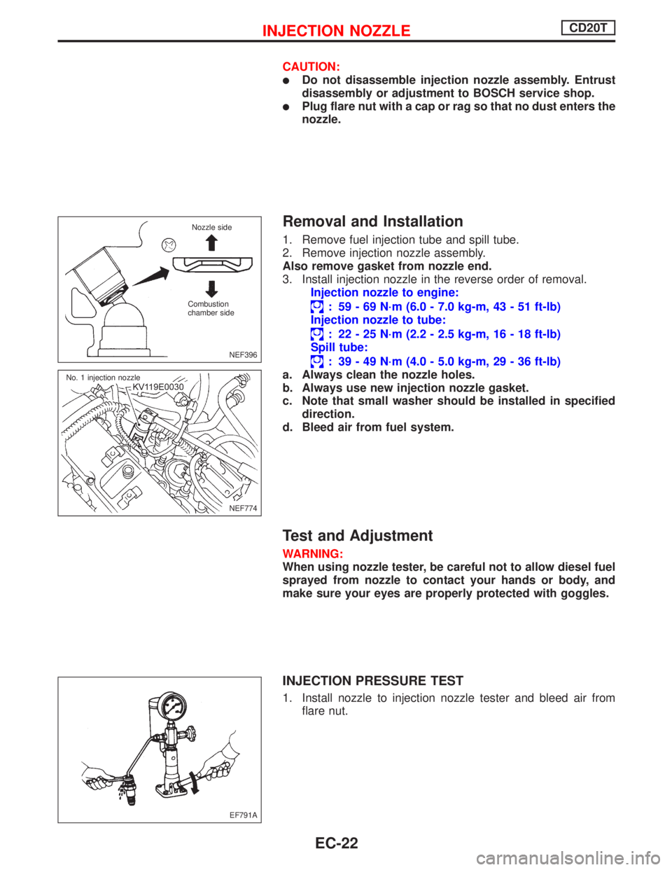
1. Remove fuel injection tube and spill tube.
2. Remove injection nozzle assembly.
Also remove gasket from nozzle end.
3. Install injection nozzle in the reverse order of removal.
Injection nozzle to engine:
: 59 - 69 N´m (6.0 - 7.0 kg-m, 43 - 51 ft-lb)
Injection nozzle to tube:
: 22 - 25 N´m (2.2 - 2.5 kg-m, 16 - 18 ft-lb)
Spill tube:
: 39 - 49 N´m (4.0 - 5.0 kg-m, 29 - 36 ft-lb)
a. Always clean the nozzle holes.
b. Always use new injection nozzle gasket.
c. Note that small washer should be installed in specified
direction.
d. Bleed air from fuel system.
Test and Adjustment
WARNING:
When using nozzle tester, be careful not to allow diesel fuel
sprayed from nozzle to contact your hands or body, and
make sure your eyes are properly protected with goggles.
INJECTION PRESSURE TEST
1. Install nozzle to injection nozzle tester and bleed air from
flare nut.
NEF396
Nozzle side
Combustion
chamber side
NEF774 No. 1 injection nozzle
EF791A
INJECTION NOZZLECD20T
EC-22
Page 336 of 2267
Ð: Not applicable
Check Items
(Possible Cause)*1
Confirmation
Procedure
Quick Ref.*2
Overall
Function
CheckMI
IlluminationReference
Page
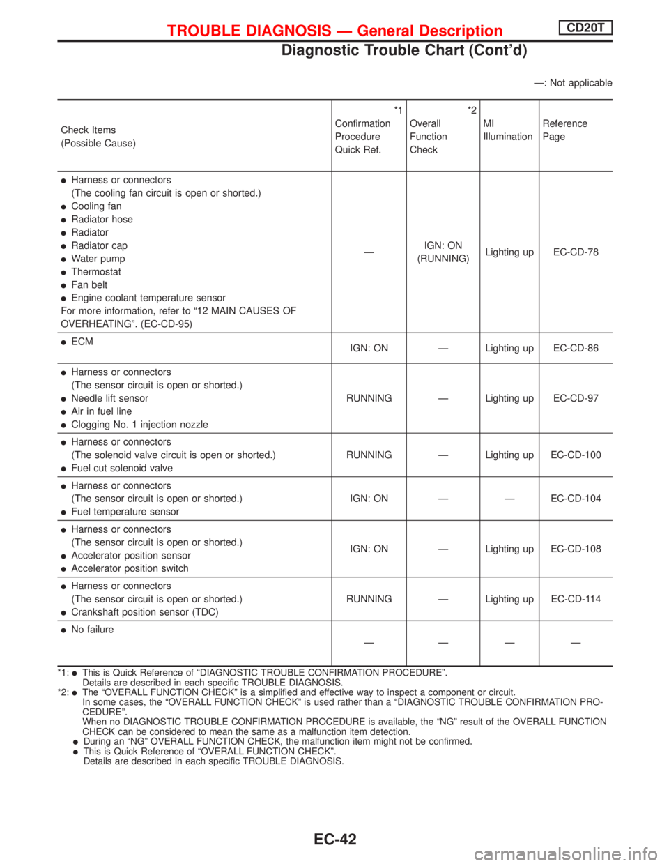
lHarness or connectors
(The cooling fan circuit is open or shorted.)
lCooling fan
lRadiator hose
lRadiator
lRadiator cap
lWater pump
lThermostat
lFan belt
lEngine coolant temperature sensor
For more information, refer to ª12 MAIN CAUSES OF
OVERHEATINGº. (EC-CD-95)ÐIGN: ON
(RUNNING)Lighting up EC-CD-78
lECM
IGN: ON Ð Lighting up EC-CD-86
lHarness or connectors
(The sensor circuit is open or shorted.)
lNeedle lift sensor
lAir in fuel line
lClogging No. 1 injection nozzleRUNNING Ð Lighting up EC-CD-97
lHarness or connectors
(The solenoid valve circuit is open or shorted.)
lFuel cut solenoid valveRUNNING Ð Lighting up EC-CD-100
lHarness or connectors
(The sensor circuit is open or shorted.)
lFuel temperature sensorIGN: ON Ð Ð EC-CD-104
lHarness or connectors
(The sensor circuit is open or shorted.)
lAccelerator position sensor
lAccelerator position switchIGN: ON Ð Lighting up EC-CD-108
lHarness or connectors
(The sensor circuit is open or shorted.)
lCrankshaft position sensor (TDC)RUNNING Ð Lighting up EC-CD-114
lNo failure
Ð ÐÐÐ
*1:lThis is Quick Reference of ªDIAGNOSTIC TROUBLE CONFIRMATION PROCEDUREº.
Details are described in each specific TROUBLE DIAGNOSIS.
*2:
lThe ªOVERALL FUNCTION CHECKº is a simplified and effective way to inspect a component or circuit.
In some cases, the ªOVERALL FUNCTION CHECKº is used rather than a ªDIAGNOSTIC TROUBLE CONFIRMATION PRO-
CEDUREº.
When no DIAGNOSTIC TROUBLE CONFIRMATION PROCEDURE is available, the ªNGº result of the OVERALL FUNCTION
CHECK can be considered to mean the same as a malfunction item detection.
lDuring an ªNGº OVERALL FUNCTION CHECK, the malfunction item might not be confirmed.lThis is Quick Reference of ªOVERALL FUNCTION CHECKº.
Details are described in each specific TROUBLE DIAGNOSIS.
TROUBLE DIAGNOSIS Ð General DescriptionCD20T
Diagnostic Trouble Chart (Cont'd)
EC-42
Page 455 of 2267
Special Service ToolsNCEC0007
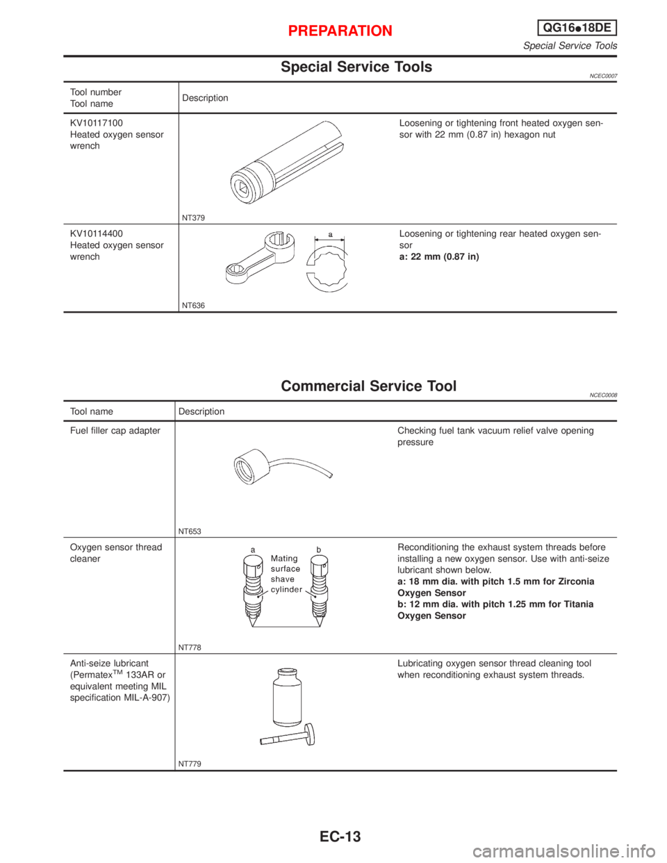
Tool number
Tool nameDescription
KV10117100
Heated oxygen sensor
wrench
NT379
Loosening or tightening front heated oxygen sen-
sor with 22 mm (0.87 in) hexagon nut
KV10114400
Heated oxygen sensor
wrench
NT636
Loosening or tightening rear heated oxygen sen-
sor
a: 22 mm (0.87 in)
Commercial Service ToolNCEC0008
Tool name Description
Fuel filler cap adapter
NT653
Checking fuel tank vacuum relief valve opening
pressure
Oxygen sensor thread
cleaner
NT778
Reconditioning the exhaust system threads before
installing a new oxygen sensor. Use with anti-seize
lubricant shown below.
a: 18 mm dia. with pitch 1.5 mm for Zirconia
Oxygen Sensor
b: 12 mm dia. with pitch 1.25 mm for Titania
Oxygen Sensor
Anti-seize lubricant
(Permatex
TM133AR or
equivalent meeting MIL
specification MIL-A-907)
NT779
Lubricating oxygen sensor thread cleaning tool
when reconditioning exhaust system threads.
PREPARATIONQG16I18DE
Special Service Tools
EC-13
Page 468 of 2267
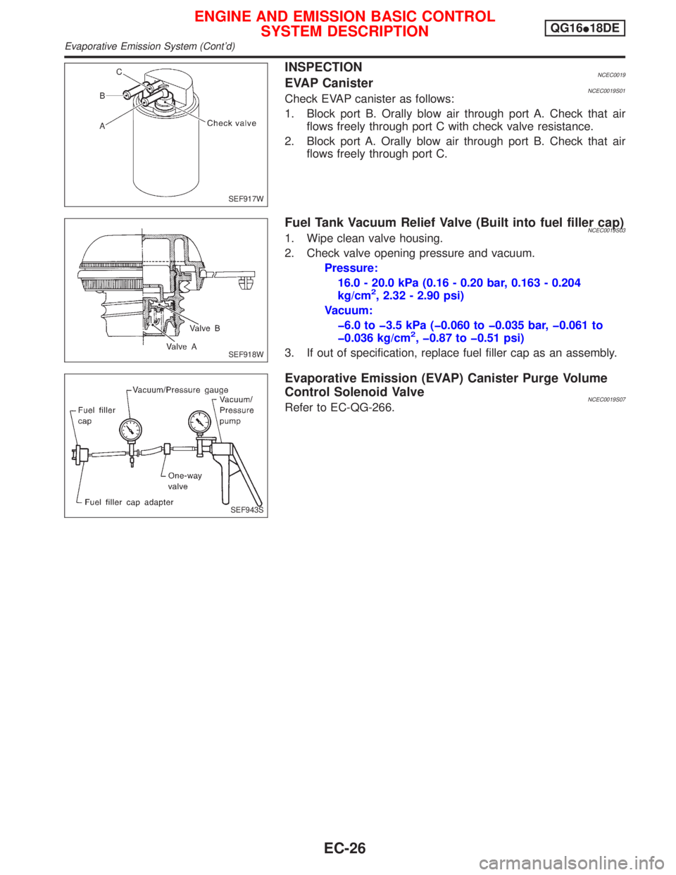
INSPECTIONNCEC0019EVAP CanisterNCEC0019S01Check EVAP canister as follows:
1. Block port B. Orally blow air through port A. Check that air
flows freely through port C with check valve resistance.
2. Block port A. Orally blow air through port B. Check that air
flows freely through port C.
Fuel Tank Vacuum Relief Valve (Built into fuel filler cap)NCEC0019S031. Wipe clean valve housing.
2. Check valve opening pressure and vacuum.
Pressure:
16.0 - 20.0 kPa (0.16 - 0.20 bar, 0.163 - 0.204
kg/cm
2, 2.32 - 2.90 psi)
Vacuum:
þ6.0 to þ3.5 kPa (þ0.060 to þ0.035 bar, þ0.061 to
þ0.036 kg/cm
2, þ0.87 to þ0.51 psi)
3. If out of specification, replace fuel filler cap as an assembly.
Evaporative Emission (EVAP) Canister Purge Volume
Control Solenoid Valve
NCEC0019S07Refer to EC-QG-266.
SEF917W
SEF918W
SEF943S
ENGINE AND EMISSION BASIC CONTROL
SYSTEM DESCRIPTIONQG16I18DE
Evaporative Emission System (Cont'd)
EC-26
Page 472 of 2267
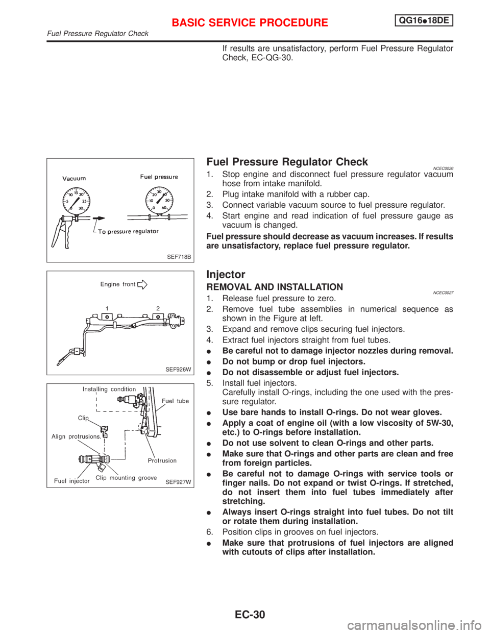
If results are unsatisfactory, perform Fuel Pressure Regulator
Check, EC-QG-30.
Fuel Pressure Regulator CheckNCEC00261. Stop engine and disconnect fuel pressure regulator vacuum
hose from intake manifold.
2. Plug intake manifold with a rubber cap.
3. Connect variable vacuum source to fuel pressure regulator.
4. Start engine and read indication of fuel pressure gauge as
vacuum is changed.
Fuel pressure should decrease as vacuum increases. If results
are unsatisfactory, replace fuel pressure regulator.
Injector
REMOVAL AND INSTALLATIONNCEC00271. Release fuel pressure to zero.
2. Remove fuel tube assemblies in numerical sequence as
shown in the Figure at left.
3. Expand and remove clips securing fuel injectors.
4. Extract fuel injectors straight from fuel tubes.
IBe careful not to damage injector nozzles during removal.
IDo not bump or drop fuel injectors.
IDo not disassemble or adjust fuel injectors.
5. Install fuel injectors.
Carefully install O-rings, including the one used with the pres-
sure regulator.
IUse bare hands to install O-rings. Do not wear gloves.
IApply a coat of engine oil (with a low viscosity of 5W-30,
etc.) to O-rings before installation.
IDo not use solvent to clean O-rings and other parts.
IMake sure that O-rings and other parts are clean and free
from foreign particles.
IBe careful not to damage O-rings with service tools or
finger nails. Do not expand or twist O-rings. If stretched,
do not insert them into fuel tubes immediately after
stretching.
IAlways insert O-rings straight into fuel tubes. Do not tilt
or rotate them during installation.
6. Position clips in grooves on fuel injectors.
IMake sure that protrusions of fuel injectors are aligned
with cutouts of clips after installation.
SEF718B
SEF926W
SEF927W
BASIC SERVICE PROCEDUREQG16I18DE
Fuel Pressure Regulator Check
EC-30
Page 527 of 2267
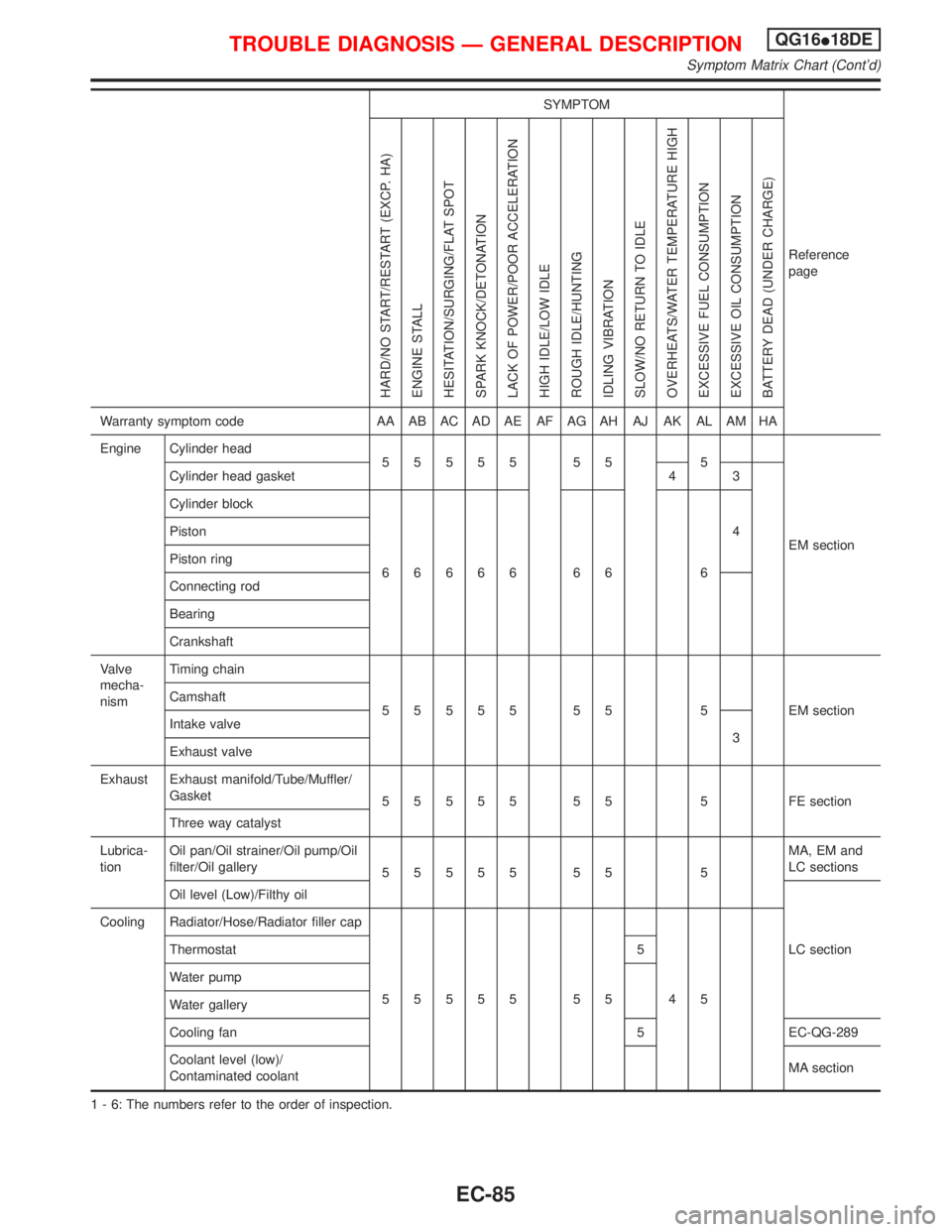
SYMPTOM
Reference
page
HARD/NO START/RESTART (EXCP. HA)
ENGINE STALL
HESITATION/SURGING/FLAT SPOT
SPARK KNOCK/DETONATION
LACK OF POWER/POOR ACCELERATION
HIGH IDLE/LOW IDLE
ROUGH IDLE/HUNTING
IDLING VIBRATION
SLOW/NO RETURN TO IDLE
OVERHEATS/WATER TEMPERATURE HIGH
EXCESSIVE FUEL CONSUMPTION
EXCESSIVE OIL CONSUMPTION
BATTERY DEAD (UNDER CHARGE)
Warranty symptom code AA AB AC AD AE AF AG AH AJ AK AL AM HA
Engine Cylinder head
55555 55 5
EM section Cylinder head gasket 4 3
Cylinder block
66666 66 64 Piston
Piston ring
Connecting rod
Bearing
Crankshaft
Valve
mecha-
nismTiming chain
55555 55 5 EMsection Camshaft
Intake valve
3
Exhaust valve
Exhaust Exhaust manifold/Tube/Muffler/
Gasket
55555 55 5 FEsection
Three way catalyst
Lubrica-
tionOil pan/Oil strainer/Oil pump/Oil
filter/Oil gallery
55555 55 5MA, EM and
LC sections
Oil level (Low)/Filthy oil
LC section Cooling Radiator/Hose/Radiator filler cap
55555 55 45 Thermostat 5
Water pump
Water gallery
Cooling fan 5 EC-QG-289
Coolant level (low)/
Contaminated coolantMA section
1 - 6: The numbers refer to the order of inspection.
TROUBLE DIAGNOSIS Ð GENERAL DESCRIPTIONQG16I18DE
Symptom Matrix Chart (Cont'd)
EC-85
Page 613 of 2267
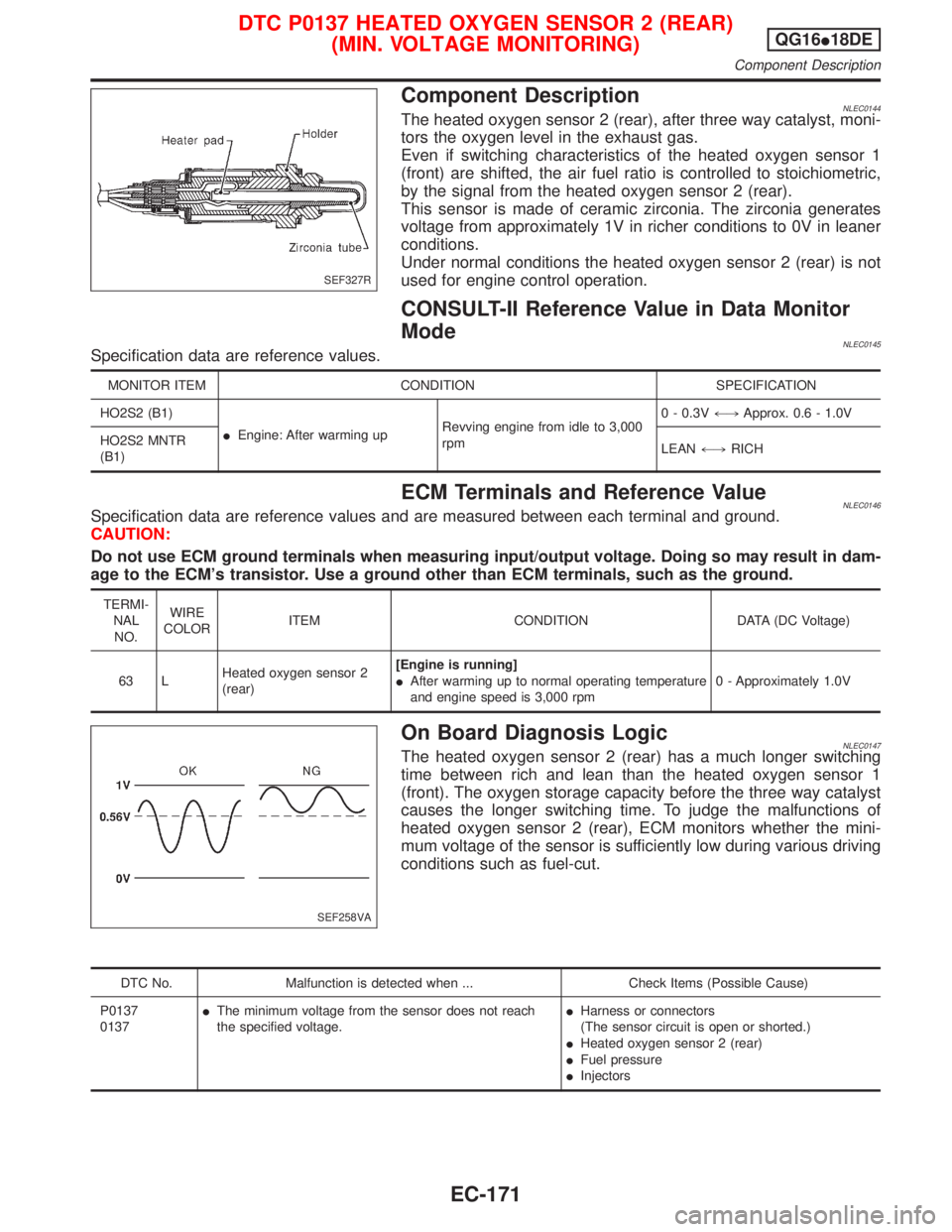
Component DescriptionNLEC0144The heated oxygen sensor 2 (rear), after three way catalyst, moni-
tors the oxygen level in the exhaust gas.
Even if switching characteristics of the heated oxygen sensor 1
(front) are shifted, the air fuel ratio is controlled to stoichiometric,
by the signal from the heated oxygen sensor 2 (rear).
This sensor is made of ceramic zirconia. The zirconia generates
voltage from approximately 1V in richer conditions to 0V in leaner
conditions.
Under normal conditions the heated oxygen sensor 2 (rear) is not
used for engine control operation.
CONSULT-II Reference Value in Data Monitor
Mode
NLEC0145Specification data are reference values.
MONITOR ITEM CONDITION SPECIFICATION
HO2S2 (B1)
IEngine: After warming upRevving engine from idle to 3,000
rpm0 - 0.3V+,Approx. 0.6 - 1.0V
HO2S2 MNTR
(B1)LEAN+,RICH
ECM Terminals and Reference ValueNLEC0146Specification data are reference values and are measured between each terminal and ground.
CAUTION:
Do not use ECM ground terminals when measuring input/output voltage. Doing so may result in dam-
age to the ECM's transistor. Use a ground other than ECM terminals, such as the ground.
TERMI-
NAL
NO.WIRE
COLORITEM CONDITION DATA (DC Voltage)
63 LHeated oxygen sensor 2
(rear)[Engine is running]
IAfter warming up to normal operating temperature
and engine speed is 3,000 rpm0 - Approximately 1.0V
On Board Diagnosis LogicNLEC0147The heated oxygen sensor 2 (rear) has a much longer switching
time between rich and lean than the heated oxygen sensor 1
(front). The oxygen storage capacity before the three way catalyst
causes the longer switching time. To judge the malfunctions of
heated oxygen sensor 2 (rear), ECM monitors whether the mini-
mum voltage of the sensor is sufficiently low during various driving
conditions such as fuel-cut.
DTC No. Malfunction is detected when ... Check Items (Possible Cause)
P0137
0137IThe minimum voltage from the sensor does not reach
the specified voltage.IHarness or connectors
(The sensor circuit is open or shorted.)
IHeated oxygen sensor 2 (rear)
IFuel pressure
IInjectors
SEF327R
SEF258VA
DTC P0137 HEATED OXYGEN SENSOR 2 (REAR)
(MIN. VOLTAGE MONITORING)QG16I18DE
Component Description
EC-171
Page 622 of 2267
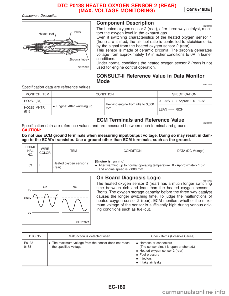
Component DescriptionNLEC0153The heated oxygen sensor 2 (rear), after three way catalyst, moni-
tors the oxygen level in the exhaust gas.
Even if switching characteristics of the heated oxygen sensor 1
(front) are shifted, the air fuel ratio is controlled to stoichiometric,
by the signal from the heated oxygen sensor 2 (rear).
This sensor is made of ceramic zirconia. The zirconia generates
voltage from approximately 1V in richer conditions to 0V in leaner
conditions.
Under normal conditions the heated oxygen sensor 2 (rear) is not
used for engine control operation.
CONSULT-II Reference Value in Data Monitor
Mode
NLEC0154Specification data are reference values.
MONITOR ITEM CONDITION SPECIFICATION
HO2S2 (B1)
IEngine: After warming upRevving engine from idle to 3,000
rpm0 - 0.3V+,Approx. 0.6 - 1.0V
HO2S2 MNTR
(B1)LEAN+,RICH
ECM Terminals and Reference ValueNLEC0155Specification data are reference values and are measured between each terminal and ground.
CAUTION:
Do not use ECM ground terminals when measuring input/output voltage. Doing so may result in dam-
age to the ECM's transistor. Use a ground other than ECM terminals, such as the ground.
TERMI-
NAL
NO.WIRE
COLORITEM CONDITION DATA (DC Voltage)
63 LHeated oxygen sensor 2
(rear)[Engine is running]
IAfter warming up to normal operating temperature
and engine speed is 2,000 rpm0 - Approximately 1.0V
On Board Diagnosis LogicNLEC0156The heated oxygen sensor 2 (rear) has a much longer switching
time between rich and lean than the heated oxygen sensor 1
(front). The oxygen storage capacity before the three way catalyst
causes the longer switching time. To judge the malfunctions of
heated oxygen sensor 2 (rear), ECM monitors whether the maxi-
mum voltage of the sensor is sufficiently high during various driv-
ing conditions such as fuel-cut.
DTC No. Malfunction is detected when ... Check Items (Possible Cause)
P0138
0138IThe maximum voltage from the sensor does not reach
the specified voltage.IHarness or connectors
(The sensor circuit is open or shorted.)
IHeated oxygen sensor 2 (rear)
IFuel pressure
IInjectors
IIntake air leaks
SEF327R
SEF259VA
DTC P0138 HEATED OXYGEN SENSOR 2 (REAR)
(MAX. VOLTAGE MONITORING)QG16I18DE
Component Description
EC-180