Page 1208 of 2267

Bulb Replacement
CAUTION:
�After replacing a new xenon bulb, be sure to make aim-
ing adjustments.
�Hold only the plastic base when handling the bulb. Never
touch the glass envelope.
�Do not leave headlamp reflector without bulb for a long
period of time. Dust, moisture, smoke, etc. entering
headlamp body may affect the performance of the head-
lamp. Remove headlamp bulb from the headlamp reflec-
tor just before a replacement bulb is installed.
1. Disconnect negative battery cable.
2. Remove side combination lamp and radiator grille.
3. Disconnect headlamp connector.
4. Remove headlamp assembly.
WARNING:
Never service a xenon headlamp with wet hands.
XENON BULB (LOW BEAM)
1. Remove headlamp seal cover.
2. Turn bulb socket counterclockwise with keep pushing, then
remove it.
3. Release retaining pin.
4. Remove the xenon bulb.
5. Install in the reverse order of removal.
CAUTION:
�When disposing of the xenon bulb, do not break it;
always dispose of it as is.
�Make sure to install the bulb securely; if the xenon bulb
is improperly installed in its socket, high-tension current
leaks occur. This may lead to a melted bulb and/or bulb
socket.
NEL765
.Bulb Socket
NEL551 Retaining pin
HEADLAMP (without Daytime Light System)—Xenon Type—
EL-76
Page 1209 of 2267
HIGH BEAM
1. Pull off headlamp seal cover.
2. Disconnect bulb connector.
3. Release retaining pin.
4. Remove the bulb.
5. Install in the reverse order of removal.
NEL564
.Seal cover
Retaining pin
HEADLAMP (without Daytime Light System)—Xenon Type—
Bulb Replacement (Cont’d)
EL-77
Page 1218 of 2267
/
OUTPUT (O)Operated conditionVoltage (V)
(Approximate
values)
1Power source for illumination & tail
lamp")
Trouble Diagnoses
DAYTIME LIGHT CONTROL UNIT INSPECTION TABLE
Terminal No. ConnectionsINPUT (I)/
OUTPUT (O)Operated conditionVoltage (V)
(Approximate
values)
1Power source for illumination & tail
lamp——12
2 Alternator“L”terminal I EngineRunning 12
Stopped 0
3 Lighting switch I1ST⋅2ND position 12
OFF 0
5 Power source for headlamp RH——12
6 Illumination & tail lamp OON (daytime light operating*) 12
OFF 0
7 Power source for headlamp LH——12
8 Start signal I Ignition switchSTART 12
ON, ACC or
OFF0
9Headlamp LH (conventional type),
Headlamp relay LH (xenon type)OON (daytime light operating*) 12
OFF 0
10 Ground———
11Headlamp RH (conventional type),
Headlamp relay RH (xenon type)OON (daytime light operating*) 12
OFF 0
12 Power source—Ignition switchON or START 12
ACC or OFF 0
*: Daytime light operating: Lighting switch in“OFF”position with engine running.
Bulb Replacement/Conventional Type
For bulb replacement refer to EL-70.
Bulb specifications/Conventional Type
For bulb specifications, refer to EL-137.
Aiming Adjustment/Conventional Type
For aiming adjustment, refer to EL-70.
Bulb replacement/Xenon Type
For bulb replacement, refer to EL-76.
Aiming Adjustment/Xenon Type
For aiming adjustment, refer to EL-91.
HEADLAMP—Daytime Light System—
EL-86
Page 1227 of 2267
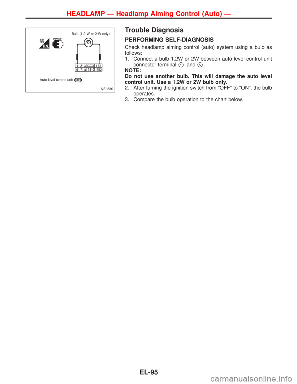
Trouble Diagnosis
PERFORMING SELF-DIAGNOSIS
Check headlamp aiming control (auto) system using a bulb as
follows:
1. Connect a bulb 1.2W or 2W between auto level control unit
connector terminal
�1and�5.
NOTE:
Do not use another bulb. This will damage the auto level
control unit. Use a 1.2W or 2W bulb only.
2. After turning the ignition switch from“OFF”to“ON”, the bulb
operates.
3. Compare the bulb operation to the chart below.
NEL530
Auto level control unitBulb (1.2 W or 2 W only)
HEADLAMP—Headlamp Aiming Control (Auto)—
EL-95
Page 1228 of 2267
Lighting condition of the bulb System condition Reference item
NEL531 IGN ON
ON
OFF1 sec.
No malfunction is detected.
No further action is neces-
sary.
—
NEL532 IGN ON
ON
OFF1 sec.2 sec. 2 sec.
0.5 sec.
Front sensor or front sensor
circuit is malfunctioning.
(When rear sensor OK)Go to DIAGNOSTIC
PROCEDURE 1
(EL-97).
NEL533 IGN ON
ON
OFF1 sec.2 sec. 2 sec.
0.5 sec. 0.5 sec.
Rear sensor or rear sensor
circuit is malfunctioning.
(Whatever the state of front
sensor)Go to DIAGNOSTIC
PROCEDURE 2
(EL-97).
NEL534 IGN ON
ON
OFF1 sec.2 sec. 2 sec.
0.5 sec. 0.5 sec.
Sensor supply is malfunction-
ing.Go to DIAGNOSTIC
PROCEDURE 1 and
2 (EL-97).
NEL535 IGN ON
ON
OFF1 sec.2 sec. 2 sec.
0.5 sec. 0.5 sec.
Aiming motor or aiming motor
circuit is malfunctioning.Go to DIAGNOSTIC
PROCEDURE 3
(EL-98).
NEL536 IGN ON
ON
OFF
Auto level control unit is mal-
functioning.Replace auto level
control unit.
HEADLAMP—Headlamp Aiming Control (Auto)—
Trouble Diagnosis (Cont’d)
EL-96
Page 1243 of 2267

Aiming Adjustment
Before performing aiming adjustment, make sure of the follow-
ing.
a. Keep all tires inflated to correct pressure.
b. Place vehicle on level ground.
c. Check that vehicle is unloaded (except for full levels of
coolant, engine oil and fuel, and spare tire, jack, and tools).
Have the driver or equivalent weight placed in driver’s seat.
1. Set the distance between the screen and the center of the
fog lamp lens as shown at left.
2. Turn front fog lamps ON.
3. Adjust front fog lamps so that the top edge of the high inten-
sity zone is 100 mm (4 in) below the height of the fog lamp
centers as shown at left.
�When performing adjustment, if necessary, cover the head-
lamps and opposite fog lamp.
Bulb Specifications
Item Wattage (W)
Front fog lamp 55
NEL553 Aiming adjusting screw
MEL327G
7.6 m (25 ft)
Screen
Main axis of light
MEL328G Vertical centerline
ahead of left fog lamp
Car
axis Top edge of high
intensity zoneVertical centerline
ahead of right
fog lamp
Floor to center
of foglamp lens
(height of fog
lamp centers)
.100 (4).100 (4)
High-intensity areas
Unit: mm (in)
FRONT FOG LAMP
EL-111
Page 1255 of 2267

Trouble Diagnoses
Symptom Possible cause Repair order
Turn signal and hazard warning
lamps do not operate.1. Hazard switch 1. Check hazard switch.
2. Turn signal switch 2. Check turn signal switch.
3. Harness connector
E1043. Check harness connectorE104.
Turn signal lamps do not operate
but hazard warning lamps oper-
ate.1. Turn signal switch 1. Check turn signal switch.
2. Open in turn signal switch cir-
cuit2. Check L/G and G/Y wires between time control
unit and turn signal switch for open circuit.
3. Check B wire between turn signal switch and
ground for open circuit.
Hazard warning lamps do not
operate but turn signal lamps
operate.1. Hazard switch 1. Check hazard switch.
2. Open in hazard switch circuit 2. Check G/R wire between time control unit and
hazard switch for open circuit.
Check B wire between hazard switch unit and
ground for open circuit.
Front turn signal lamp LH or RH
does not operate.1. Bulb 1. Check bulb.
2. Grounds 2. Check grounds
E11andE37.
Rear turn signal lamp LH or RH
does not operate.1. Bulb 1. Check bulb.
2. Grounds 2. Check grounds
T3andT4orB48andD110
orB150andB151.
LH and RH turn indicators do not
operate.1. Grounds 1. Check grounds
E11andE37.
LH or RH turn indicator does not
operate.1. Bulb 1. Check bulb in combination meter.
TURN SIGNAL AND HAZARD WARNING LAMPS
EL-123
Page 1269 of 2267
Headlamp
Wattage (12 volt)
High/low (without xenon headlamp) 55/55
High/low (with xenon headlamp) 55/Discharge D2S type
Exterior Lamp
Wattage (12 volt)
Front combination lampParking 5
Turn signal 21
Front fog lamp 55 (H1)
Rear combination lampTurn signal 21
Stop/Tail 21/5
Back-up 21
Side turn signal lamp 5
License plate lamp 5
High-mounted stop lamp 21
Interior Lamp
Wattage (12 volt)
Interior lamp 10
Map lamp 3
Step lamp 3.4
Trunk room lamp 3.4
Luggage room lamp 5
BULB SPECIFICATIONS
EL-137


High/low (without xenon headlamp) 55/55
High/low (with xenon headlamp) 55/Discharge D2S type
Exterior Lamp
Wattage (12 volt)
Front combination lampParking 5
Turn signal 21
F")