Page 47 of 2267
Wiring Diagram Ð CVT Ð MAINNCAT0031
YAT201
BATTERY
ENGINE
CONTROL
MODULE
RELAY
OFFONSTOP
LAMP
SWITCH
FUSE
BLOCK
(J/B)OFFONSTOP
LAMP
SWITCH: Detectable line for DTC
: Non-detectable line for DTC
: LHD models
: RHD models Refer to EL-POWER. FUSE
BLOCK
(J/B)
TCM
(TRANSMISSION
CONTROL
MODULE)
Refer to last page
(foldout page). ECM
TROUBLE DIAGNOSIS FOR POWER SUPPLY
Wiring Diagram Ð CVT Ð MAIN
AT-45
Page 48 of 2267

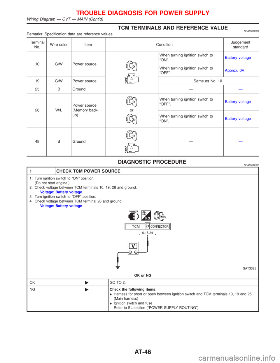
TCM TERMINALS AND REFERENCE VALUENCAT0031S01Remarks: Specification data are reference values.
Terminal
No.Wire color Item ConditionJudgement
standard
10 G/W Power source
When turning ignition switch to
ªONº.Battery voltage
When turning ignition switch to
ªOFFº.Approx. 0V
19 G/W Power source Same as No. 10
25 B Ground ÐÐ
28 W/LPower source
(Memory back-
up)
or
When turning ignition switch to
ªOFFº.Battery voltage
When turning ignition switch to
ªONº.Battery voltage
48 B Ground
ÐÐ
DIAGNOSTIC PROCEDURENCAT0031S03
1 CHECK TCM POWER SOURCE
1. Turn ignition switch to ªONº position.
(Do not start engine.)
2. Check voltage between TCM terminals 10, 19, 28 and ground.
Voltage: Battery voltage
3. Turn ignition switch to ªOFFº position.
4. Check voltage between TCM terminal 28 and ground.
Voltage: Battery voltage
SAT332J
OK or NG
OK©GO TO 2.
NG©Check the following items:
IHarness for short or open between ignition switch and TCM terminals 10, 19 and 25
(Main harness)
IIgnition switch and fuse
Refer to EL section (ªPOWER SUPPLY ROUTINGº).
TROUBLE DIAGNOSIS FOR POWER SUPPLY
Wiring Diagram Ð CVT Ð MAIN (Cont'd)
AT-46
Page 109 of 2267

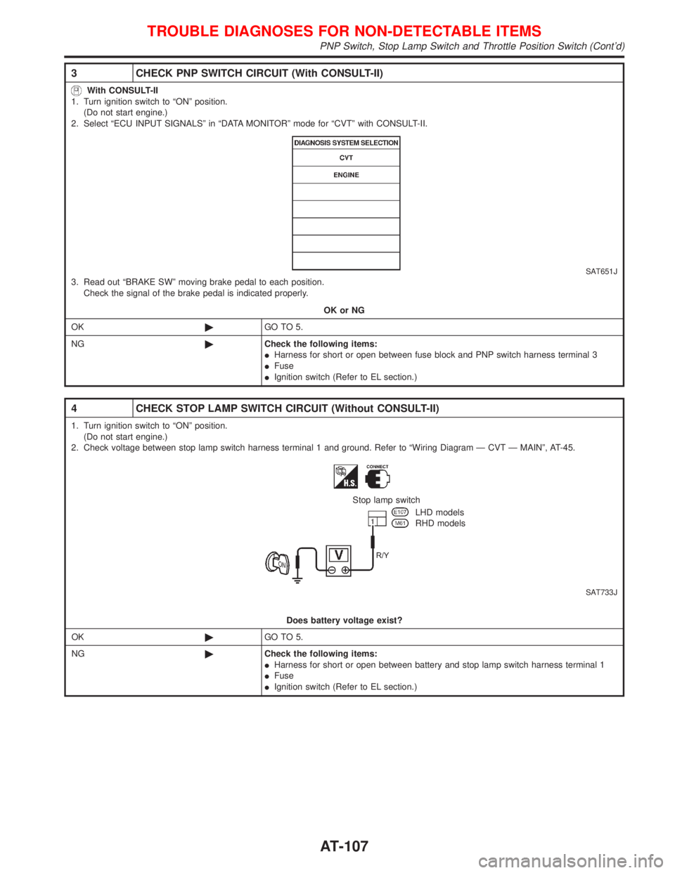
3 CHECK PNP SWITCH CIRCUIT (With CONSULT-II)
With CONSULT-II
1. Turn ignition switch to ªONº position.
(Do not start engine.)
2. Select ªECU INPUT SIGNALSº in ªDATA MONITORº mode for ªCVTº with CONSULT-II.
SAT651J3. Read out ªBRAKE SWº moving brake pedal to each position.
Check the signal of the brake pedal is indicated properly.
OK or NG
OK©GO TO 5.
NG©Check the following items:
IHarness for short or open between fuse block and PNP switch harness terminal 3
IFuse
IIgnition switch (Refer to EL section.)
4 CHECK STOP LAMP SWITCH CIRCUIT (Without CONSULT-II)
1. Turn ignition switch to ªONº position.
(Do not start engine.)
2. Check voltage between stop lamp switch harness terminal 1 and ground. Refer to ªWiring Diagram Ð CVT Ð MAINº, AT-45.
SAT733J
Stop lamp switch
LHD models
RHD models
Does battery voltage exist?
OK©GO TO 5.
NG©Check the following items:
IHarness for short or open between battery and stop lamp switch harness terminal 1
IFuse
IIgnition switch (Refer to EL section.)
TROUBLE DIAGNOSES FOR NON-DETECTABLE ITEMS
PNP Switch, Stop Lamp Switch and Throttle Position Switch (Cont'd)
AT-107
Page 112 of 2267
Wiring Diagram Ð AT Ð NONDTC
MODELS BEFORE VIN - P11U0548750NCAT0237
YAT155
BATTERYIGNITION SWITCH
ON or START
FUSE
BLOCK
(J/B)Refer to
EL-POWER.TCM
(TRANSMISSION
CONTROL MODULE)
Detectable line for DTC
Non-detectable line for DTC
Hyper CVT models
Hyper CVT M6 models
SPORT indicator lamp
CVT warning lamp
UNIFIED METER CONTROL UNITCOMBINATION
METER
INDICATOR
CONTROL
UNIT
REFER TO THE FOLLOWING
FUSE BLOCK - Junction Box (J/B)
TROUBLE DIAGNOSES FOR NON-DETECTABLE ITEMS
Wiring Diagram Ð AT Ð NONDTC
AT-110
Page 184 of 2267
Wiring Diagram Ð ABS Ð
MODELS WITH SELF-DIAGNOSIS FUNCTION
YBR208 BATTERYIGNITION SWITCH
ON or START
FUSE
BLOCK
(J/B)Refer to EL-POWER.
: LHD models
: RHD models: CVT models
: M/T models
RELEASEDDEPRESSEDSTOP LAMP
SWITCH
FUSE
BLOCK
(J/B)COMBINATION METER
(ABS WARNING LAMP)
ABS ACTUATOR
AND ELECTRIC
UNIT
(CONTROL UNIT)
TCM
(TRANSMISSION CON-
TROL MODULE)DATA LINK CON-
NECTOR
Refer to las page (Foldout page).
TROUBLE DIAGNOSES
BR-62
Page 545 of 2267
Main Power Supply and Ground Circuit
WIRING DIAGRAMNCEC0047
YEC770
BATTERY
Refer to EL-POWER.
OFF
ACCST
ONIGNITION
SWITCH
FUSE
BLOCK
(J/B)
To EC-IGN/SG,
EC-TP/SW,
EC-AAC/V,
EC-EGR,
EC-EGVC/V ECM RELAY
: Detectable line for DTC
: Non-detectable line for DTC
Refer to last page (Foldout page) ECM
TROUBLE DIAGNOSIS FOR POWER SUPPLYQG16I18DE
Main Power Supply and Ground Circuit
EC-103
Page 547 of 2267
2 CHECK POWER SUPPLY-I
1. Turn ignition switch ªOFFº and then ªONº.
2. Check voltage between ECM terminal 43 and ground with CONSULT-II or tester.
SEF981WVoltage: Battery voltage
OK or NG
OK©GO TO 9.
NG©GO TO 3.
3 DETECT MALFUNCTIONING PART
Check the following.
I10A Fuse
I40A fusible link
IHarness connectors M50, F104
IHarness for open or short between ECM and fuse block
IHarness for open or short between fuse block and ignition switch
©Repair harness or connectors.
4 CHECK ECM GROUND CIRCUIT FOR OPEN AND SHORT-I
1. Turn ignition switch ªOFFº.
2. Disconnect ECM harness connector.
3. Check harness continuity between ECM terminals 48, 57, 106, 108 and engine ground.
Refer to WIRING DIAGRAM.
Continuity should exist.
4. Also check harness for short to power.
OK or NG
OK©GO TO 5.
NG©Repair open circuit or short to power in harness or connectors.
TROUBLE DIAGNOSIS FOR POWER SUPPLYQG16I18DE
Main Power Supply and Ground Circuit (Cont'd)
EC-105
Page 550 of 2267
12 CHECK HARNESS CONTINUITY BETWEEN ECM RELAY AND ECM
1. Disconnect ECM harness connector.
2. Disconnect ECM relay.
SEF984W3. Check harness continuity between ECM terminals 110, 112 and relay terminal 5.
Refer to wiring diagram.
Continuity should exist.
4. Also check harness for short to ground and short to power.
OK or NG
OK©GO TO 14.
NG©GO TO 13.
13 DETECT MALFUNCTIONING PART
Check the following.
IHarness connectors E90, F73
IHarness for open or short between ECM relay and ECM
©Repair open circuit or short to ground or short to power in harness or connectors.
14 CHECK VOLTAGE BETWEEN ECM RELAY AND GROUND
Check voltage between relay terminals 1, 3 and ground with CONSULT-II or tester.
SEF985WVoltage: Battery voltage
OK or NG
OK©GO TO 16.
NG©GO TO 15.
15 DETECT MALFUNCTIONING PART
Check the harness for open or short between ECM relay and fuse.
©Repair harness or connectors.
TROUBLE DIAGNOSIS FOR POWER SUPPLYQG16I18DE
Main Power Supply and Ground Circuit (Cont'd)
EC-108