Page 133 of 2267
Dual Proportioning Valve
INSPECTION
CAUTION:
lCarefully monitor brake fluid level at master cylinder.
lUse new brake fluid ªDOT 4º.
lBe careful not to splash brake fluid on painted areas; it
may cause paint damage. If brake fluid is splashed on
paint areas, wash it away with water immediately.
lDepress pedal slowly when raising front brake pressure.
lCheck rear brake pressure at least 2 seconds after front
brake pressure reaches specified value.
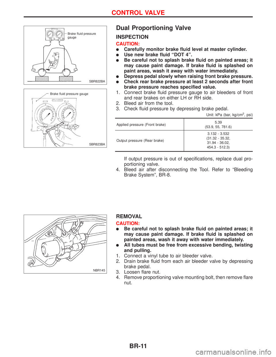
1. Connect brake fluid pressure gauge to air bleeders of front
and rear brakes on either LH or RH side.
2. Bleed air from the tool.
3. Check fluid pressure by depressing brake pedal.
Unit: kPa (bar, kg/cm2, psi)
Applied pressure (Front brake)5.39
(53.9, 55, 781.6)
Output pressure (Rear brake)3.132 - 3.532
(31.32 - 35.32,
31.94 - 36.02,
454.3 - 512.3)
If output pressure is out of specifications, replace dual pro-
portioning valve.
4. Bleed air after disconnecting the Tool. Refer to ªBleeding
Brake Systemº, BR-8.
REMOVAL
CAUTION:
lBe careful not to splash brake fluid on painted areas; it
may cause paint damage. If brake fluid is splashed on
painted areas, wash it away with water immediately.
lAll tubes must be free from excessive bending, twisting
and pulling.
1. Connect a vinyl tube to air bleeder valve.
2. Drain brake fluid from each air bleeder valve by depressing
brake pedal.
3. Loosen flare nut.
4. Remove proportioning valve mounting bolt, then remove flare
nut.
SBR822BA Brake fluid pressure
gauge
SBR823BA Brake fluid pressure gauge
NBR145
CONTROL VALVE
BR-11
Page 148 of 2267
Pad Replacement
WARNING:
Clean brake pads with a vacuum dust collector to minimize
the hazard of airborne particles or other materials.
CAUTION:
lWhen cylinder body is open, do not depress brake pedal
because piston will pop out.
lBe careful not to damage piston boot or get oil on rotor.
Always replace shims when replacing pads.
lIf shims are rusted or show peeling of the rubber coat,
replace them with new shims.
lIt is not necessary to remove connecting bolt except for
disassembly or replacement of caliper assembly. In this
case, suspend cylinder body with wire so as not to
stretch brake hose.
lBurnish the brake contact surfaces after refinishing or
replacing rotors, after replacing pads, or if a soft pedal
occurs at very low mileage.
Refer to ªBrake Burnishing Procedureº, ªCHECK AND
ADJUSTMENTº, BR-7.
NBR439
FRONT DISC BRAKESR20DE - M/T
BR-26
Page 149 of 2267
REMOVAL
1. Remove the housing retaining spring.
2. Wipe away any dirt from the guide pins between the torque
member and the cylinder body.
3. Pull out the protective caps from the guide sleeves.
4. Usea7-mmALLEN key to unscrew the guide pins
from the torque member.
5. Partially remove the guide pins from the guide sleeve.
6. Pull the cylinder body manually towards the outer side of the
vehicle so that the piston is slightly pressed back.
7. Remove the cylinder body and hang it on a wire in the wheel
arch in a suitable position.
Make sure there is no strain on the brake hose piping.
8. Remove the brake pad on the piston side from the piston.
9. Remove the second brake pad from the torque member.
NBR292 Spring Cylinder bodyTorque member lug.Torque member lug Locating
holes
NBR300 Protective
caps
NBR290
Wire
Spring
FRONT DISC BRAKESR20DE - M/T
Pad Replacement (Cont'd)
BR-27
Page 150 of 2267
CAUTION:
Do not use any sharp tools or cleaning agents which con-
tains mineral oil. Damage to the installation can occur.
10. Clean the cylinder body and guide grooves in the torque
member.
11. Check the dust cover and guide sleeves for damage.
12. Measure the amount of wear on the brake pad
Standard pad thickness:
11 mm (0.43 in)
Pad wear limit:
2.0 mm (0.079 in)
14. Press the piston fully back with a suitable tool.
CAUTION:
Carefully monitor brake fluid level to avoid brake fluid from
returning to the reservoir when pushing back the piston.
Installation
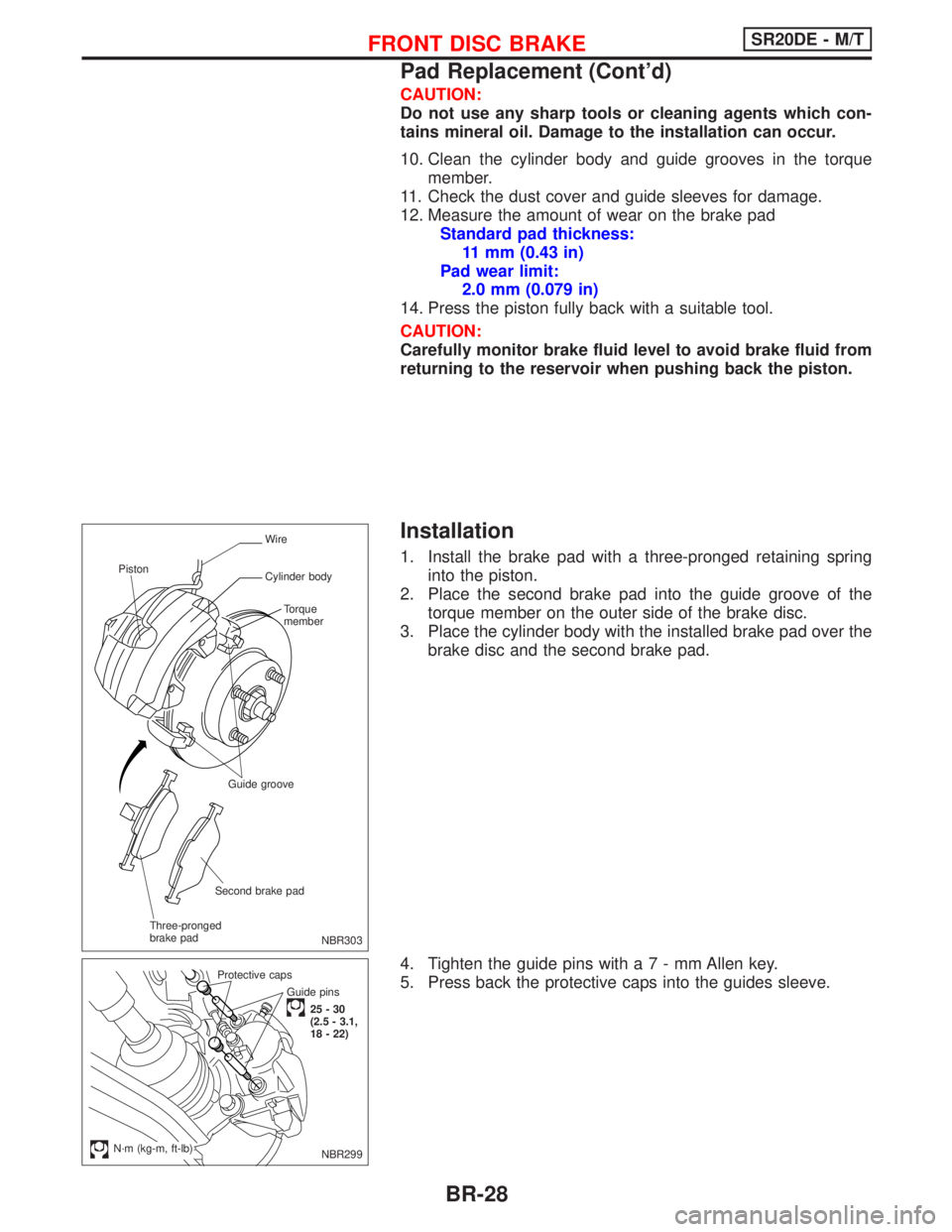
1. Install the brake pad with a three-pronged retaining spring
into the piston.
2. Place the second brake pad into the guide groove of the
torque member on the outer side of the brake disc.
3. Place the cylinder body with the installed brake pad over the
brake disc and the second brake pad.
4. Tighten the guide pins witha7-mmAllen key.
5. Press back the protective caps into the guides sleeve.
NBR303
Wire
Cylinder body
Torque
member
Guide groove
Second brake pad
Three-pronged
brake pad Piston
Guide pins
25-30
(2.5 - 3.1,
18 - 22) Protective caps
.N´m (kg-m, ft-lb)NBR299
FRONT DISC BRAKESR20DE - M/T
Pad Replacement (Cont'd)
BR-28
Page 151 of 2267
6. Check the cylinder body retaining spring for damage if the
spring is defective, replace the spring.
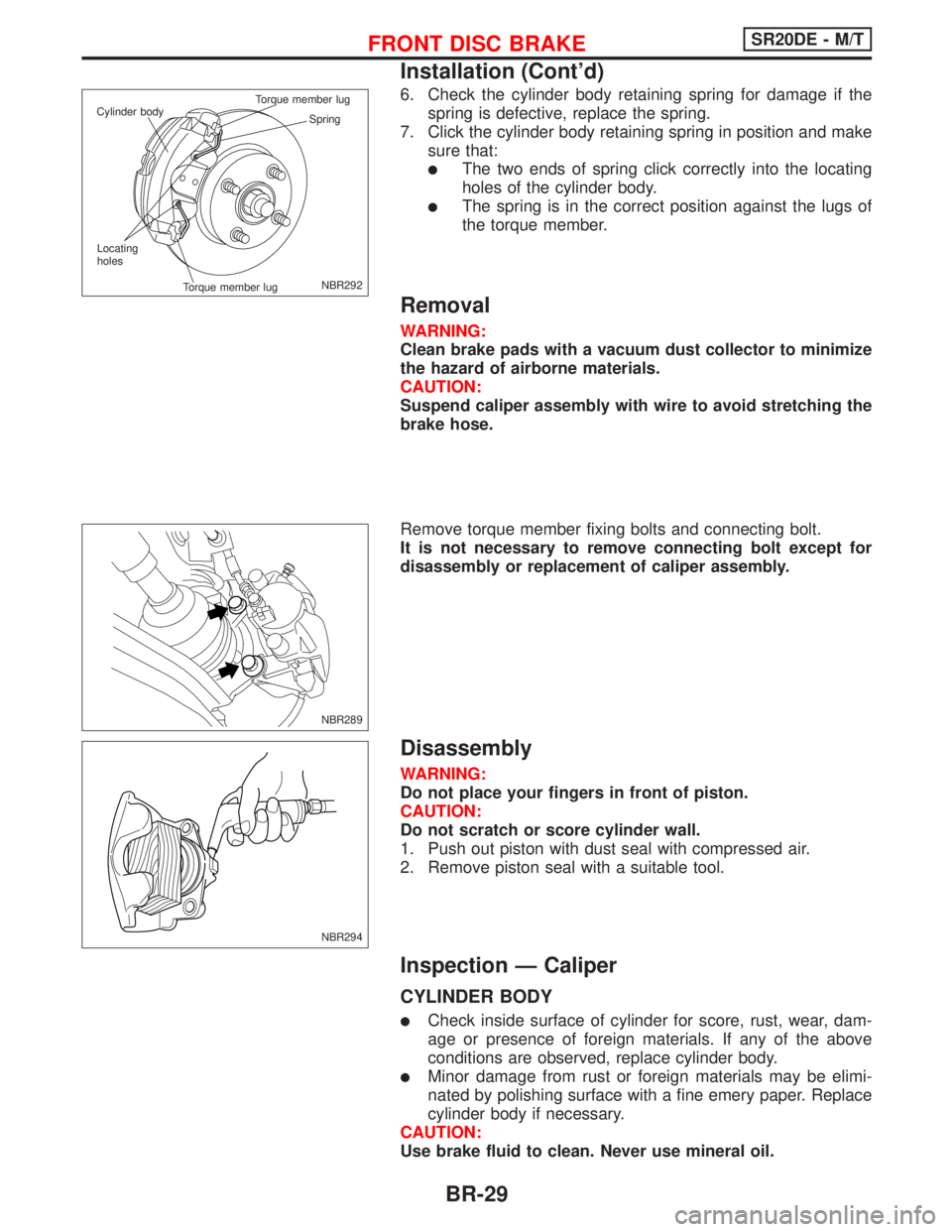
7. Click the cylinder body retaining spring in position and make
sure that:
lThe two ends of spring click correctly into the locating
holes of the cylinder body.
lThe spring is in the correct position against the lugs of
the torque member.
Removal
WARNING:
Clean brake pads with a vacuum dust collector to minimize
the hazard of airborne materials.
CAUTION:
Suspend caliper assembly with wire to avoid stretching the
brake hose.
Remove torque member fixing bolts and connecting bolt.
It is not necessary to remove connecting bolt except for
disassembly or replacement of caliper assembly.
Disassembly
WARNING:
Do not place your fingers in front of piston.
CAUTION:
Do not scratch or score cylinder wall.
1. Push out piston with dust seal with compressed air.
2. Remove piston seal with a suitable tool.
Inspection Ð Caliper
CYLINDER BODY
lCheck inside surface of cylinder for score, rust, wear, dam-
age or presence of foreign materials. If any of the above
conditions are observed, replace cylinder body.
lMinor damage from rust or foreign materials may be elimi-
nated by polishing surface with a fine emery paper. Replace
cylinder body if necessary.
CAUTION:
Use brake fluid to clean. Never use mineral oil.
NBR292 Spring Cylinder bodyTorque member lug
Torque member lug Locating
holes
NBR289
NBR294
FRONT DISC BRAKESR20DE - M/T
Installation (Cont'd)
BR-29
Page 152 of 2267
PISTON
CAUTION:
Piston sliding surface is plated. Do not polish with emery
paper even if rust or foreign materials are stuck to sliding
surface.
Check piston for score, rust, wear, damage or presence of for-
eign materials. Replace if any of the above conditions are
observed.
GUIDE PIN, BOLT, AND RETAINING SPRING
Check for wear, cracks or other damage. Replace if any of the
above conditions are observed.
FRONT DISC BRAKESR20DE - M/T
Inspection Ð Caliper (Cont'd)
BR-30
Page 171 of 2267
Inspection
1. Check control lever for wear or other damage. Replace if
necessary.
2. Check wires for discontinuity or deterioration. Replace if nec-
essary.
3. Check warning lamp and switch. Replace if necessary.
4. Check parts at each connecting portion and, if found
deformed or damaged, replace the parts.
Adjustment
Before or after adjustment, pay attention to the following points.
lMake sure the toggle lever of the rear disc brakes returns to
stopper, when the parking lever is released.
lThere is no drag when parking brake lever is released.
lVehicle is unladen.
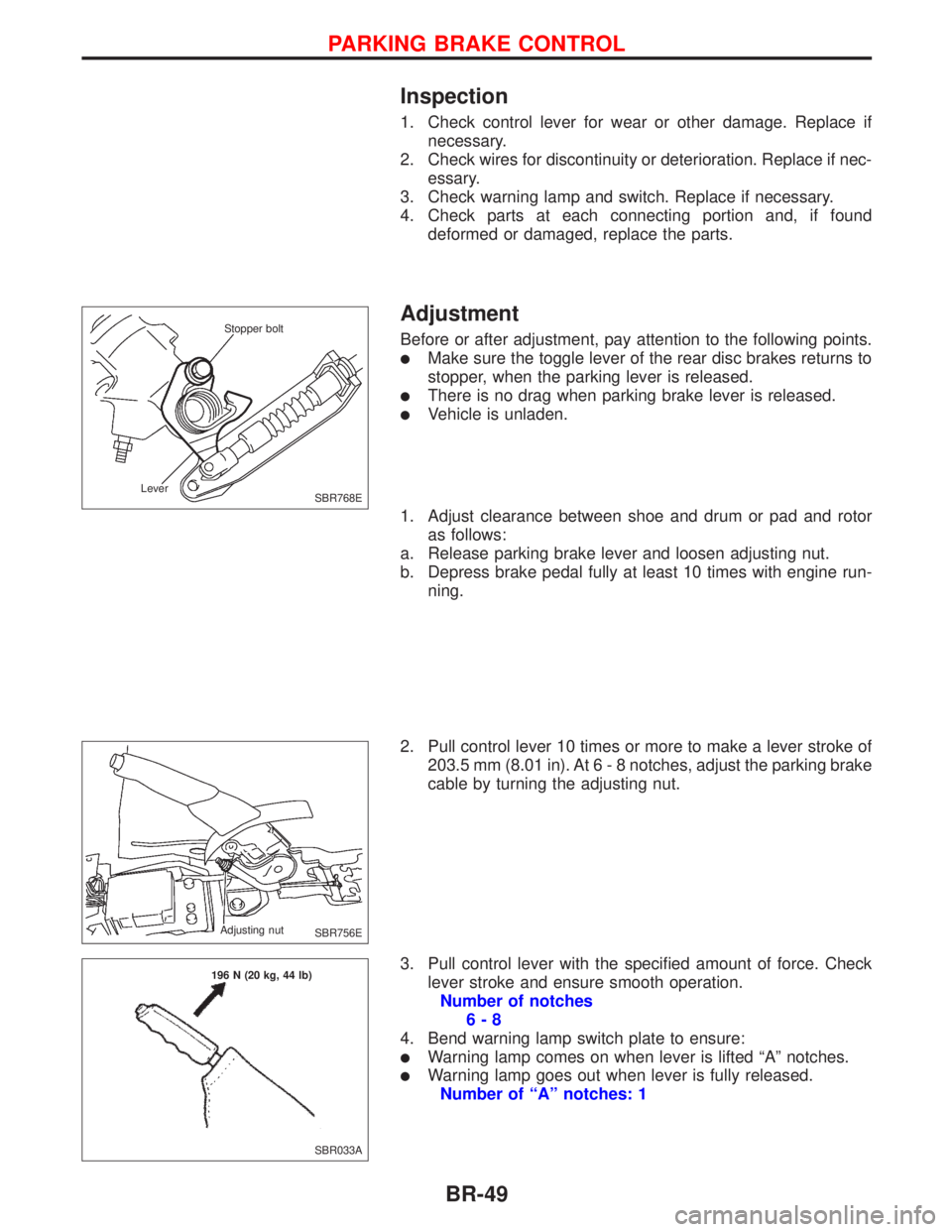
1. Adjust clearance between shoe and drum or pad and rotor
as follows:
a. Release parking brake lever and loosen adjusting nut.
b. Depress brake pedal fully at least 10 times with engine run-
ning.
2. Pull control lever 10 times or more to make a lever stroke of
203.5 mm (8.01 in). At6-8notches, adjust the parking brake
cable by turning the adjusting nut.
3. Pull control lever with the specified amount of force. Check
lever stroke and ensure smooth operation.
Number of notches
6-8
4. Bend warning lamp switch plate to ensure:
lWarning lamp comes on when lever is lifted ªAº notches.
lWarning lamp goes out when lever is fully released.
Number of ªAº notches: 1
SBR768E Stopper bolt
Lever
SBR756E Adjusting nut
SBR033A 196 N (20 kg, 44 lb)
PARKING BRAKE CONTROL
BR-49
Page 1745 of 2267
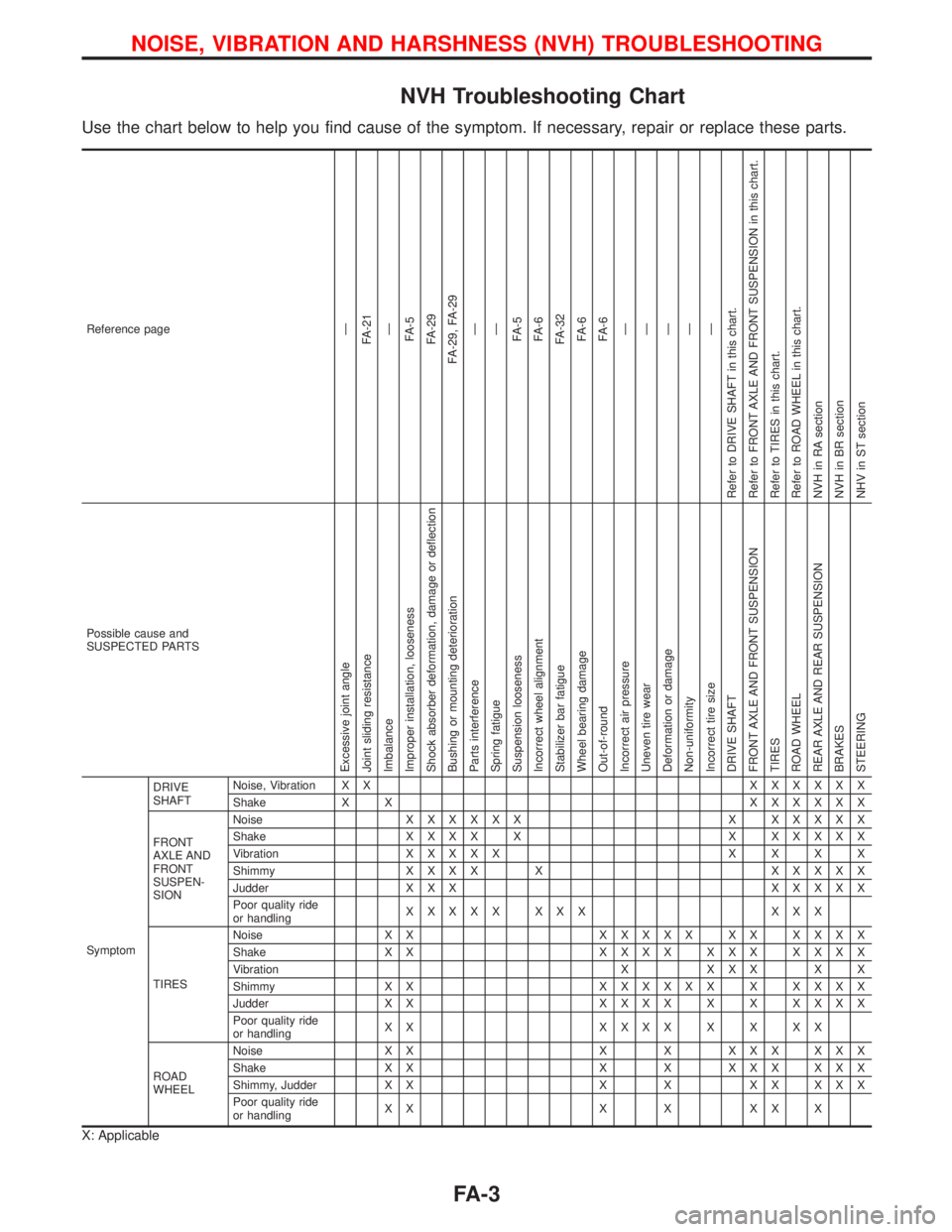
NVH Troubleshooting Chart
Use the chart below to help you find cause of the symptom. If necessary, repair or replace these parts.
Reference pageÐ
FA-21
Ð
FA-5
FA-29
FA-29, FA-29
Ð
Ð
FA-5
FA-6
FA-32
FA-6
FA-6
Ð
Ð
Ð
Ð
Ð
Refer to DRIVE SHAFT in this chart.
Refer to FRONT AXLE AND FRONT SUSPENSION in this chart.
Refer to TIRES in this chart.
Refer to ROAD WHEEL in this chart.
NVH in RA section
NVH in BR section
NHV in ST section
Possible cause and
SUSPECTED PARTS
Excessive joint angle
Joint sliding resistance
Imbalance
Improper installation, looseness
Shock absorber deformation, damage or deflection
Bushing or mounting deterioration
Parts interference
Spring fatigue
Suspension looseness
Incorrect wheel alignment
Stabilizer bar fatigue
Wheel bearing damage
Out-of-round
Incorrect air pressure
Uneven tire wear
Deformation or damage
Non-uniformity
Incorrect tire size
DRIVE SHAFT
FRONT AXLE AND FRONT SUSPENSION
TIRES
ROAD WHEEL
REAR AXLE AND REAR SUSPENSION
BRAKES
STEERING
SymptomDRIVE
SHAFTNoise, Vibration X XXXXXXX
Shake X XXXXXXX
FRONT
AXLE AND
FRONT
SUSPEN-
SIONNoiseXXXXXX X XXXXX
ShakeXXXX X X XXXXX
VibrationXXXXXXXXX
ShimmyXXXX X XXXXX
Judder X X XXXXXX
Poor quality ride
or handlingXXXXX XXX XXX
TIRESNoise X XXXXXX XX XXXX
Shake X XXXXX XXX XXXX
Vibration X X X X X X
Shimmy X XXXXXXX X XXXX
Judder X XXXXX X X XXXX
Poor quality ride
or handlingXX XXXXXXXX
ROAD
WHEELNoise X X X X X X X X X X
Shake X X X X X X X X X X
Shimmy, Judder X X X X X X X X X
Poor quality ride
or handlingXX X X XX X
X: Applicable
NOISE, VIBRATION AND HARSHNESS (NVH) TROUBLESHOOTING
FA-3