1999 NISSAN PRIMERA audio
[x] Cancel search: audioPage 126 of 2267
Precautions When Working On ABS
lUse recommended tyres in combination with ABS.
lInstall tyres or studded tyres, etc. with the same size.
lIf different sizes of tyres, or tyres other than the ones
recommended for use with the ABS, are fitted, stopping
distance will increase and control and stability could
deteriorate.
lWhen changing brake pads, use Nissan genuine parts.
lWhen fitting radios etc, do not position the radio unit,
antenna, or antenna cables within an area of about 100
mm (3.94 in) of the control unit.
lWhen doing any work that requires electro-welding, first
remove the control unit.
lMake sure when taking a power supply for the audio,
lamps etc., not to take this from any ABS-related har-
ness. (Refer to the electrical wiring diagrams for ABS-
related harnesses)
Wiring Diagrams and Trouble Diagnosis
When you read wiring diagrams, refer to the following:
lGI-11, ªHOW TO READ WIRING DIAGRAMSº
lEL-10, ªPOWER SUPPLY ROUTINGº
When you perform trouble diagnosis, refer to the following:
lGI-35, ªHOW TO FOLLOW TEST GROUPS IN TROUBLE DIAGNOSISº
lGI-24, ªHOW TO PERFORM EFFICIENT DIAGNOSES FOR AN ELECTRICAL INCIDENTº
PRECAUTIONS
BR-4
Page 229 of 2267
CAUTION:
lDisconnect both battery cables in advance.
lDisconnect air bag system line in advance.
lNever tamper with or force air bag lid open, as this may adversely affect air bag performance.
lBe careful not to scratch pad and other parts.
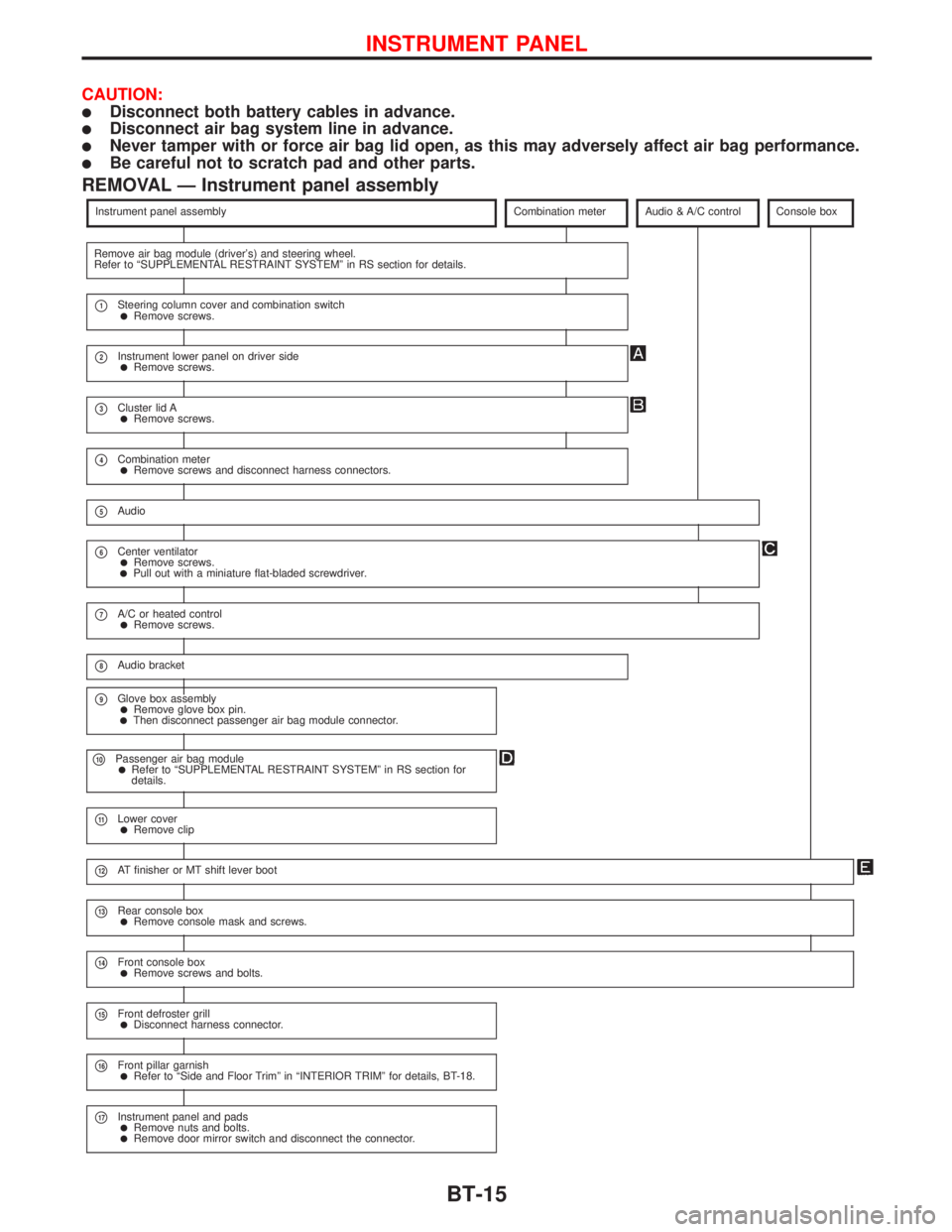
REMOVAL Ð Instrument panel assembly
Instrument panel assemblyCombination meterAudio & A/C controlConsole box
Remove air bag module (driver's) and steering wheel.
Refer to ªSUPPLEMENTAL RESTRAINT SYSTEMº in RS section for details.
p1Steering column cover and combination switchlRemove screws.
p2Instrument lower panel on driver sidelRemove screws.
p3Cluster lid AlRemove screws.
p4Combination meterlRemove screws and disconnect harness connectors.
p5Audio
p6Center ventilatorlRemove screws.lPull out with a miniature flat-bladed screwdriver.
p7A/C or heated controllRemove screws.
p8Audio bracket
p9Glove box assemblylRemove glove box pin.lThen disconnect passenger air bag module connector.
p10Passenger air bag modulelRefer to ªSUPPLEMENTAL RESTRAINT SYSTEMº in RS section for
details.
p11Lower coverlRemove clip
p12AT finisher or MT shift lever boot
p13Rear console boxlRemove console mask and screws.
p14Front console boxlRemove screws and bolts.
p15Front defroster grilllDisconnect harness connector.
p16Front pillar garnishlRefer to ªSide and Floor Trimº in ªINTERIOR TRIMº for details, BT-18.
p17Instrument panel and padslRemove nuts and bolts.lRemove door mirror switch and disconnect the connector.
INSTRUMENT PANEL
BT-15
Page 713 of 2267
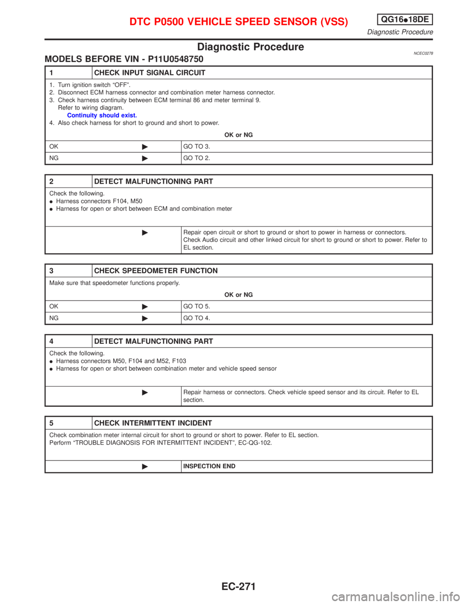
Diagnostic ProcedureNCEC0278MODELS BEFORE VIN - P11U0548750
1 CHECK INPUT SIGNAL CIRCUIT
1. Turn ignition switch ªOFFº.
2. Disconnect ECM harness connector and combination meter harness connector.
3. Check harness continuity between ECM terminal 86 and meter terminal 9.
Refer to wiring diagram.
Continuity should exist.
4. Also check harness for short to ground and short to power.
OK or NG
OK©GO TO 3.
NG©GO TO 2.
2 DETECT MALFUNCTIONING PART
Check the following.
IHarness connectors F104, M50
IHarness for open or short between ECM and combination meter
©Repair open circuit or short to ground or short to power in harness or connectors.
Check Audio circuit and other linked circuit for short to ground or short to power. Refer to
EL section.
3 CHECK SPEEDOMETER FUNCTION
Make sure that speedometer functions properly.
OK or NG
OK©GO TO 5.
NG©GO TO 4.
4 DETECT MALFUNCTIONING PART
Check the following.
IHarness connectors M50, F104 and M52, F103
IHarness for open or short between combination meter and vehicle speed sensor
©Repair harness or connectors. Check vehicle speed sensor and its circuit. Refer to EL
section.
5 CHECK INTERMITTENT INCIDENT
Check combination meter internal circuit for short to ground or short to power. Refer to EL section.
Perform ªTROUBLE DIAGNOSIS FOR INTERMITTENT INCIDENTº, EC-QG-102.
©INSPECTION END
DTC P0500 VEHICLE SPEED SENSOR (VSS)QG16I18DE
Diagnostic Procedure
EC-271
Page 714 of 2267
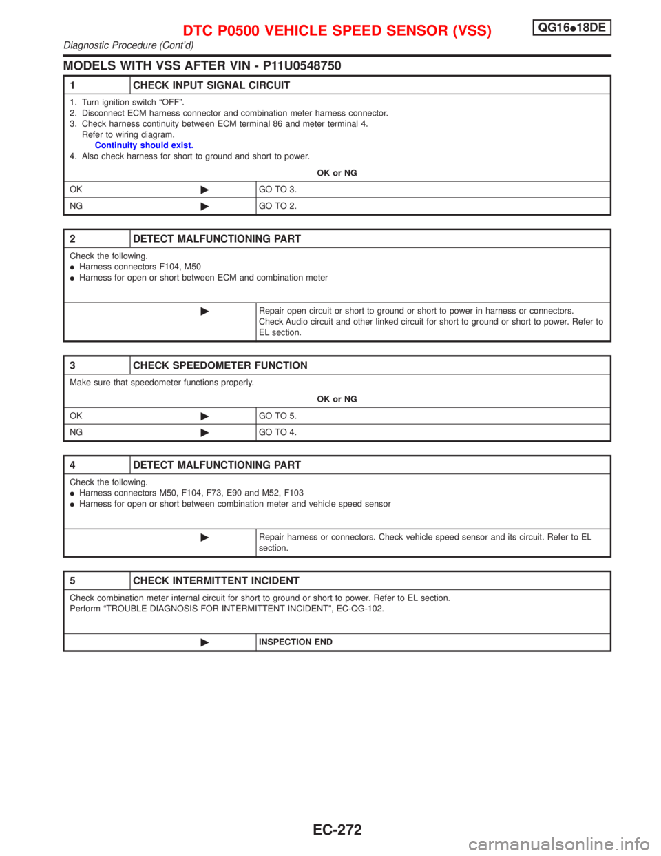
MODELS WITH VSS AFTER VIN - P11U0548750
1 CHECK INPUT SIGNAL CIRCUIT
1. Turn ignition switch ªOFFº.
2. Disconnect ECM harness connector and combination meter harness connector.
3. Check harness continuity between ECM terminal 86 and meter terminal 4.
Refer to wiring diagram.
Continuity should exist.
4. Also check harness for short to ground and short to power.
OK or NG
OK©GO TO 3.
NG©GO TO 2.
2 DETECT MALFUNCTIONING PART
Check the following.
IHarness connectors F104, M50
IHarness for open or short between ECM and combination meter
©Repair open circuit or short to ground or short to power in harness or connectors.
Check Audio circuit and other linked circuit for short to ground or short to power. Refer to
EL section.
3 CHECK SPEEDOMETER FUNCTION
Make sure that speedometer functions properly.
OK or NG
OK©GO TO 5.
NG©GO TO 4.
4 DETECT MALFUNCTIONING PART
Check the following.
IHarness connectors M50, F104, F73, E90 and M52, F103
IHarness for open or short between combination meter and vehicle speed sensor
©Repair harness or connectors. Check vehicle speed sensor and its circuit. Refer to EL
section.
5 CHECK INTERMITTENT INCIDENT
Check combination meter internal circuit for short to ground or short to power. Refer to EL section.
Perform ªTROUBLE DIAGNOSIS FOR INTERMITTENT INCIDENTº, EC-QG-102.
©INSPECTION END
DTC P0500 VEHICLE SPEED SENSOR (VSS)QG16I18DE
Diagnostic Procedure (Cont'd)
EC-272
Page 715 of 2267
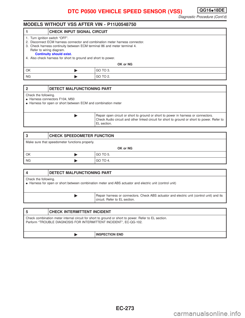
MODELS WITHOUT VSS AFTER VIN - P11U0548750
1 CHECK INPUT SIGNAL CIRCUIT
1. Turn ignition switch ªOFFº.
2. Disconnect ECM harness connector and combination meter harness connector.
3. Check harness continuity between ECM terminal 86 and meter terminal 4.
Refer to wiring diagram.
Continuity should exist.
4. Also check harness for short to ground and short to power.
OK or NG
OK©GO TO 3.
NG©GO TO 2.
2 DETECT MALFUNCTIONING PART
Check the following.
IHarness connectors F104, M50
IHarness for open or short between ECM and combination meter
©Repair open circuit or short to ground or short to power in harness or connectors.
Check Audio circuit and other linked circuit for short to ground or short to power. Refer to
EL section.
3 CHECK SPEEDOMETER FUNCTION
Make sure that speedometer functions properly.
OK or NG
OK©GO TO 5.
NG©GO TO 4.
4 DETECT MALFUNCTIONING PART
Check the following.
IHarness for open or short between combination meter and ABS actuator and electric unit (control unit)
©Repair harness or connectors. Check ABS actuator and electric unit (control unit) and its
circuit. Refer to EL section.
5 CHECK INTERMITTENT INCIDENT
Check combination meter internal circuit for short to ground or short to power. Refer to EL section.
Perform ªTROUBLE DIAGNOSIS FOR INTERMITTENT INCIDENTº, EC-QG-102.
©INSPECTION END
DTC P0500 VEHICLE SPEED SENSOR (VSS)QG16I18DE
Diagnostic Procedure (Cont'd)
EC-273
Page 1060 of 2267
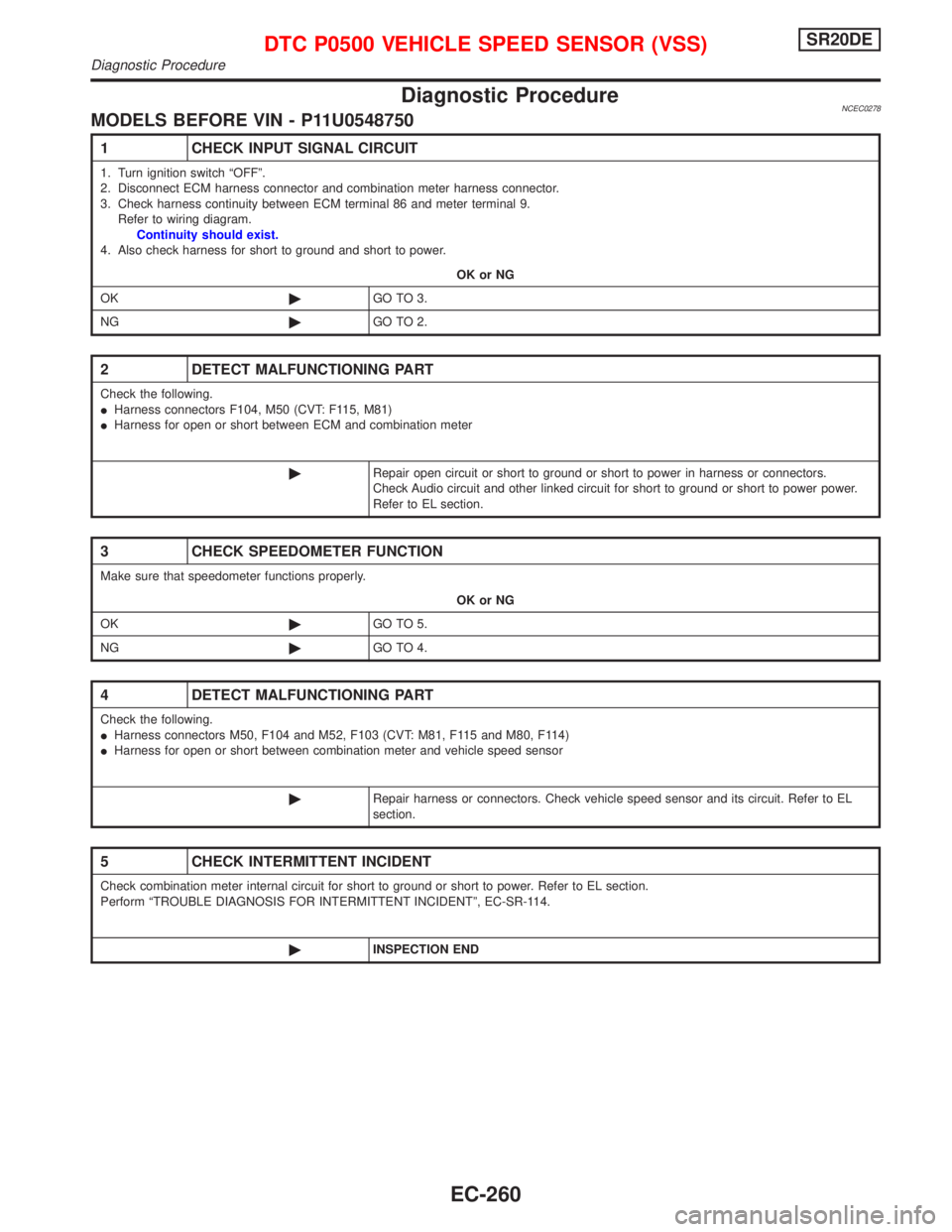
Diagnostic ProcedureNCEC0278MODELS BEFORE VIN - P11U0548750
1 CHECK INPUT SIGNAL CIRCUIT
1. Turn ignition switch ªOFFº.
2. Disconnect ECM harness connector and combination meter harness connector.
3. Check harness continuity between ECM terminal 86 and meter terminal 9.
Refer to wiring diagram.
Continuity should exist.
4. Also check harness for short to ground and short to power.
OK or NG
OK©GO TO 3.
NG©GO TO 2.
2 DETECT MALFUNCTIONING PART
Check the following.
IHarness connectors F104, M50 (CVT: F115, M81)
IHarness for open or short between ECM and combination meter
©Repair open circuit or short to ground or short to power in harness or connectors.
Check Audio circuit and other linked circuit for short to ground or short to power power.
Refer to EL section.
3 CHECK SPEEDOMETER FUNCTION
Make sure that speedometer functions properly.
OK or NG
OK©GO TO 5.
NG©GO TO 4.
4 DETECT MALFUNCTIONING PART
Check the following.
IHarness connectors M50, F104 and M52, F103 (CVT: M81, F115 and M80, F114)
IHarness for open or short between combination meter and vehicle speed sensor
©Repair harness or connectors. Check vehicle speed sensor and its circuit. Refer to EL
section.
5 CHECK INTERMITTENT INCIDENT
Check combination meter internal circuit for short to ground or short to power. Refer to EL section.
Perform ªTROUBLE DIAGNOSIS FOR INTERMITTENT INCIDENTº, EC-SR-114.
©INSPECTION END
DTC P0500 VEHICLE SPEED SENSOR (VSS)SR20DE
Diagnostic Procedure
EC-260
Page 1061 of 2267
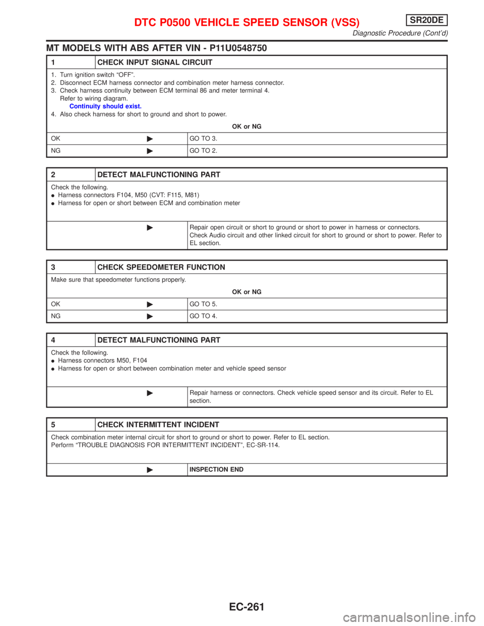
MT MODELS WITH ABS AFTER VIN - P11U0548750
1 CHECK INPUT SIGNAL CIRCUIT
1. Turn ignition switch ªOFFº.
2. Disconnect ECM harness connector and combination meter harness connector.
3. Check harness continuity between ECM terminal 86 and meter terminal 4.
Refer to wiring diagram.
Continuity should exist.
4. Also check harness for short to ground and short to power.
OK or NG
OK©GO TO 3.
NG©GO TO 2.
2 DETECT MALFUNCTIONING PART
Check the following.
IHarness connectors F104, M50 (CVT: F115, M81)
IHarness for open or short between ECM and combination meter
©Repair open circuit or short to ground or short to power in harness or connectors.
Check Audio circuit and other linked circuit for short to ground or short to power. Refer to
EL section.
3 CHECK SPEEDOMETER FUNCTION
Make sure that speedometer functions properly.
OK or NG
OK©GO TO 5.
NG©GO TO 4.
4 DETECT MALFUNCTIONING PART
Check the following.
IHarness connectors M50, F104
IHarness for open or short between combination meter and vehicle speed sensor
©Repair harness or connectors. Check vehicle speed sensor and its circuit. Refer to EL
section.
5 CHECK INTERMITTENT INCIDENT
Check combination meter internal circuit for short to ground or short to power. Refer to EL section.
Perform ªTROUBLE DIAGNOSIS FOR INTERMITTENT INCIDENTº, EC-SR-114.
©INSPECTION END
DTC P0500 VEHICLE SPEED SENSOR (VSS)SR20DE
Diagnostic Procedure (Cont'd)
EC-261
Page 1062 of 2267
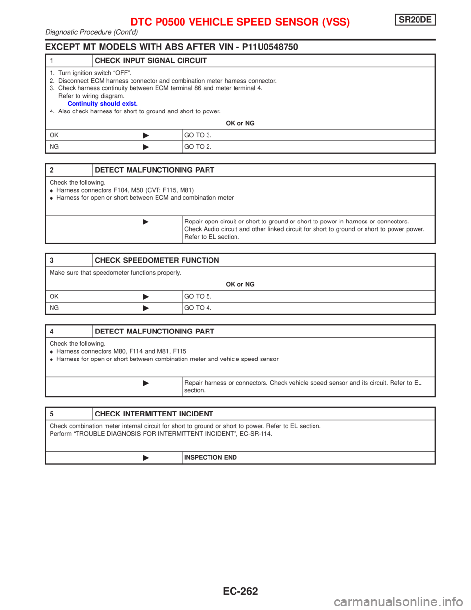
EXCEPT MT MODELS WITH ABS AFTER VIN - P11U0548750
1 CHECK INPUT SIGNAL CIRCUIT
1. Turn ignition switch ªOFFº.
2. Disconnect ECM harness connector and combination meter harness connector.
3. Check harness continuity between ECM terminal 86 and meter terminal 4.
Refer to wiring diagram.
Continuity should exist.
4. Also check harness for short to ground and short to power.
OK or NG
OK©GO TO 3.
NG©GO TO 2.
2 DETECT MALFUNCTIONING PART
Check the following.
IHarness connectors F104, M50 (CVT: F115, M81)
IHarness for open or short between ECM and combination meter
©Repair open circuit or short to ground or short to power in harness or connectors.
Check Audio circuit and other linked circuit for short to ground or short to power power.
Refer to EL section.
3 CHECK SPEEDOMETER FUNCTION
Make sure that speedometer functions properly.
OK or NG
OK©GO TO 5.
NG©GO TO 4.
4 DETECT MALFUNCTIONING PART
Check the following.
IHarness connectors M80, F114 and M81, F115
IHarness for open or short between combination meter and vehicle speed sensor
©Repair harness or connectors. Check vehicle speed sensor and its circuit. Refer to EL
section.
5 CHECK INTERMITTENT INCIDENT
Check combination meter internal circuit for short to ground or short to power. Refer to EL section.
Perform ªTROUBLE DIAGNOSIS FOR INTERMITTENT INCIDENTº, EC-SR-114.
©INSPECTION END
DTC P0500 VEHICLE SPEED SENSOR (VSS)SR20DE
Diagnostic Procedure (Cont'd)
EC-262