Page 36 of 2267
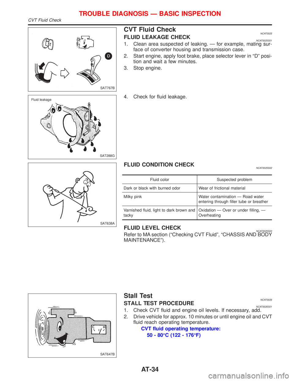
CVT Fluid CheckNCAT0025FLUID LEAKAGE CHECKNCAT0025S011. Clean area suspected of leaking. Ð for example, mating sur-
face of converter housing and transmission case.
2. Start engine, apply foot brake, place selector lever in ªDº posi-
tion and wait a few minutes.
3. Stop engine.
4. Check for fluid leakage.
FLUID CONDITION CHECKNCAT0025S02
Fluid color Suspected problem
Dark or black with burned odor Wear of frictional material
Milky pink Water contamination Ð Road water
entering through filler tube or breather
Varnished fluid, light to dark brown and
tackyOxidation Ð Over or under filling, Ð
Overheating
FLUID LEVEL CHECKNCAT0025S03Refer to MA section (ªChecking CVT Fluidº, ªCHASSIS AND BODY
MAINTENANCEº).
Stall TestNCAT0026STALL TEST PROCEDURENCAT0026S011. Check CVT fluid and engine oil levels. If necessary, add.
2. Drive vehicle for approx. 10 minutes or until engine oil and CVT
fluid reach operating temperature.
CVT fluid operating temperature:
50 - 80ÉC (122 - 176ÉF)
SAT767B
SAT288G Fluid leakage
SAT638A
SAT647B
TROUBLE DIAGNOSIS Ð BASIC INSPECTION
CVT Fluid Check
AT-34
Page 822 of 2267
System ChartNCEC0013
Input (Sensor) ECM Function Output (Actuator)
ICamshaft position sensor
IMass air flow sensor
IEngine coolant temperature sensor
IHeated oxygen sensor 1 (front)
IIgnition switch
IThrottle position sensor
IPNP switch
IAir conditioner switch
IKnock sensor
ICrankshaft position sensor (OBD)*1
IBattery voltage
IPower steering oil pressure switch
IVehicle speed sensor or ABS actuator and
electric unit (control unit)
IIntake air temperature sensor
IHeated oxygen sensor 2 (rear)*2
ITCM (Transmission control module)*3
IClosed throttle position switch
IElectrical load
IRefrigerant pressure sensorFuel injection & mixture ratio control Injectors
Distributor ignition system Power transistor
Idle air control system IACV-AAC valve
Fuel pump control Fuel pump relay
Heated oxygen sensor 1 (front) monitor &
on board diagnostic systemMalfunction indicator
(On the instrument panel)
Heated oxygen sensor1&2(front & rear)
heater controlHeated oxygen sensor1&2
heater (front & rear)
EVAP canister purge flow controlEVAP canister purge volume con-
trol solenoid valve
Cooling fan control Cooling fan relay
Air conditioning cut control Air conditioner relay
*1: These sensors are not used to control the engine system. They are used only for the on board diagnosis.
*2: Under normal conditions, this sensor is not for engine control operation.
*3: The DTC related to CVT will be sent to ECM.
ENGINE AND EMISSION CONTROL OVERALL SYSTEMSR20DE
System Chart
EC-22
Page 1157 of 2267
GROUND CONNECT TO CONN. CELL CODE
F15/F18 CAMSHAFT POSITION SENSOR (QG16, QG18 engine) F95 EC-PHASE
CONDENSER (QG16, QG18 engine) F94 EC-IGN/SG
CRANKSHAFT POSITION SENSOR (QG16, QG18 engine) F88 EC-POS
DATA LINK CONNECTOR M59 EC-MIL/DL
DISTRIBUTOR (CAMSHAFT POSITION SENSOR) (GA16, SR20
engine)F33 EC-CMPS
DISTRIBUTOR (GA16, SR20 engine) F33 EC-IGN/SG
ECM (CD20 engine) F116 EC-MAIN
ECM (Gasoline engine) F101 EC-MAIN
HEATED OXYGEN SENSOR 2 (REAR) (QG18, SR20 engine)
(Type-1)F76 EC-O2S2B1, EC-02HSB1
HEATED OXYGEN SENSOR 2 (REAR) (QG16, QG18 engine)
(Type-2)F123 EC-O2S2B1, EC-02HSB1
HEATED OXYGEN SENSOR 2 (REAR) (SR20 engine) (Type-2) F117 EC-O2S2B1, EC-02HSB1
IACV-FICD SOLENOID VALVE (GA16 engine) F40 EC-FICD, HA-A/C
IGNITION COIL NO. 1 (QG16, QG18 engine) F89 EC-IGN/SG
IGNITION COIL NO. 2 (QG16, QG18 engine) F90 EC-IGN/SG
IGNITION COIL NO. 3 (QG16, QG18 engine) F91 EC-IGN/SG
IGNITION COIL NO. 4 (QG16, QG18 engine) F92 EC-IGN/SG
PARK/NEUTRAL POSITION (PNP) SWITCH (M/T models) F28 EC-PNP/SW
PARK/NEUTRAL POSITION (PNP) SWITCH (CVT models) F72 EC-PNP/SW, EL-START
SHIELD WIRE (CAMSHAFT POSITION SENSOR) (QG18 engine)
(If so equipped)F95 EC-PHASE
SHIELD WIRE (CRANKSHAFT POSITION SENSOR) (QG18
engine) (If so equipped)F88 EC-POS
SHIELD WIRE (CRANKSHAFT POSITION SENSOR) (SR20
engine)F83 EC-CKPS
SHIELD WIRE (DISTRIBUTOR) (GA16, SR20 engine) (If so
equipped)F33 EC-CMPS
SHIELD WIRE (HEATED OXYGEN SENSOR) (GA16 engine) F34 EC-HO2S
SHIELD WIRE (HEATED OXYGEN SENSOR 1 (FRONT)) (QG18,
SR20 engine) (If so equipped)F34EC-O2S1B1, EC-O2H1B1,
EC-FUEL
SHIELD WIRE (HEATED OXYGEN SENSOR 2 (REAR) (QG18,
SR20 engine) (If so equipped)F76 EC-O2S2B1, EC-O2H2B1
SHIELD WIRE (MASS AIR FLOW SENSOR) (Gasoline engine) (If
so equipped)F38 EC-MAFS
SHIELD WIRE (THROTTLE POSITION SENSOR) (Gasoline
engine) (If so equipped)F16 EC-TPS, AT-TPS
TCM (TRANSMISSION CONTROL MODULE) M78 AT-MAIN, AT-TPS
GROUND DISTRIBUTION
EL-25
Page 1557 of 2267
ComponentsNCEM0008
RemovalNCEM00091. Remove engine RH side cover and under covers.
2. Drain engine oil.
3. Remove front exhaust tube.
Refer to FE section (ªEXHAUST SYSTEMº).
4. Set a suitable transmission jack under transaxle and lift engine
with engine slinger.
5. Remove center member.
6. Remove rear engine gussets.
SEM867F Oil pan sideGasket
Oil strainer
6.3 - 8.3
(0.64 - 0.85,
55.6 - 73.8)
Washer
Drain plug
29.4 - 39.2
(3.00 - 4.00, 21.69 - 28.91)
: N´m (kg-m, in-lb)
: N´m (kg-m, ft-lb)
: Use Genuine Liquid Gasket or equivalent
6.28 - 8.34 (0.641 - 0.851, 55.6 - 73.8)
6.28 - 8.34
(0.641 - 0.851, 55.6 - 73.8)
6.28 - 8.34
(0.641 - 0.851,
55.6 - 73.8) Oil pan
SEM067F Centre member
.SEM071FA Drain plug
Lower rear engine plate
Gusset
OIL PANQG
Components
EM-17
Page 1611 of 2267
b. Slide Tool by tapping on the side of the Tool with a hammer.
c. Remove steel oil pan.
d. Remove baffle plate.
5. Remove front exhaust tube.
6. Set a suitable transmission jack under transaxle and hoist
engine with engine slinger.
7. Remove center member.
8. Remove compressor gussets.
9. Remove rear cover plate.
SEM603E
NEM219
.Engine
front
.Baffle plate
SEM045D Center
member
Transmission jack
.SEM048D Front compressor
gusset
Compressor bracket
Rear compressor
gusset
SEM043D Rear cover plate
OIL PANSR20DE
Removal (Cont'd)
EM-71
Page 1618 of 2267
18. Set a suitable transmission jack under main bearing beam.
19. Remove RH engine mounting.
20. Remove RH engine mounting bracket.
21. Remove oil pump drive spacer.
CAUTION:
Be careful not to damage oil pump drive spacer and front oil
seal.
22. Remove front cover.
CAUTION:
IBe careful not to tear or damage the cylinder gasket.
IInspect for oil leakage at front oil seal. Replace seal if oil
leak is present.
23. Remove chain tensioner.
SEM039G Engine
front
Transmission
jack
SEM040G RH engine mounting
SEM041G RH engine mounting bracket
Water pump
SEM721E
.SEM032G Chain
tensioner
TIMING CHAINSR20DE
Removal (Cont'd)
EM-78
Page 1647 of 2267
WARNING:
IPosition vehicle on a flat and solid surface.
IPlace chocks at front and back of rear wheels.
IDo not remove engine until exhaust system has com-
pletely cooled;
Otherwise, you may burn yourself and/or fire may break
out in fuel line.
IBefore disconnecting fuel hose, release fuel pressure
from fuel line.
Refer to ªReleasing Fuel Pressureº in EC section.
IBe sure to hoist engine and transaxle in a safe manner.
IFor engines not equipped with engine slingers, attach
slingers and bolts described in PARTS CATALOG.
CAUTION:
IWhen lifting engine, be sure to clear surrounding parts.
Use special care for accelerator cable, brake lines and
brake master cylinder.
IIn hoisting the engine, always use engine slingers in a
safe manner.
IWhen removing drive shaft, be careful not to damage
grease seal of transaxle.
Removal
1. Remove engine under cover and hood.
2. Drain coolant from both cylinder block, and radiator.
3. Drain engine oil.
4. Remove vacuum hoses, fuel hoses, wires, harness and con-
nectors.
5. Remove exhaust tubes, ball joints and drive shafts.
6. Remove radiator and fans.
7. Remove drive belts.
8. Remove alternator, compressor and power steering oil pump
from engine.
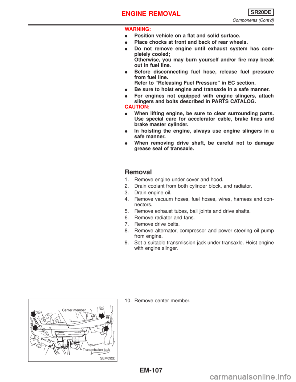
9. Set a suitable transmission jack under transaxle. Hoist engine
with engine slinger.
10. Remove center member.
SEM092D Center member
Transmission jack
ENGINE REMOVALSR20DE
Components (Cont'd)
EM-107
Page 1805 of 2267
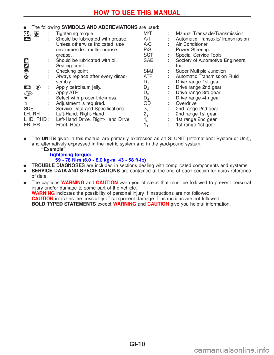
lThe followingSYMBOLS AND ABBREVIATIONSare used:
,: Tightening torque
: Should be lubricated with grease.
Unless otherwise indicated, use
recommended multi-purpose
grease.
: Should be lubricated with oil.
: Sealing point
: Checking point
: Always replace after every disas-
sembly.
pP: Apply petroleum jelly.
: Apply ATF.
H: Select with proper thickness.
I: Adjustment is required.
SDS : Service Data and Specifications
LH, RH : Left-Hand, Right-Hand
LHD, RHD : Left-Hand Drive, Right-Hand Drive
FR, RR : Front, RearM/T : Manual Transaxle/Transmission
A/T : Automatic Transaxle/Transmission
A/C : Air Conditioner
P/S : Power Steering
SST : Special Service Tools
SAE : Society of Automotive Engineers,
Inc.
SMJ : Super Multiple Junction
ATF : Automatic Transmission Fluid
D
1: Drive range 1st gear
D
2: Drive range 2nd gear
D
3: Drive range 3rd gear
D
4: Drive range 4th gear
OD : Overdrive
2
2: 2nd range 2nd gear
2
1: 2nd range 1st gear
1
2: 1st range 2nd gear
1
1: 1st range 1st gear
lTheUNITSgiven in this manual are primarily expressed as an SI UNIT (International System of Unit),
and alternatively expressed in the metric system and in the yard/pound system.
ªExampleº
Tightening torque:
59 - 78 N´m (6.0 - 8.0 kg-m, 43 - 58 ft-lb)
lTROUBLE DIAGNOSESare included in sections dealing with complicated components and systems.
lSERVICE DATA AND SPECIFICATIONSare contained at the end of each section for quick reference
of data.
lThe captionsWARNINGandCAUTIONwarn you of steps that must be followed to prevent personal
injury and/or damage to some part of the vehicle.
WARNINGindicates the possibility of personal injury if instructions are not followed.
CAUTIONindicates the possibility of component damage if instructions are not followed.
BOLD TYPED STATEMENTSexceptWARNINGandCAUTIONgive you helpful information.
HOW TO USE THIS MANUAL
GI-10