1999 NISSAN PRIMERA battery
[x] Cancel search: batteryPage 7 of 2267
Precautions for Supplemental Restraint System
(SRS) ªAIR BAGº and ªSEAT BELT
PRE-TENSIONERº
NCAT0002The Supplemental Restraint System ªAIR BAGº and ªSEAT BELT PRE-TENSIONERº, used along with a seat
belt, help to reduce the risk or severity of injury to the driver and front passenger in a frontal collision. The
Supplemental Restraint System consists of air bag modules (located in the center of the steering wheel and
on the instrument panel on the passenger side), seat belt pre-tensioners, a diagnosis sensor unit, warning
lamp, wiring harness and spiral cable.
In addition to the supplemental air bag modules for a frontal collision, the supplemental side air bag used along
with the seat belt helps to reduce the risk or severity of injury to the driver and front passenger in a side col-
lision. The supplemental side air bag consists of air bag modules (located in the outer side of front seats),
satellite sensor, diagnosis sensor unit (one of components of supplemental air bags for a frontal collision),
wiring harness, warning lamp (one of components of supplemental air bags for a frontal collision). Information
necessary to service the system safely is included in theRS sectionof this Service Manual.
WARNING:
ITo avoid rendering the SRS inoperative, which could increase the risk of personal injury or death
in the event of a collision which would result in air bag inflation, all maintenance must be performed
by an authorized NISSAN dealer.
IImproper maintenance, including incorrect removal and installation of the SRS, can lead to per-
sonal injury caused by unintentional activation of the system.
IDo not use electrical test equipment on any circuit related to the SRS unless instructed to in this
Service Manual. SRS wiring harnesses (except ªSEAT BELT PRE-TENSIONERº connector) can be
identified with yellow harness connector (and with yellow harness protector or yellow insulation
tape before the harness connectors).
Precautions for On Board Diagnostic (OBD)
System of CVT and Engine
NCAT0198The ECM has an on board diagnostic system. It will light up the malfunction indicator (MI) to warn the driver
of a malfunction causing emission deterioration.
CAUTION:
IBe sure to turn the ignition switch ªOFFº and disconnect the negative battery terminal before any
repair or inspection work. The open/short circuit of related switches, sensors, solenoid valves, etc.
will cause the MI to light up.
IBe sure to connect and lock the connectors securely after work. A loose (unlocked) connector will
cause the MI to light up due to an open circuit. (Be sure the connector is free from water, grease,
dirt, bent terminals, etc.)
IBe sure to route and secure the harnesses properly after work. Interference of the harness with a
bracket, etc. may cause the MI to light up due to a short circuit.
IBe sure to connect rubber tubes properly after work. A misconnected or disconnected rubber tube
may cause the MI to light up due to a malfunction of the EGR system or fuel injection system, etc.
IBe sure to erase the unnecessary malfunction information (repairs completed) from the TCM and
ECM before returning the vehicle to the customer.
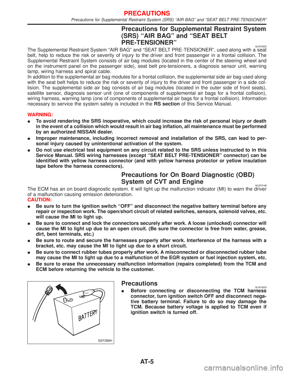
PrecautionsNCAT0003IBefore connecting or disconnecting the TCM harness
connector, turn ignition switch OFF and disconnect nega-
tive battery terminal. Failure to do so may damage the
TCM. Because battery voltage is applied to TCM even if
ignition switch is turned off.
SEF289H
PRECAUTIONS
Precautions for Supplemental Restraint System (SRS) ªAIR BAGº and ªSEAT BELT PRE-TENSIONERº
AT-5
Page 18 of 2267
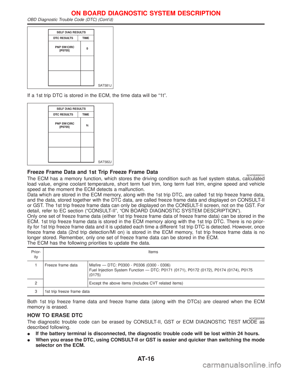
If a 1st trip DTC is stored in the ECM, the time data will be ª1tº.
Freeze Frame Data and 1st Trip Freeze Frame DataNCAT0020S0101The ECM has a memory function, which stores the driving condition such as fuel system status, calculated
load value, engine coolant temperature, short term fuel trim, long term fuel trim, engine speed and vehicle
speed at the moment the ECM detects a malfunction.
Data which are stored in the ECM memory, along with the 1st trip DTC, are called 1st trip freeze frame data,
and the data, stored together with the DTC data, are called freeze frame data and displayed on CONSULT-II
or GST. The 1st trip freeze frame data can only be displayed on the CONSULT-II screen, not on the GST. For
detail, refer to EC section (ªCONSULT-IIº, ªON BOARD DIAGNOSTIC SYSTEM DESCRIPTIONº).
Only one set of freeze frame data (either 1st trip freeze frame data of freeze frame data) can be stored in the
ECM. 1st trip freeze frame data is stored in the ECM memory along with the 1st trip DTC. There is no prior-
ity for 1st trip freeze frame data and it is updated each time a different 1st trip DTC is detected. However, once
freeze frame data (2nd trip detection/MI on) is stored in the ECM memory, 1st trip freeze frame data is no
longer stored. Remember, only one set of freeze frame data can be stored in the ECM.
The ECM has the following priorities to update the data.
Prior-
ityItems
1 Freeze frame data Misfire Ð DTC: P0300 - P0306 (0300 - 0306)
Fuel Injection System Function Ð DTC: P0171 (0171), P0172 (0172), P0174 (0174), P0175
(0175)
2 Except the above items (Includes CVT related items)
3 1st trip freeze frame data
Both 1st trip freeze frame data and freeze frame data (along with the DTCs) are cleared when the ECM
memory is erased.
HOW TO ERASE DTCNCAT0020S02The diagnostic trouble code can be erased by CONSULT-II, GST or ECM DIAGNOSTIC TEST MODE as
described following.
IIf the battery terminal is disconnected, the diagnostic trouble code will be lost within 24 hours.
IWhen you erase the DTC, using CONSULT-II or GST is easier and quicker than switching the mode
selector on the ECM.
SAT581J
SAT582J
ON BOARD DIAGNOSTIC SYSTEM DESCRIPTION
OBD Diagnostic Trouble Code (DTC) (Cont'd)
AT-16
Page 23 of 2267
![NISSAN PRIMERA 1999 Electronic Repair Manual DATA MONITOR MODE (CVT)NCAT0022S04
Item DisplayMonitor item
Description Remarks
TCM input
signalsMain
signals
Vehicle speed sensor
(Secondary speed sensor)VHCL SPEED
SE
[km/h] or [mph] X ÐIVehicle sp NISSAN PRIMERA 1999 Electronic Repair Manual DATA MONITOR MODE (CVT)NCAT0022S04
Item DisplayMonitor item
Description Remarks
TCM input
signalsMain
signals
Vehicle speed sensor
(Secondary speed sensor)VHCL SPEED
SE
[km/h] or [mph] X ÐIVehicle sp](/manual-img/5/57377/w960_57377-22.png)
DATA MONITOR MODE (CVT)NCAT0022S04
Item DisplayMonitor item
Description Remarks
TCM input
signalsMain
signals
Vehicle speed sensor
(Secondary speed sensor)VHCL SPEED
SE
[km/h] or [mph] X ÐIVehicle speed com-
puted from signal of
revolution sensor is dis-
played.When racing engine in ªNº
or ªPº position with vehicle
stationary, CONSULT-II data
may not indicate
0 km/h (0 mph).
Throttle position sensor THRTL POS
SEN
[V]XÐIThrottle position sensor
signal voltage is dis-
played.Ð
CVT fluid temperature
sensorFLUID TEMP
SE
[V]
XÐICVT fluid temperature
sensor signal voltage is
displayed.
ISignal voltage lowers
as fluid temperature
rises.Ð
Battery voltage BATTERY VOLT
[V]XÐISource voltage of TCM
is displayed.Ð
Engine speed ENGINE
SPEED
[rpm] X XIEngine speed, com-
puted from engine
speed signal, is dis-
played.Engine speed display may
not be accurate under
approx. 800 rpm. It may not
indicate 0 rpm even when
engine is not running.
P/N position switch N POSITION
SW
[ON/OFF]XÐION/OFF state com-
puted from signal of
P/N position SW is dis-
played.Ð
R position switch R POSITION
SW
[ON/OFF]XÐION/OFF state com-
puted from signal of R
position SW is dis-
played.Ð
D position switch D POSITION
SW
[ON/OFF]XÐION/OFF state com-
puted from signal of D
position SW is dis-
played.Ð
Sport mode switch S POSITION
SW
[ON/OFF]XÐION/OFF status, com-
puted from signal of
Sport mode SW, is dis-
played.Ð
L position switch L POSITION
SW
[ON/OFF]XÐION/OFF status, com-
puted from signal of L
position SW, is dis-
played.Ð
Closed throttle position
switchCLOSED
THL/SW
[ON/OFF]XÐION/OFF status, com-
puted from signal of
closed throttle position
SW, is displayed.Ð
Wide open throttle position
switchW/O THRL/
P-SW
[ON/OFF]XÐION/OFF status, com-
puted from signal of
wide open throttle posi-
tion SW, is displayed.Ð
ON BOARD DIAGNOSTIC SYSTEM DESCRIPTION
CONSULT-II (Cont'd)
AT-21
Page 29 of 2267
CVT or SPORT indicator lamp*
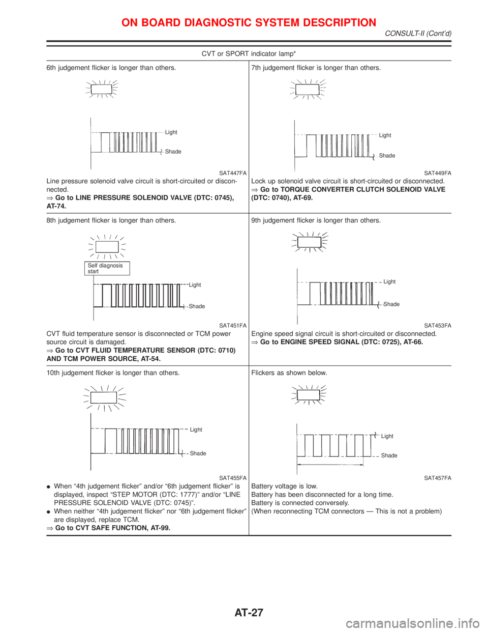
6th judgement flicker is longer than others.
SAT447FA
Line pressure solenoid valve circuit is short-circuited or discon-
nected.
ÞGo to LINE PRESSURE SOLENOID VALVE (DTC: 0745),
AT-74.
Light
Shade
7th judgement flicker is longer than others.
SAT449FA
Lock up solenoid valve circuit is short-circuited or disconnected.
ÞGo to TORQUE CONVERTER CLUTCH SOLENOID VALVE
(DTC: 0740), AT-69.
Light
Shade
8th judgement flicker is longer than others.
SAT451FA
CVT fluid temperature sensor is disconnected or TCM power
source circuit is damaged.
ÞGo to CVT FLUID TEMPERATURE SENSOR (DTC: 0710)
AND TCM POWER SOURCE, AT-54.
Self diagnosis
start
Light
Shade
9th judgement flicker is longer than others.
SAT453FA
Engine speed signal circuit is short-circuited or disconnected.
ÞGo to ENGINE SPEED SIGNAL (DTC: 0725), AT-66.
Light
Shade
10th judgement flicker is longer than others.
SAT455FA Light
Shade
IWhen ª4th judgement flickerº and/or ª6th judgement flickerº is
displayed, inspect ªSTEP MOTOR (DTC: 1777)º and/or ªLINE
PRESSURE SOLENOID VALVE (DTC: 0745)º.
IWhen neither ª4th judgement flickerº nor ª6th judgement flickerº
are displayed, replace TCM.
ÞGo to CVT SAFE FUNCTION, AT-99.Flickers as shown below.
SAT457FA
Battery voltage is low.
Battery has been disconnected for a long time.
Battery is connected conversely.
(When reconnecting TCM connectors Ð This is not a problem)
Light
Shade
ON BOARD DIAGNOSTIC SYSTEM DESCRIPTION
CONSULT-II (Cont'd)
AT-27
Page 33 of 2267
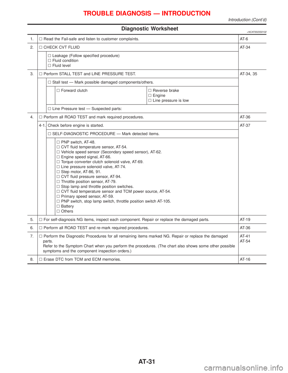
Diagnostic Worksheet=NCAT0023S0102
1.lRead the Fail-safe and listen to customer complaints. AT-6
2.lCHECK CVT FLUIDAT-34
lLeakage (Follow specified procedure)
lFluid condition
lFluid level
3.lPerform STALL TEST and LINE PRESSURE TEST. AT-34, 35
lStall test Ð Mark possible damaged components/others.
lForward clutchlReverse brake
lEngine
lLine pressure is low
lLine Pressure test Ð Suspected parts:
4.lPerform all ROAD TEST and mark required procedures. AT-36
4-1. Check before engine is started.AT-37
lSELF-DIAGNOSTIC PROCEDURE Ð Mark detected items.
lPNP switch, AT-48.
lCVT fluid temperature sensor, AT-54.
lVehicle speed sensor (Secondary speed sensor), AT-62.
lEngine speed signal, AT-66.
lTorque converter clutch solenoid valve, AT-69.
lLine pressure solenoid valve, AT-74.
lStep motor, AT-86, 91.
lCVT fluid pressure sensor, AT-94.
lThrottle position sensor, AT-79.
lStop lamp and throttle position switches.
lCVT fluid temperature sensor and TCM power source, AT-54.
lPrimary speed sensor, AT-59.
lPNP switch, stop lamp switch, throttle position switch AT-105.
lBattery
lOthers
5.lFor self-diagnosis NG items, inspect each component. Repair or replace the damaged parts. AT-19
6.lPerform all ROAD TEST and re-mark required procedures. AT-36
7.lPerform the Diagnostic Procedures for all remaining items marked NG. Repair or replace the damaged
parts.
Refer to the Symptom Chart when you perform the procedures. (The chart also shows some other possible
symptoms and the component inspection orders.)AT-41
AT-54
8.lErase DTC from TCM and ECM memories. AT-16
TROUBLE DIAGNOSIS Ð INTRODUCTION
Introduction (Cont'd)
AT-31
Page 43 of 2267
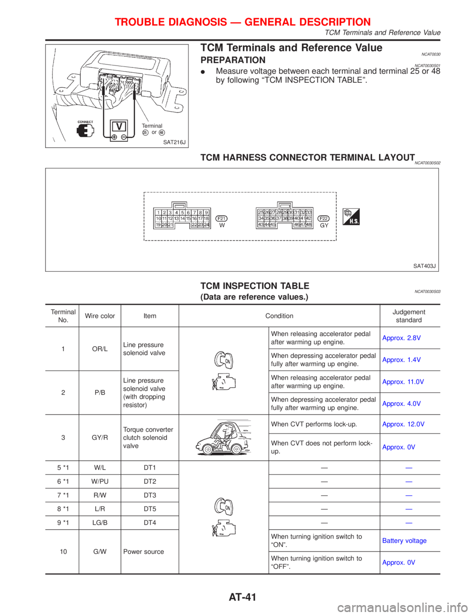
TCM Terminals and Reference ValueNCAT0030PREPARATIONNCAT0030S01IMeasure voltage between each terminal and terminal 25 or 48
by following ªTCM INSPECTION TABLEº.
TCM HARNESS CONNECTOR TERMINAL LAYOUTNCAT0030S02
TCM INSPECTION TABLENCAT0030S03(Data are reference values.)
Terminal
No.Wire color Item ConditionJudgement
standard
1 OR/LLine pressure
solenoid valve
When releasing accelerator pedal
after warming up engine.Approx. 2.8V
When depressing accelerator pedal
fully after warming up engine.Approx. 1.4V
2 P/BLine pressure
solenoid valve
(with dropping
resistor)When releasing accelerator pedal
after warming up engine.Approx. 11.0V
When depressing accelerator pedal
fully after warming up engine.Approx. 4.0V
3 GY/RTorque converter
clutch solenoid
valve
When CVT performs lock-up.Approx. 12.0V
When CVT does not perform lock-
up.Approx. 0V
5 *1 W/L DT1
ÐÐ
6 *1 W/PU DT2 ÐÐ
7 *1 R/W DT3 ÐÐ
8 *1 L/R DT5 ÐÐ
9 *1 LG/B DT4 ÐÐ
10 G/W Power sourceWhen turning ignition switch to
ªONº.Battery voltage
When turning ignition switch to
ªOFFº.Approx. 0V
SAT216J Terminal
p25orp48
SAT403J
TROUBLE DIAGNOSIS Ð GENERAL DESCRIPTION
TCM Terminals and Reference Value
AT-41
Page 44 of 2267
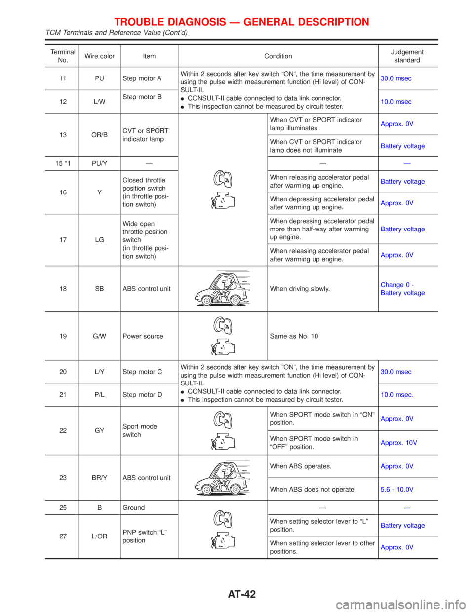
Terminal
No.Wire color Item ConditionJudgement
standard
11 PU Step motor AWithin 2 seconds after key switch ªONº, the time measurement by
using the pulse width measurement function (Hi level) of CON-
SULT-II.
ICONSULT-II cable connected to data link connector.
IThis inspection cannot be measured by circuit tester.30.0 msec
12 L/WStep motor B
10.0 msec
13 OR/BCVT or SPORT
indicator lamp
When CVT or SPORT indicator
lamp illuminatesApprox. 0V
When CVT or SPORT indicator
lamp does not illuminateBattery voltage
15 *1 PU/Y Ð ÐÐ
16 YClosed throttle
position switch
(in throttle posi-
tion switch)When releasing accelerator pedal
after warming up engine.Battery voltage
When depressing accelerator pedal
after warming up engine.Approx. 0V
17 LGWide open
throttle position
switch
(in throttle posi-
tion switch)When depressing accelerator pedal
more than half-way after warming
up engine.Battery voltage
When releasing accelerator pedal
after warming up engine.Approx. 0V
18 SB ABS control unit
When driving slowly.Change 0 -
Battery voltage
19 G/W Power source
Same as No. 10
20 L/Y Step motor CWithin 2 seconds after key switch ªONº, the time measurement by
using the pulse width measurement function (Hi level) of CON-
SULT-II.
ICONSULT-II cable connected to data link connector.
IThis inspection cannot be measured by circuit tester.30.0 msec
21 P/L Step motor D10.0 msec.
22 GYSport mode
switch
When SPORT mode switch in ªONº
position.Approx. 0V
When SPORT mode switch in
ªOFFº position.Approx. 10V
23 BR/Y ABS control unit
When ABS operates.Approx. 0V
When ABS does not operate.5.6 - 10.0V
25 B Ground
ÐÐ
27 L/ORPNP switch ªLº
positionWhen setting selector lever to ªLº
position.Battery voltage
When setting selector lever to other
positions.Approx. 0V
TROUBLE DIAGNOSIS Ð GENERAL DESCRIPTION
TCM Terminals and Reference Value (Cont'd)
AT-42
Page 45 of 2267
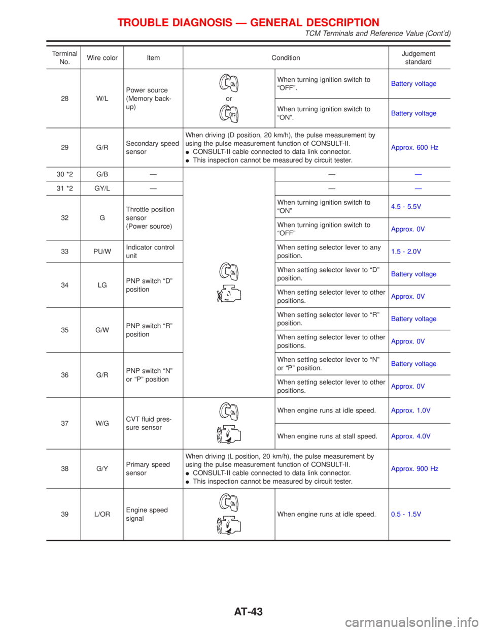
Terminal
No.Wire color Item ConditionJudgement
standard
28 W/LPower source
(Memory back-
up)
or
When turning ignition switch to
ªOFFº.Battery voltage
When turning ignition switch to
ªONº.Battery voltage
29 G/RSecondary speed
sensorWhen driving (D position, 20 km/h), the pulse measurement by
using the pulse measurement function of CONSULT-II.
ICONSULT-II cable connected to data link connector.
IThis inspection cannot be measured by circuit tester.Approx. 600 Hz
30 *2 G/B Ð
ÐÐ
31 *2 GY/L Ð ÐÐ
32 GThrottle position
sensor
(Power source)When turning ignition switch to
ªONº4.5 - 5.5V
When turning ignition switch to
ªOFFºApprox. 0V
33 PU/WIndicator control
unitWhen setting selector lever to any
position.1.5 - 2.0V
34 LGPNP switch ªDº
positionWhen setting selector lever to ªDº
position.Battery voltage
When setting selector lever to other
positions.Approx. 0V
35 G/WPNP switch ªRº
positionWhen setting selector lever to ªRº
position.Battery voltage
When setting selector lever to other
positions.Approx. 0V
36 G/RPNP switch ªNº
or ªPº positionWhen setting selector lever to ªNº
or ªPº position.Battery voltage
When setting selector lever to other
positions.Approx. 0V
37 W/GCVT fluid pres-
sure sensor
When engine runs at idle speed.Approx. 1.0V
When engine runs at stall speed.Approx. 4.0V
38 G/YPrimary speed
sensorWhen driving (L position, 20 km/h), the pulse measurement by
using the pulse measurement function of CONSULT-II.
ICONSULT-II cable connected to data link connector.
IThis inspection cannot be measured by circuit tester.Approx. 900 Hz
39 L/OREngine speed
signal
When engine runs at idle speed.0.5 - 1.5V
TROUBLE DIAGNOSIS Ð GENERAL DESCRIPTION
TCM Terminals and Reference Value (Cont'd)
AT-43