Page 46 of 2267
Terminal
No.Wire color Item ConditionJudgement
standard
41 GYThrottle position
sensor
When depressing accelerator pedal
slowly after warming up engine.
(Voltage rises gradually in response
to throttle position.)Fully-closed
throttle:
Approximately
0.3V
Fully-open
throttle:
Approximately 3V
42 B/WThrottle position
sensor
(Ground)ÐÐ
45 R/G Stop lamp switchWhen depressing brake pedalBattery voltage
When releasing brake pedalApprox. 0V
46 P/LCVT fluid pres-
sure sensor
(Power source)Ð4.5 - 5.5V
47 Y/PUCVT fluid tem-
perature sensorWhen CVT fluid temperature is
20ÉC (68ÉF).Approximately
1.5V
When CVT fluid temperature is
80ÉC (176ÉF).Approximately
0.5V
48 B Ground ÐÐ
*1: This terminal is connected to the ECM.
*2: These terminals are connected to the Data link connector for CONSULT-II.
TROUBLE DIAGNOSIS Ð GENERAL DESCRIPTION
TCM Terminals and Reference Value (Cont'd)
AT-44
Page 47 of 2267
Wiring Diagram Ð CVT Ð MAINNCAT0031
YAT201
BATTERY
ENGINE
CONTROL
MODULE
RELAY
OFFONSTOP
LAMP
SWITCH
FUSE
BLOCK
(J/B)OFFONSTOP
LAMP
SWITCH: Detectable line for DTC
: Non-detectable line for DTC
: LHD models
: RHD models Refer to EL-POWER. FUSE
BLOCK
(J/B)
TCM
(TRANSMISSION
CONTROL
MODULE)
Refer to last page
(foldout page). ECM
TROUBLE DIAGNOSIS FOR POWER SUPPLY
Wiring Diagram Ð CVT Ð MAIN
AT-45
Page 48 of 2267

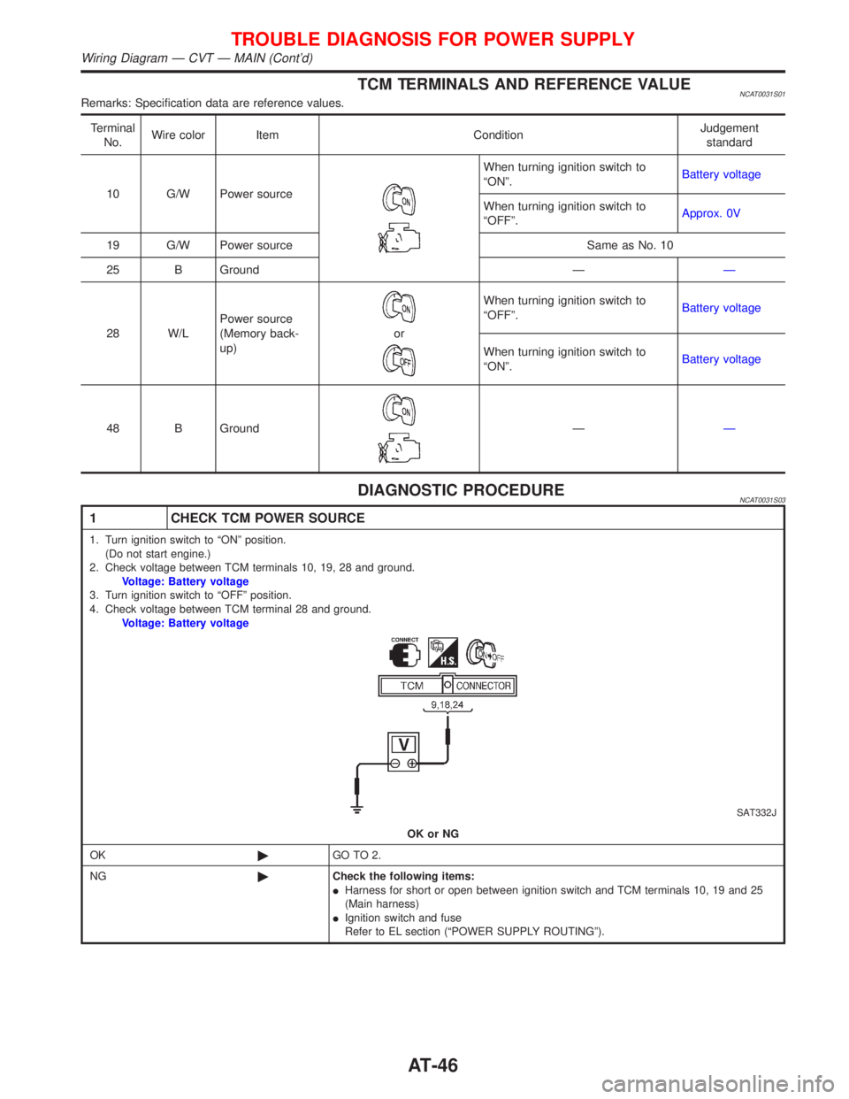
TCM TERMINALS AND REFERENCE VALUENCAT0031S01Remarks: Specification data are reference values.
Terminal
No.Wire color Item ConditionJudgement
standard
10 G/W Power source
When turning ignition switch to
ªONº.Battery voltage
When turning ignition switch to
ªOFFº.Approx. 0V
19 G/W Power source Same as No. 10
25 B Ground ÐÐ
28 W/LPower source
(Memory back-
up)
or
When turning ignition switch to
ªOFFº.Battery voltage
When turning ignition switch to
ªONº.Battery voltage
48 B Ground
ÐÐ
DIAGNOSTIC PROCEDURENCAT0031S03
1 CHECK TCM POWER SOURCE
1. Turn ignition switch to ªONº position.
(Do not start engine.)
2. Check voltage between TCM terminals 10, 19, 28 and ground.
Voltage: Battery voltage
3. Turn ignition switch to ªOFFº position.
4. Check voltage between TCM terminal 28 and ground.
Voltage: Battery voltage
SAT332J
OK or NG
OK©GO TO 2.
NG©Check the following items:
IHarness for short or open between ignition switch and TCM terminals 10, 19 and 25
(Main harness)
IIgnition switch and fuse
Refer to EL section (ªPOWER SUPPLY ROUTINGº).
TROUBLE DIAGNOSIS FOR POWER SUPPLY
Wiring Diagram Ð CVT Ð MAIN (Cont'd)
AT-46
Page 50 of 2267

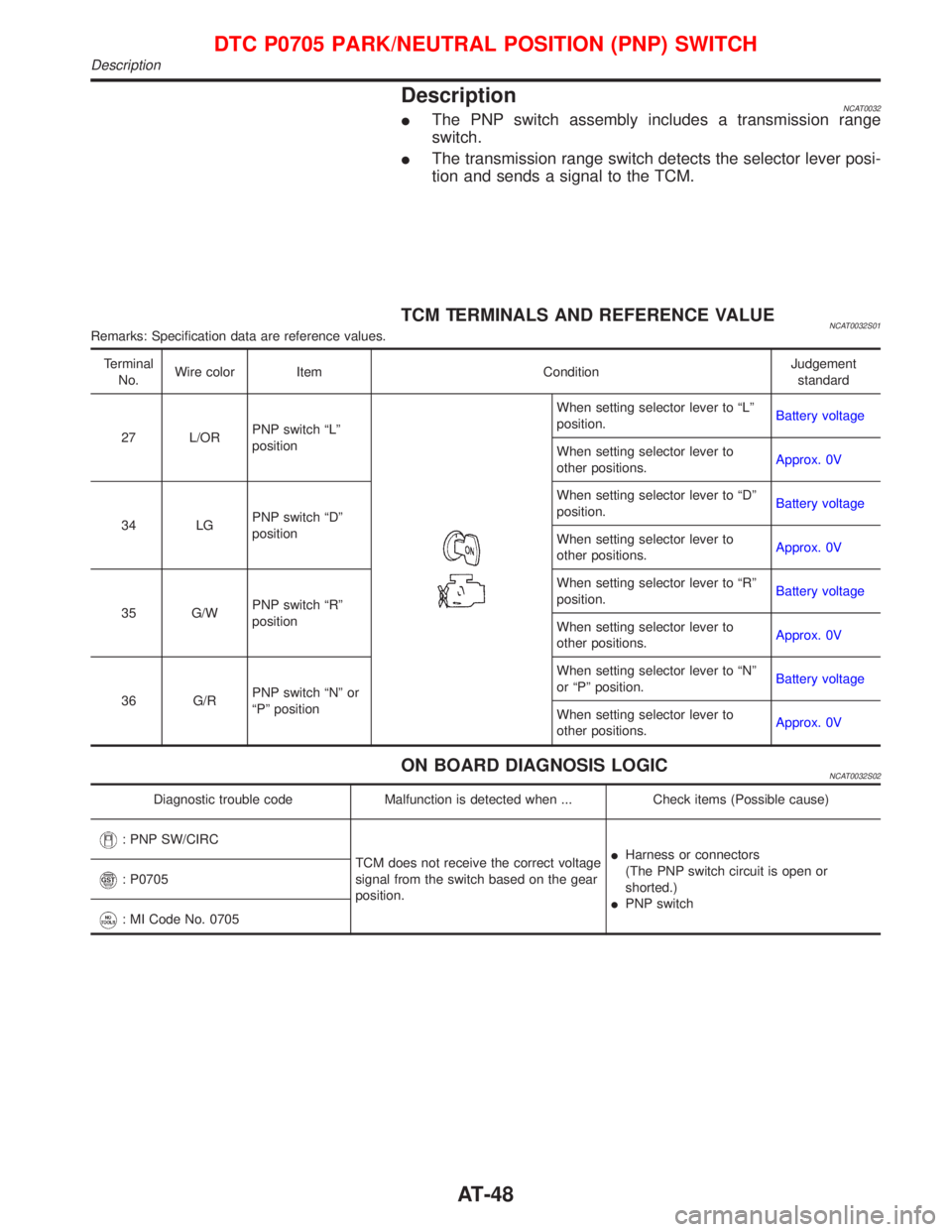
DescriptionNCAT0032IThe PNP switch assembly includes a transmission range
switch.
IThe transmission range switch detects the selector lever posi-
tion and sends a signal to the TCM.
TCM TERMINALS AND REFERENCE VALUENCAT0032S01Remarks: Specification data are reference values.
Terminal
No.Wire color Item ConditionJudgement
standard
27 L/ORPNP switch ªLº
position
When setting selector lever to ªLº
position.Battery voltage
When setting selector lever to
other positions.Approx. 0V
34 LGPNP switch ªDº
positionWhen setting selector lever to ªDº
position.Battery voltage
When setting selector lever to
other positions.Approx. 0V
35 G/WPNP switch ªRº
positionWhen setting selector lever to ªRº
position.Battery voltage
When setting selector lever to
other positions.Approx. 0V
36 G/RPNP switch ªNº or
ªPº positionWhen setting selector lever to ªNº
or ªPº position.Battery voltage
When setting selector lever to
other positions.Approx. 0V
ON BOARD DIAGNOSIS LOGICNCAT0032S02
Diagnostic trouble code Malfunction is detected when ... Check items (Possible cause)
: PNP SW/CIRC
TCM does not receive the correct voltage
signal from the switch based on the gear
position.IHarness or connectors
(The PNP switch circuit is open or
shorted.)
IPNP switch
: P0705
: MI Code No. 0705
DTC P0705 PARK/NEUTRAL POSITION (PNP) SWITCH
Description
AT-48
Page 53 of 2267

Diagnostic ProcedureNCAT0033
1 CHECK PNP SWITCH CIRCUIT (With CONSULT-II)
With CONSULT-II
1. Turn ignition switch to ªONº position.
(Do not start engine.)
2. Select ªECU INPUT SIGNALSº in ªDATA MONITORº mode for ªCVTº with CONSULT-II.
SAT651J3. Read out ªP/Nº, ªRº, ªDº and ªLº position switches moving selector lever to each position.
Check the signal of the selector lever position is indicated properly.
OK or NG
OK©GO TO 3.
NG©Check the following items:
IPNP switch
Refer to ªComponent Inspectionº, AT-53.
IHarness for short or open between ignition switch and PNP switch (Main harness)
IHarness for short or open between PNP switch and TCM (Main harness)
IIgnition switch and fuse
Refer to EL section (ªPOWER SUPPLY ROUTINGº).
IDiode (P, N positions)
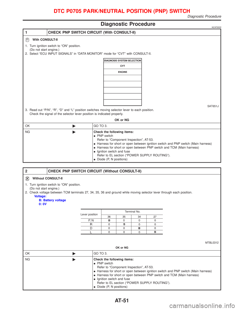
2 CHECK PNP SWITCH CIRCUIT (Without CONSULT-II)
Without CONSULT-II
1. Turn ignition switch to ªONº position.
(Do not start engine.)
2. Check voltage between TCM terminals 27, 34, 35, 36 and ground while moving selector lever through each position.
Voltage:
B: Battery voltage
0: 0V
MTBL0312 Terminal No.
Lever position
OK or NG
OK©GO TO 3.
NG©Check the following items:
IPNP switch
Refer to ªComponent Inspectionº, AT-53.
IHarness for short or open between ignition switch and PNP switch (Main harness)
IHarness for short or open between PNP switch and TCM (Main harness)
IIgnition switch and fuse
Refer to EL section (ªPOWER SUPPLY ROUTINGº).
IDiode (P, N positions)
DTC P0705 PARK/NEUTRAL POSITION (PNP) SWITCH
Diagnostic Procedure
AT-51
Page 75 of 2267
Component InspectionNCAT0057TORQUE CONVERTER CLUTCH SOLENOID VALVENCAT0057S01IFor removal, refer to AT-116.
Resistance CheckNCAT0057S0101ICheck resistance between two terminals.
Solenoid valve Terminal No.Resistance
(Approx.)
Torque converter
clutch solenoid
valve9Ground of TCC
solenoid valve10-16W
Operation CheckNCAT0057S0102ICheck solenoid valve by listening for its operating sound while
applying battery voltage to the terminal and ground of TCC
solenoid valve.
SAT684J To torque converter clutch solenoid valve
SAT685J To torque converter clutch solenoid valve
DTC P0740 TORQUE CONVERTER CLUTCH SOLENOID VALVE
Component Inspection
AT-73
Page 80 of 2267
Component Inspection=NCAT0063LINE PRESSURE SOLENOID VALVENCAT0063S01IFor removal, refer to AT-116.
Resistance CheckNCAT0063S0101ICheck resistance between two terminals.
Solenoid valve Terminal No.Resistance
(Approx.)
Line pressure
solenoid valve8Ground of line
pressure solenoid
valve2.5-5W
Operation CheckNCAT0063S0102ICheck solenoid valve by listening for its operating sound while
applying battery voltage to the terminal and ground of line
pressure solenoid valve.
DROPPING RESISTORNCAT0063S02ICheck resistance between two terminals.
Resistance:
11.2 - 12.8W
SAT686J To line pressure
solenoid valve
SAT687J To line pressure
solenoid valve
SAT444J
DTC P0745 LINE PRESSURE SOLENOID VALVE
Component Inspection
AT-78
Page 81 of 2267

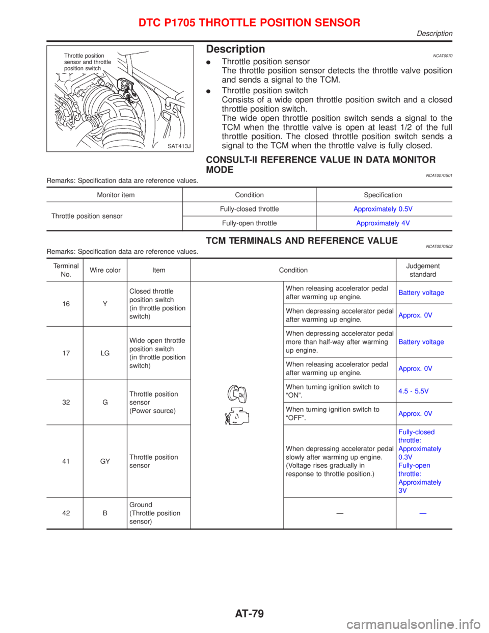
DescriptionNCAT0070IThrottle position sensor
The throttle position sensor detects the throttle valve position
and sends a signal to the TCM.
IThrottle position switch
Consists of a wide open throttle position switch and a closed
throttle position switch.
The wide open throttle position switch sends a signal to the
TCM when the throttle valve is open at least 1/2 of the full
throttle position. The closed throttle position switch sends a
signal to the TCM when the throttle valve is fully closed.
CONSULT-II REFERENCE VALUE IN DATA MONITOR
MODE
NCAT0070S01Remarks: Specification data are reference values.
Monitor item Condition Specification
Throttle position sensorFully-closed throttleApproximately 0.5V
Fully-open throttleApproximately 4V
TCM TERMINALS AND REFERENCE VALUENCAT0070S02Remarks: Specification data are reference values.
Terminal
No.Wire color Item ConditionJudgement
standard
16 YClosed throttle
position switch
(in throttle position
switch)
When releasing accelerator pedal
after warming up engine.Battery voltage
When depressing accelerator pedal
after warming up engine.Approx. 0V
17 LGWide open throttle
position switch
(in throttle position
switch)When depressing accelerator pedal
more than half-way after warming
up engine.Battery voltage
When releasing accelerator pedal
after warming up engine.Approx. 0V
32 GThrottle position
sensor
(Power source)When turning ignition switch to
ªONº.4.5 - 5.5V
When turning ignition switch to
ªOFFº.Approx. 0V
41 GYThrottle position
sensorWhen depressing accelerator pedal
slowly after warming up engine.
(Voltage rises gradually in
response to throttle position.)Fully-closed
throttle:
Approximately
0.3V
Fully-open
throttle:
Approximately
3V
42 BGround
(Throttle position
sensor)ÐÐ
SAT413J Throttle position
sensor and throttle
position switch
DTC P1705 THROTTLE POSITION SENSOR
Description
AT-79