1999 NISSAN PRIMERA airbag
[x] Cancel search: airbagPage 254 of 2267
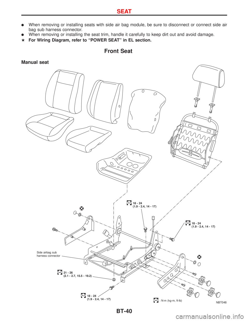
lWhen removing or installing seats with side air bag module, be sure to disconnect or connect side air
bag sub harness connector.
lWhen removing or installing the seat trim, handle it carefully to keep dirt out and avoid damage.
HFor Wiring Diagram, refer to ªPOWER SEATº in EL section.
Front Seat
NBT048
18-24
(1.9 - 2.4, 14 - 17)
18-24
(1.9 - 2.4, 14 - 17)
18-24
(1.9 - 2.4, 14 - 17)
: N´m (kg-m, ft-lb)
21-26
(2.1 - 2.7, 15.5 - 19.2)
Manual seat
Side airbag sub
harness connector
SEAT
BT-40
Page 255 of 2267
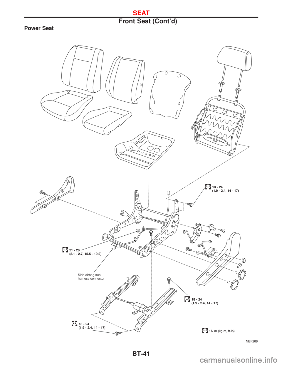
Power Seat
NBF266
18-24
(1.9 - 2.4, 14 - 17)
18-24
(1.9 - 2.4, 14 - 17)
18-24
(1.9 - 2.4, 14 - 17)
: N´m (kg-m, ft-lb)
21-26
(2.1 - 2.7, 15.5 - 19.2)
Side airbag sub
harness connector
SEAT
Front Seat (Cont'd)
BT-41
Page 1155 of 2267
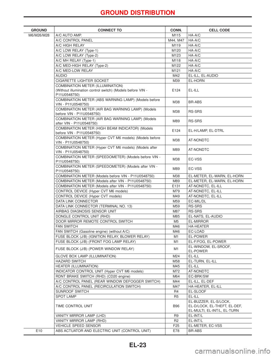
GROUND CONNECT TO CONN. CELL CODE
M6/M26/M28 A/C AUTO AMP. M115 HA-A/C
A/C CONTROL PANEL M44, M47 HA-A/C
A/C HIGH RELAY M119 HA-A/C
A/C LOW RELAY (Type-1) M120 HA-A/C
A/C LOW RELAY (Type-2) M123 HA-A/C
A/C MH RELAY (Type-1) M118 HA-A/C
A/C MED-HIGH RELAY (Type-2) M122 HA-A/C
A/C MED-LOW RELAY M121 HA-A/C
AUDIO M42 EL-ILL, EL-AUDIO
CIGARETTE LIGHTER SOCKET M39 EL-HORN
COMBINATION METER (ILLUMINATION)
(Without illumination control switch) (Models before VIN -
P11U0548750)E124 EL-ILL
COMBINATION METER (ABS WARNING LAMP) (Models before
VIN - P11U0548750)M38 BR-ABS
COMBINATION METER (AIR BAG WARNING LAMP) (Models
before VIN - P11U0548750)M38 RS-SRS
COMBINATION METER (AIR BAG WARNING LAMP) (Models
after VIN - P11U0548750)M89 RS-SRS
COMBINATION METER (HIGH BEAM INDICATOR) (Models
before VIN - P11U0548750)E124 EL-H/LAMP, EL-DTRL
COMBINATION METER (Hyper CVT M6 models) (Models before
VIN - P11U0548750)M38 AT-NONDTC
COMBINATION METER (Hyper CVT M6 models) (Models after
VIN - P11U0548750)M89 AT-NONDTC
COMBINATION METER (SPEEDOMETER) (Models before VIN -
P11U0548750)M38 EC-VSS
COMBINATION METER (SPEEDOMETER) (Models after VIN -
P11U0548750)M89 EC-VSS
COMBINATION METER (Models before VIN - P11U0548750) M38 EL-METER, EL-WARN, EL-HORN
COMBINATION METER (Models after VIN - P11U0548750) M89 EL-METER, EL-WARN, EL-HORN
COMBINATION METER (Models after VIN - P11U0548750) E131 AT-NONDTC, EL-ILL
CONTROL DEVICE (Hyper CVT M6 models) M79 AT-NONDTC, EL-ILL
CONTROL DEVICE (Hyper CVT models) M49 AT-NONDTC, EL-ILL
DATA LINK CONNECTOR M59 EC-MIL/DL
DATA LINK CONNECTOR (TERMINAL NO. 13) M59 RS-SRS
AIRBAG DIAGNOSIS SENSOR UNIT M87 RS-SRS
DONGLE CONTROL UNIT (RHD) M85 EL-NATS, EL-AUDIO
DOOR MIRROR REMOTE CONTROL SWITCH M5 EL-MIRROR
FAN SWITCH M46 HA-HEATER
FAN SWITCH (Gasoline engine) (without A/C) M46 EC-LOAD
FUSE BLOCK (J/B) (IGNITION RELAY, BLOWER RELAY) M1 EL-POWER
FUSE BLOCK (J/B) (FRONT FOG LAMP RELAY) M1 EL-F/FOG, EL-POWER
FUSE BLOCK (J/B) (POWER WINDOW RELAY) M1EL-WINDOW, EL-SROOF,
EL-POWER
GLOVE BOX LAMP (ILLUMINATION) M24 EL-ILL
HAZARD SWITCH M58 EL-TURN, EL-ILL
HEATER (ILLUMINATION) M45 EL-ILL
INDICATOR CONTROL UNIT (Hyper CVT M6 models) M72 AT-NONDTC
RDNT BRAKE SWITCH (RHD) (CD20 engine) M64 EC-BRK/SW
A/C CONTROL PANEL (REAR WINDOW DEFOGGER SWITCH) M44 EL-ILL, EL-DEF
A/C CONTROL PANEL (RECIRCULATION SWITCH) M47 HA-HEATER, EL-ILL
SUNROOF SWITCH R4 EL-SLOOF
SPOT LAMP R5 EL-ILL
TIME CONTROL UNIT B96EL-BUZZER, EL-S/LOCK,
EL-D/LOCK, EL-THEFT, EL-DEF,
EL-MULTI, EL-INT/L, EL-TURN
VANITY MIRROR LAMP (LHD) R9 EL-INT/L
VANITY MIRROR LAMP (RHD) R2 EL-INT/L
VEHICLE SPEED SENSOR F25 EL-METER, EC-VSS
E10 ABS ACTUATOR AND ELECTRIC UNIT (CONTROL UNIT) E78 BR-ABS
GROUND DISTRIBUTION
EL-23
Page 2192 of 2267
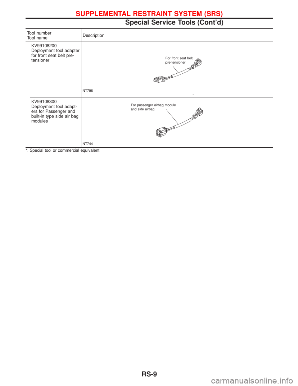
Tool number
Tool nameDescription
KV99108200
Deployment tool adapter
for front seat belt pre-
tensioner
NT796For front seat belt
- pre-tensioner
KV99108300
Deployment tool adapt-
ers for Passenger and
built-in type side air bag
modules
NT744For passenger airbag module
and side airbag
*: Special tool or commercial equivalent
SUPPLEMENTAL RESTRAINT SYSTEM (SRS)
Special Service Tools (Cont'd)
RS-9
Page 2195 of 2267
Maintenance Items
CAUTION:
Do not use electrical test equipment to check SRS circuit.
1. Check operation of ªAIR BAGº warning lamp.
After turning ignition key to ªONº position, the ªAIR BAGº
warning lamp illuminates. The ªAIR BAGº warning lamp will
go off after about 7 seconds if no malfunction is detected.
If any of the following warning lamp conditions occur, imme-
diately check the air bag system. Refer to ªSRS-Operation
Checkº for details. (RS-37)
lThe ªAIR BAGº warning lamp does not come on when the
ignition switch is turned ªONº.
lThe ªAIR BAGº warning lamp does not go off about 7 sec-
onds after the ignition switch is turned ªONº.
lThe ªAIR BAGº warning lamp blinks about 7 seconds after
the ignition switch is turned ªONº.
2. Visually check SRS components.
(1) Diagnosis sensor unit
lCheck diagnosis sensor unit and bracket for dents, cracks or
deformities.
lCheck connectors for damage, and terminals for deformities.
(2) Air bag module and steering wheel
lRemove air bag module from steering wheel, instrument
panel or seat back. Check harness cover and connectors for
damage, terminals for deformities, and harness for binding.
lInstall driver's air bag module to steering wheel to check fit
or alignment with the wheel.
lCheck steering wheel for excessive free play.
lInstall passenger's air bag module to instrument panel to
check fit or alignment with the instrument panel.
lInstall side air bag module to seatback to check fit and align-
ment with the seat.
(3) Spiral cable
lCheck spiral cable for dents, cracks, or deformities.
lCheck connectors and protective tape for damage.
lCheck steering wheel for noise, binding or heavy operation.
(4) Main harness, body harness and air bag harness
lCheck connectors for poor connections, damage, and termi-
nals for deformities.
lCheck harnesses for binding, chafing or cuts.
(5) Seat belt pre-tensioner
lCheck harness cover and connectors for damage, terminals
for deformities, and harness for binding.
lCheck belts for damage and anchors for loose mounting.
lCheck retractor for smooth operation.
lPerform self-diagnosis for seat belt pre-tensioner using ªAIR
BAGº warning lamp or CONSULT-II. Refer to ªSRS Operation
Checkº for details. (RS-37)
(6) Side airbag (Satellite) sensor
lCheck Side airbag (Satellite) sensor (including bracket por-
tion) for dents, cracks or deformities.
lCheck connectors for damage, and terminals for deformities.
SRS797-A
SUPPLEMENTAL RESTRAINT SYSTEM (SRS)
RS-12
Page 2212 of 2267
HOW TO CHANGE SELF-DIAGNOSIS MODE
With CONSULT-II
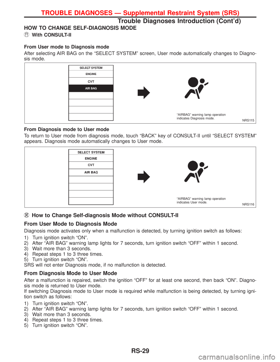
From User mode to Diagnosis mode
After selecting AIR BAG on the ªSELECT SYSTEMº screen, User mode automatically changes to Diagno-
sis mode.
From Diagnosis mode to User mode
To return to User mode from diagnosis mode, touch ªBACKº key of CONSULT-II until ªSELECT SYSTEMº
appears. Diagnosis mode automatically changes to User mode.
How to Change Self-diagnosis Mode without CONSULT-II
From User Mode to Diagnosis Mode
Diagnosis mode activates only when a malfunction is detected, by turning ignition switch as follows:
1) Turn ignition switch ªONº.
2) After ªAIR BAGº warning lamp lights for 7 seconds, turn ignition switch ªOFFº within 1 second.
3) Wait more than 3 seconds.
4) Repeat steps 1 to 3 three times.
5) Turn ignition switch ªONº.
SRS will not enter Diagnosis mode, if no malfunction is detected.
From Diagnosis Mode to User Mode
After a malfunction is repaired, switch the ignition ªOFFº for at least one second, then back ªONº. Diagno-
sis mode is returned to User mode.
If switching Diagnosis mode to User mode is required while malfunction is being detected, by turning igni-
tion switch as follows:
1) Turn ignition switch ªONº.
2) After ªAIR BAGº warning lamp lights for 7 seconds, turn ignition switch ªOFFº within 1 second.
3) Wait more than 3 seconds.
4) Repeat steps 1 to 3 three times.
5) Turn ignition switch ªONº.
NRS115 ªAIRBAGº warning lamp operation
indicates Diagnosis mode.
NRS116 ªAIRBAGº warning lamp operation
indicates User mode.
TROUBLE DIAGNOSES Ð Supplemental Restraint System (SRS)
Trouble Diagnoses Introduction (Cont'd)
RS-29
Page 2221 of 2267
Trouble Diagnoses with CONSULT-II
DIAGNOSTIC PROCEDURE 2
Inspecting SRS malfunctioning parts by using CONSULT-II
Ð Diagnosis mode
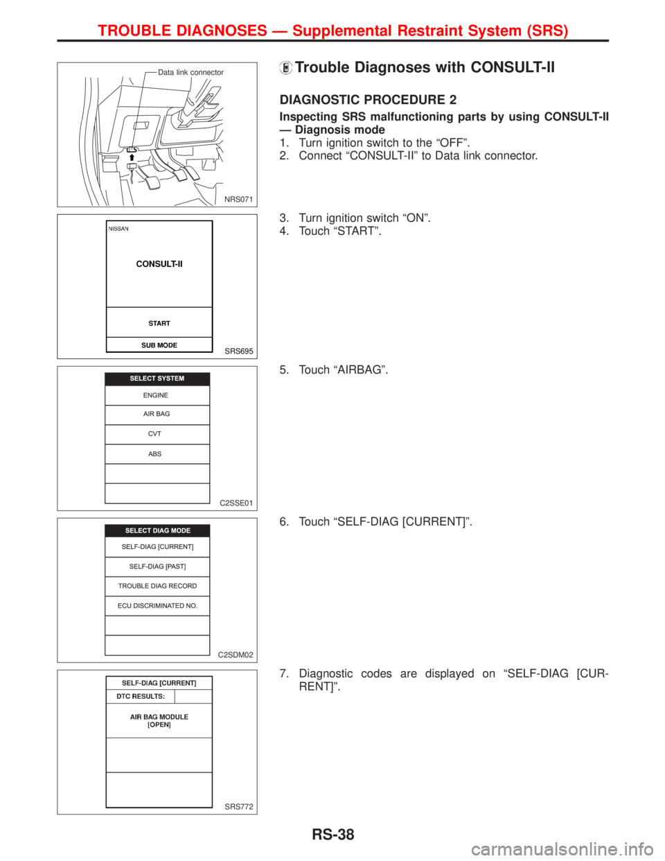
1. Turn ignition switch to the ªOFFº.
2. Connect ªCONSULT-IIº to Data link connector.
3. Turn ignition switch ªONº.
4. Touch ªSTARTº.
5. Touch ªAIRBAGº.
6. Touch ªSELF-DIAG [CURRENT]º.
7. Diagnostic codes are displayed on ªSELF-DIAG [CUR-
RENT]º.
NRS071 Data link connector
SRS695
C2SSE01
C2SDM02
SRS772
TROUBLE DIAGNOSES Ð Supplemental Restraint System (SRS)
RS-38
Page 2222 of 2267
![NISSAN PRIMERA 1999 Electronic Repair Manual If no malfunction is detected on ªSELF-DIAG [CURRENT]º but
malfunction is indicated by the ªAIR BAGº, warning lamp, go to
DIAGNOSTIC PROCEDURE 4, page RS-43, to diagnose the
following situations:
NISSAN PRIMERA 1999 Electronic Repair Manual If no malfunction is detected on ªSELF-DIAG [CURRENT]º but
malfunction is indicated by the ªAIR BAGº, warning lamp, go to
DIAGNOSTIC PROCEDURE 4, page RS-43, to diagnose the
following situations:](/manual-img/5/57377/w960_57377-2221.png)
If no malfunction is detected on ªSELF-DIAG [CURRENT]º but
malfunction is indicated by the ªAIR BAGº, warning lamp, go to
DIAGNOSTIC PROCEDURE 4, page RS-43, to diagnose the
following situations:
lSelf-diagnostic result ªSELF-DIAG [PAST]º (previously
stored in the memory) might not be erased after repair.
lThe SRS system malfunctions intermittently.
8. Touch ªPRINTº.
9. Compare diagnostic codes to ªCONSULT-II Diagnostic Code
Chartº, page RS-39.
10. Touch ªBACKº key of CONSULT-II until ªSELECT SYSTEM º
appears in order to return to User mode from Diagnosis
mode.
11. Turn ignition switch ªOFFº, then turn off and disconnect CON-
SULT-II and both battery cables.
12. Repair the system as outlined by the ªRepair orderº in ªCON-
SULT-II Diagnostic Code Chartº, that corresponds to the self-
diagnostic result. For replacement procedure of component
parts, refer to RS-13.
13. After repairing the system, go to DIAGNOSTIC PROCE-
DURE 3, page RS-42 for final checking.
CONSULT-II Diagnostic Code Chart
(ªSELF-DIAGNOSISº)
Diagnostic item ExplanationRepair order
Recheck SRS at each
replacement.
NO DTC IS DETECTED. When malfunction is indi-
cated by the ªAIR BAGº
warning lamp in User mode
lLow battery voltage (Less
than 9V).lGo to DIAGNOSTIC PRO-
CEDURE 3 (RS-42) after
charging battery.
lSelf-diagnostic result
ªSELF-DIAG [PAST]º (pre-
viously stored in the
memory) might not be
erased after repair.
lIntermittent malfunction has
been detected in the past.Go to DIAGNOSTIC PROCE-
DURE 4 (RS-43).
No malfunction is detected.
lGo to DIAGNOSTIC PRO-
CEDURE 3 (RS-42).
AIRBAG MODULE
[OPEN]
lDriver's air bag module circuit is open. (including the spiral
cable)1. Visually check the wiring
harness connection.
2. Replace the harness if it
has visible damage.
3. Replace driver's air bag
module.
(Before disposing of it, it
must be deployed.)
4. Replace the spiral cable.
5. Replace the diagnosis
sensor unit.
6. Replace the related har-
ness.
C2SDC02
TROUBLE DIAGNOSES Ð Supplemental Restraint System (SRS)
Trouble Diagnoses with CONSULT-II
(Cont'd)
RS-39