1999 NISSAN PRIMERA airbag
[x] Cancel search: airbagPage 2223 of 2267
![NISSAN PRIMERA 1999 Electronic Repair Manual Diagnostic item ExplanationRepair order
Recheck SRS at each
replacement.
AIRBAG MODULE
[VB-SHORT]
lDrivers air bag module circuit is shorted to a power supply
circuit. (including the spiral cable)1.](/manual-img/5/57377/w960_57377-2222.png "NISSAN PRIMERA 1999 Electronic Repair Manual Diagnostic item ExplanationRepair order
Recheck SRS at each
replacement.
AIRBAG MODULE
[VB-SHORT]
lDrivers air bag module circuit is shorted to a power supply
circuit. (including the spiral cable)1.")
Diagnostic item ExplanationRepair order
Recheck SRS at each
replacement.
AIRBAG MODULE
[VB-SHORT]
lDriver's air bag module circuit is shorted to a power supply
circuit. (including the spiral cable)1. Visually check the wiring
harness connection.
2. Replace the harness if it
has visible damage.
3. Replace the spriral cable.
4. Replace driver's air bag
module.
(Before disposing of it, it
must be deployed.)
5. Replace the diagnosis
sensor unit.
6. Replace the related har-
ness. AIRBAG MODULE
[GND-SHORT]
lDriver's air bag module circuit is shorted to ground. (includ-
ing the spiral cable)
AIRBAG MODULE
[SHORT]
lDriver's air bag module circuits are shorted to each other.
ASSIST A/B MODULE
[VB/SHORT]
lPassenger's air bag module circuit is shorted to some
power supply circuit.1. Visually check the wiring
harness connection.
2. Replace the harness if it
has visible damage.
3. Replace passenger's air
bag module. (Before dis-
posal of it, it must be
deployed.)
4. Replace the diagnosis
sensor unit.
5. Replace the related har-
ness. ASSIST A/B MODULE
[OPEN]
lPassenger's air bag module circuit is open.
ASSIST A/B MODULE
[GND-SHORT]
lPassenger's air bag module circuit is shorted to ground.
ASSIST A/B MODULE
[SHORT]
lPassenger's air bag module circuits are shorted to each
other.
SIDE MODULE LH
[OPEN]
lSide air bag module (LH) circuit is open. 1. Visually check the wiring
harness connection.
2. Replace the harness if it
has visible damage.
3. Replace the side air bag
module (LH). (Before
disposal, it must be
deployed.)
4. Replace the diagnosis
sensor unit.
5. Replace the related har-
ness. SIDE MODULE LH
[VB-SHORT]
lSide air bag module (LH) circuit is shorted to some power
supply circuits.
SIDE MODULE LH
[GND-SHORT]
lSide air bag module (LH) circuit is shorted to ground.
SIDE MODULE LH
[SHORT]
lSide air bag module (LH) circuits are shorted to each other.
SIDE MODULE RH
[OPEN]
lSide air bag module (RH) circuit is open. 1. Visually check the wiring
harness connection.
2. Replace the harness if it
has visible damage.
3. Replace the side air bag
module (RH). (Before
disposal, it must be
deployed.)
4. Replace the diagnosis
sensor unit.
5. Replace the related har-
ness. SIDE MODULE RH
[VB-SHORT]
lSide air bag module (RH) circuit is shorted to some power
supply circuits.
SIDE MODULE RH
[GND-SHORT]
lSide air bag module (RH) circuit is shorted to ground.
SIDE MODULE RH
[SHORT]
lSide air bag module (RH) circuits are shorted to each
other.
SATELLITE SENS LH
[UNIT FAIL]
SATELLITE SENS LH
[COMM FAIL]
lSatellite sensor (LH) 1. Visually check the wiring
harness connection.
2. Replace the harness if it
has visible damage.
3. Replace the satellite sen-
sor (LH).
4. Replace the diagnosis
sensor unit.
5. Replace the related har-
ness.
TROUBLE DIAGNOSES Ð Supplemental Restraint System (SRS)
Trouble Diagnoses with CONSULT-II
(Cont'd)
RS-40
Page 2225 of 2267
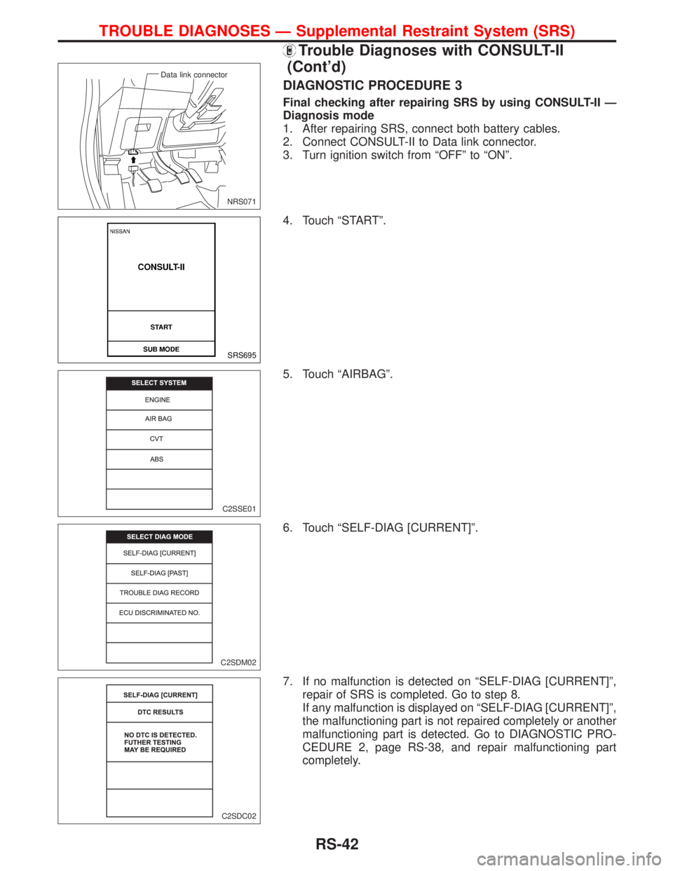
DIAGNOSTIC PROCEDURE 3
Final checking after repairing SRS by using CONSULT-II Ð
Diagnosis mode
1. After repairing SRS, connect both battery cables.
2. Connect CONSULT-II to Data link connector.
3. Turn ignition switch from ªOFFº to ªONº.
4. Touch ªSTARTº.
5. Touch ªAIRBAGº.
6. Touch ªSELF-DIAG [CURRENT]º.
7. If no malfunction is detected on ªSELF-DIAG [CURRENT]º,
repair of SRS is completed. Go to step 8.
If any malfunction is displayed on ªSELF-DIAG [CURRENT]º,
the malfunctioning part is not repaired completely or another
malfunctioning part is detected. Go to DIAGNOSTIC PRO-
CEDURE 2, page RS-38, and repair malfunctioning part
completely.
NRS071 Data link connector
SRS695
C2SSE01
C2SDM02
C2SDC02
TROUBLE DIAGNOSES Ð Supplemental Restraint System (SRS)
Trouble Diagnoses with CONSULT-II
(Cont'd)
RS-42
Page 2229 of 2267
![NISSAN PRIMERA 1999 Electronic Repair Manual Intermittent Malfunction Diagnostic Code Chart
(ªSELF DIAG [PAST]º or ªTROUBLE DIAG RECORDº)
Diagnostic item Explanation Repair order
NO DTC IS DETECTED. When malfunction is indi-
cated by the ªA](/manual-img/5/57377/w960_57377-2228.png "NISSAN PRIMERA 1999 Electronic Repair Manual Intermittent Malfunction Diagnostic Code Chart
(ªSELF DIAG [PAST]º or ªTROUBLE DIAG RECORDº)
Diagnostic item Explanation Repair order
NO DTC IS DETECTED. When malfunction is indi-
cated by the ªA")
Intermittent Malfunction Diagnostic Code Chart
(ªSELF DIAG [PAST]º or ªTROUBLE DIAG RECORDº)
Diagnostic item Explanation Repair order
NO DTC IS DETECTED. When malfunction is indi-
cated by the ªAIR BAGº
warning lamp in User mode
lLow battery voltage (Less
than 9V).lGo to DIAGNOSTIC PRO-
CEDURE 3 (RS-42) after
charging battery.
No malfunction is detected.
lGo to DIAGNOSTIC PRO-
CEDURE 3 (RS-42).
AIRBAG MODULE
[OPEN]
lDriver's air bag module circuit is open. (including the spiral
cable)1. Visually check the wiring
harness connection.
2. Replace the harness if it
has visible damage.
3. If the harness check result
is OK, replace driver's air
bag module (Before dis-
posal of it, it must be
deployed.), diagnosis sen-
sor unit and spiral cable. AIRBAG MODULE
[VB-SHORT]
lDriver's air bag module circuit is shorted to some power
supply circuit. (including the spiral cable)
AIRBAG MODULE
[GND-SHORT]
lDriver's air bag module circuit is shorted to ground. (includ-
ing the spiral cable)
AIRBAG MODULE
[SHORT]
lDriver's air bag module circuits are shorted to each other.
ASSIST A/B MODULE
[VB/SHORT]
lPassenger's air bag module circuit is shorted to some
power supply circuit.1. Visually check the wiring
harness connection.
2. Replace the air bag har-
ness if it has visible dam-
age.
3. If the harness check result
is OK, replace front air
bag module (Before dis-
posal of it, it must be
deployed.), and diagnosis
sensor unit. ASSIST A/B MODULE
[OPEN]
lPassenger's air bag module is open.
ASSIST A/B MODULE
[GND-SHORT]
lPassenger's air bag module circuit is shorted to ground.
ASSIST A/B MODULE
[SHORT]
lPassenger's air bag module circuits are shorted to each
other.
SIDE MODULE LH
[OPEN]
lSide air bag module (LH) circuit is open. 1. Visually check the wiring
harness connection.
2. Replace the harness if it
has visible damage.
3. If the harness check is
OK, replace the diagnosis
sensor unit and side air
bag module (LH). (Before
disposing the side air bag
module (LH), it must be
deployed.) SIDE MODULE LH
[VB-SHORT]
lSide air bag module (LH) circuit is shorted to some power
supply circuits.
SIDE MODULE LH
[GND-SHORT]
lSide air bag module (LH) circuit is shorted to ground.
SIDE MODULE LH
[SHORT]
lSide air bag module (LH) circuits are shorted to each other.
SIDE MODULE RH
[OPEN]
lSide air bag module (RH) circuit is open. 1. Visually check the wiring
harness connection.
2. Replace the harness if it
has visible damage.
3. If the harness check is
OK, replace the diagnosis
sensor unit and side air
bag module (RH). (Before
disposing the side air bag
module (RH), it must be
deployed.) SIDE MODULE RH
[VB-SHORT]
lSide air bag module (RH) circuit is shorted to some power
supply circuits.
SIDE MODULE RH
[GND-SHORT]
lSide air bag module (RH) circuit is shorted to ground.
SIDE MODULE RH
[SHORT]
lSide air bag module (RH) circuits are shorted to each
other.
SATELLITE SENS LH
[UNIT FAIL]
SATELLITE SENS LH
[COMM FAIL]
lSatellite sensor (LH) 1. Visually check the wiring
harness connection.
2. Replace the harness if it
has visible damage.
3. If the harness check is
OK, replace the diagnosis
sensor unit and satellite
sensor (LH).
TROUBLE DIAGNOSES Ð Supplemental Restraint System (SRS)
Trouble Diagnoses with CONSULT-II
(Cont'd)
RS-46
Page 2239 of 2267
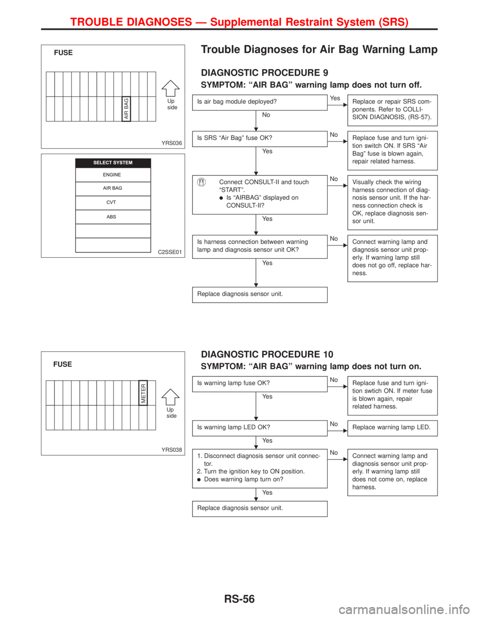
Trouble Diagnoses for Air Bag Warning Lamp
DIAGNOSTIC PROCEDURE 9
SYMPTOM: ªAIR BAGº warning lamp does not turn off.
Is air bag module deployed?
No
EYe s
Replace or repair SRS com-
ponents. Refer to COLLI-
SION DIAGNOSIS, (RS-57).
Is SRS ªAir Bagº fuse OK?
Ye s
ENo
Replace fuse and turn igni-
tion switch ON. If SRS ªAir
Bagº fuse is blown again,
repair related harness.
Connect CONSULT-II and touch
ªSTARTº.
lIs ªAIRBAGº displayed on
CONSULT-II?
Ye s
ENo
Visually check the wiring
harness connection of diag-
nosis sensor unit. If the har-
ness connection check is
OK, replace diagnosis sen-
sor unit.
Is harness connection between warning
lamp and diagnosis sensor unit OK?
Ye s
ENo
Connect warning lamp and
diagnosis sensor unit prop-
erly. If warning lamp still
does not go off, replace har-
ness.
Replace diagnosis sensor unit.
DIAGNOSTIC PROCEDURE 10
SYMPTOM: ªAIR BAGº warning lamp does not turn on.
Is warning lamp fuse OK?
Ye s
ENo
Replace fuse and turn igni-
tion swtich ON. If meter fuse
is blown again, repair
related harness.
Is warning lamp LED OK?
Ye s
ENo
Replace warning lamp LED.
1. Disconnect diagnosis sensor unit connec-
tor.
2. Turn the ignition key to ON position.
lDoes warning lamp turn on?
Ye s
ENo
Connect warning lamp and
diagnosis sensor unit prop-
erly. If warning lamp still
does not come on, replace
harness.
Replace diagnosis sensor unit.
YRS036
FUSE
Up
side
AIR BAG
C2SSE01
YRS038
FUSE
Up
side
METER
H
H
H
H
H
H
H
TROUBLE DIAGNOSES Ð Supplemental Restraint System (SRS)
RS-56
Page 2240 of 2267
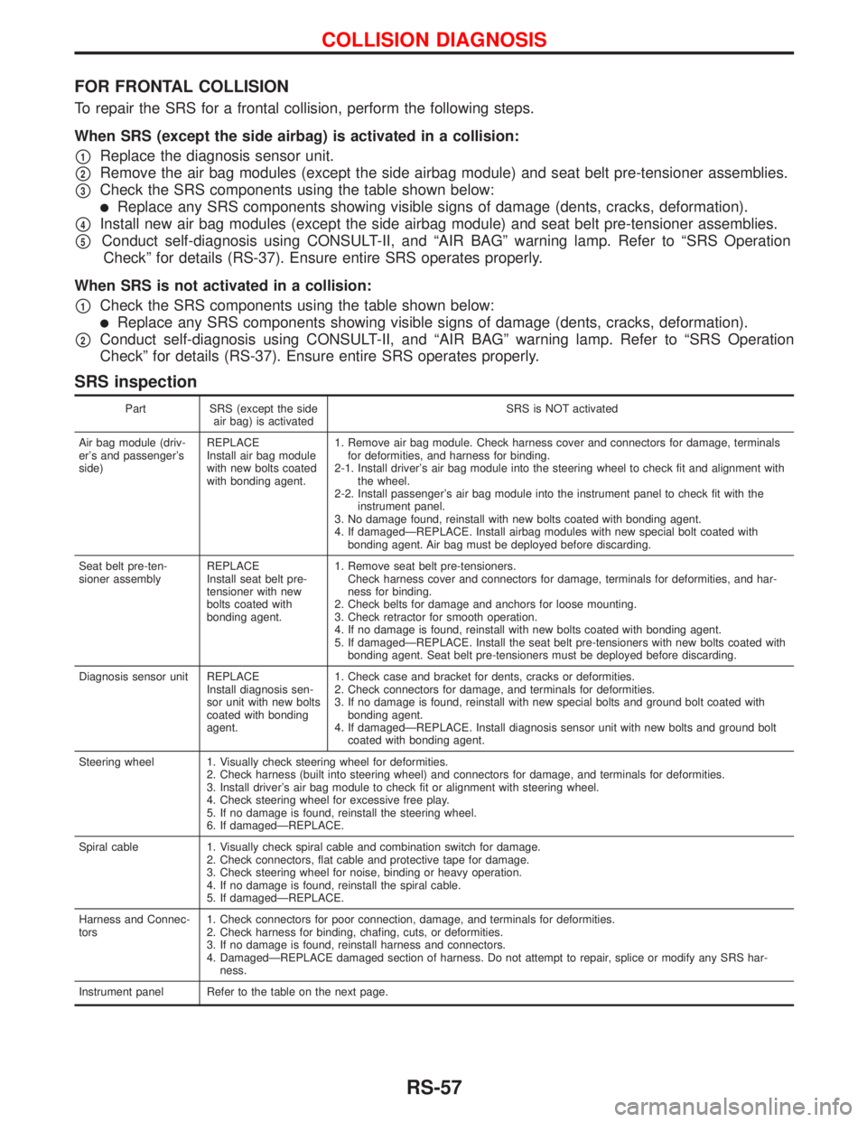
FOR FRONTAL COLLISION
To repair the SRS for a frontal collision, perform the following steps.
When SRS (except the side airbag) is activated in a collision:
p1Replace the diagnosis sensor unit.
p2Remove the air bag modules (except the side airbag module) and seat belt pre-tensioner assemblies.
p3Check the SRS components using the table shown below:
lReplace any SRS components showing visible signs of damage (dents, cracks, deformation).
p4Install new air bag modules (except the side airbag module) and seat belt pre-tensioner assemblies.
p5Conduct self-diagnosis using CONSULT-II, and ªAIR BAGº warning lamp. Refer to ªSRS Operation
Checkº for details (RS-37). Ensure entire SRS operates properly.
When SRS is not activated in a collision:
p1Check the SRS components using the table shown below:
lReplace any SRS components showing visible signs of damage (dents, cracks, deformation).
p2Conduct self-diagnosis using CONSULT-II, and ªAIR BAGº warning lamp. Refer to ªSRS Operation
Checkº for details (RS-37). Ensure entire SRS operates properly.
SRS inspection
Part SRS (except the side
air bag) is activatedSRS is NOT activated
Air bag module (driv-
er's and passenger's
side)REPLACE
Install air bag module
with new bolts coated
with bonding agent.1. Remove air bag module. Check harness cover and connectors for damage, terminals
for deformities, and harness for binding.
2-1. Install driver's air bag module into the steering wheel to check fit and alignment with
the wheel.
2-2. Install passenger's air bag module into the instrument panel to check fit with the
instrument panel.
3. No damage found, reinstall with new bolts coated with bonding agent.
4. If damagedÐREPLACE. Install airbag modules with new special bolt coated with
bonding agent. Air bag must be deployed before discarding.
Seat belt pre-ten-
sioner assemblyREPLACE
Install seat belt pre-
tensioner with new
bolts coated with
bonding agent.1. Remove seat belt pre-tensioners.
Check harness cover and connectors for damage, terminals for deformities, and har-
ness for binding.
2. Check belts for damage and anchors for loose mounting.
3. Check retractor for smooth operation.
4. If no damage is found, reinstall with new bolts coated with bonding agent.
5. If damagedÐREPLACE. Install the seat belt pre-tensioners with new bolts coated with
bonding agent. Seat belt pre-tensioners must be deployed before discarding.
Diagnosis sensor unit REPLACE
Install diagnosis sen-
sor unit with new bolts
coated with bonding
agent.1. Check case and bracket for dents, cracks or deformities.
2. Check connectors for damage, and terminals for deformities.
3. If no damage is found, reinstall with new special bolts and ground bolt coated with
bonding agent.
4. If damagedÐREPLACE. Install diagnosis sensor unit with new bolts and ground bolt
coated with bonding agent.
Steering wheel 1. Visually check steering wheel for deformities.
2. Check harness (built into steering wheel) and connectors for damage, and terminals for deformities.
3. Install driver's air bag module to check fit or alignment with steering wheel.
4. Check steering wheel for excessive free play.
5. If no damage is found, reinstall the steering wheel.
6. If damagedÐREPLACE.
Spiral cable 1. Visually check spiral cable and combination switch for damage.
2. Check connectors, flat cable and protective tape for damage.
3. Check steering wheel for noise, binding or heavy operation.
4. If no damage is found, reinstall the spiral cable.
5. If damagedÐREPLACE.
Harness and Connec-
tors1. Check connectors for poor connection, damage, and terminals for deformities.
2. Check harness for binding, chafing, cuts, or deformities.
3. If no damage is found, reinstall harness and connectors.
4. DamagedÐREPLACE damaged section of harness. Do not attempt to repair, splice or modify any SRS har-
ness.
Instrument panel Refer to the table on the next page.
COLLISION DIAGNOSIS
RS-57
Page 2252 of 2267
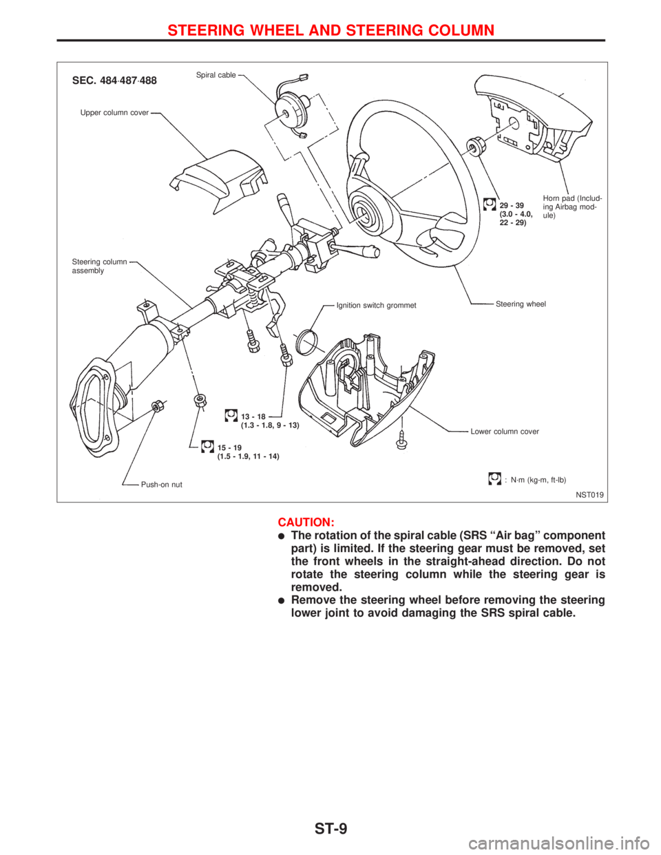
CAUTION:
lThe rotation of the spiral cable (SRS ªAir bagº component
part) is limited. If the steering gear must be removed, set
the front wheels in the straight-ahead direction. Do not
rotate the steering column while the steering gear is
removed.
lRemove the steering wheel before removing the steering
lower joint to avoid damaging the SRS spiral cable.
NST019 Upper column cover
Steering column
assembly
Ignition switch grommet
Lower column cover
13-18
(1.3 - 1.8, 9 - 13)
15-19
(1.5 - 1.9, 11 - 14)
Push-on nut
: N´m (kg-m, ft-lb)
SEC. 484×487×488Spiral cable
Steering wheel
29-39
(3.0 - 4.0,
22 - 29)Horn pad (Includ-
ing Airbag mod-
ule)
STEERING WHEEL AND STEERING COLUMN
ST-9