1999 NISSAN PRIMERA change key battery
[x] Cancel search: change key batteryPage 44 of 2267
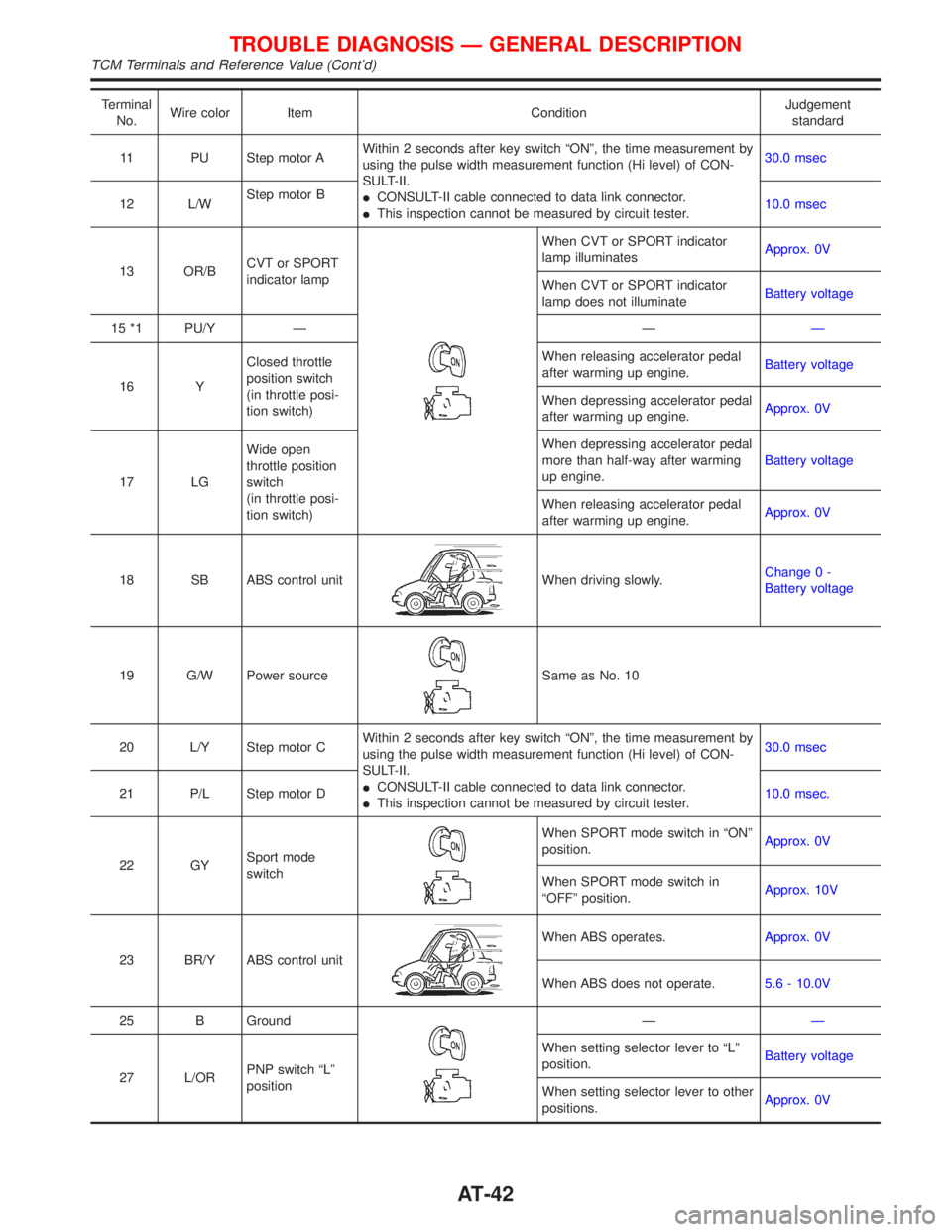
Terminal
No.Wire color Item ConditionJudgement
standard
11 PU Step motor AWithin 2 seconds after key switch ªONº, the time measurement by
using the pulse width measurement function (Hi level) of CON-
SULT-II.
ICONSULT-II cable connected to data link connector.
IThis inspection cannot be measured by circuit tester.30.0 msec
12 L/WStep motor B
10.0 msec
13 OR/BCVT or SPORT
indicator lamp
When CVT or SPORT indicator
lamp illuminatesApprox. 0V
When CVT or SPORT indicator
lamp does not illuminateBattery voltage
15 *1 PU/Y Ð ÐÐ
16 YClosed throttle
position switch
(in throttle posi-
tion switch)When releasing accelerator pedal
after warming up engine.Battery voltage
When depressing accelerator pedal
after warming up engine.Approx. 0V
17 LGWide open
throttle position
switch
(in throttle posi-
tion switch)When depressing accelerator pedal
more than half-way after warming
up engine.Battery voltage
When releasing accelerator pedal
after warming up engine.Approx. 0V
18 SB ABS control unit
When driving slowly.Change 0 -
Battery voltage
19 G/W Power source
Same as No. 10
20 L/Y Step motor CWithin 2 seconds after key switch ªONº, the time measurement by
using the pulse width measurement function (Hi level) of CON-
SULT-II.
ICONSULT-II cable connected to data link connector.
IThis inspection cannot be measured by circuit tester.30.0 msec
21 P/L Step motor D10.0 msec.
22 GYSport mode
switch
When SPORT mode switch in ªONº
position.Approx. 0V
When SPORT mode switch in
ªOFFº position.Approx. 10V
23 BR/Y ABS control unit
When ABS operates.Approx. 0V
When ABS does not operate.5.6 - 10.0V
25 B Ground
ÐÐ
27 L/ORPNP switch ªLº
positionWhen setting selector lever to ªLº
position.Battery voltage
When setting selector lever to other
positions.Approx. 0V
TROUBLE DIAGNOSIS Ð GENERAL DESCRIPTION
TCM Terminals and Reference Value (Cont'd)
AT-42
Page 487 of 2267
2. Select Mode 4 with GST (Generic Scan Tool).
The emission-related diagnostic information can be erased by selecting Mode 4 with GST (Generic Scan Tool).
How to Erase DTC (No Tools)NCEC0031S06031. If the ignition switch stays ªONº after repair work, be sure to turn ignition switch ªOFFº once. Wait at least
9 seconds and then turn it ªONº again.
2. Change the diagnostic test mode from Mode II to Mode I by using the data link connector. (See EC-QG-
48.)
The emission-related diagnostic information can be erased by changing the diagnostic test mode from Diag-
nostic Test Mode II to Mode I by using the data link connector. (Refer to EC-QG-48.)
NOTE:
IIf the battery is disconnected, the emission-related diagnostic information will be lost after approx.
24 hours.
IErasing the emission-related diagnostic information using CONSULT-II or GST is easier and
quicker than switching the mode using the data link connector.
IThe following data are cleared when the ECM memory is erased.
1) Diagnostic trouble codes
2) 1st trip diagnostic trouble codes
3) Freeze frame data
4) 1st trip freeze frame data
5) System readiness test (SRT) codes
6) Test values
7) Distance traveled while MI is activated
8) Others
Actual work procedures are explained using a DTC as an example. Be careful so that not only the DTC, but
all of the data listed above, are cleared from the ECM memory during work procedures.
Malfunction Indicator (MI)
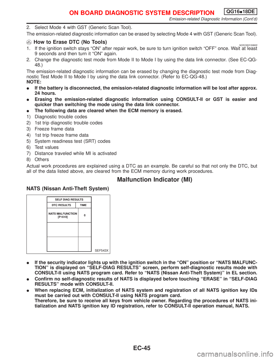
NATS (Nissan Anti-Theft System)
IIf the security indicator lights up with the ignition switch in the ªONº position or ªNATS MALFUNC-
TIONº is displayed on ªSELF-DIAG RESULTSº screen, perform self-diagnostic results mode with
CONSULT-II using NATS program card. Refer to ªNATS (Nissan Anti-Theft System)º in EL section.
IConfirm no self-diagnostic results of NATS is displayed before touching ªERASEº in ªSELF-DIAG
RESULTSº mode with CONSULT-II.
IWhen replacing ECM, initialization of NATS system and registration of all NATS ignition key IDs
must be carried out with CONSULT-II using NATS program card.
Therefore, be sure to receive all keys from vehicle owner. Regarding the procedures of NATS ini-
tialization and NATS ignition key ID registration, refer to CONSULT-II operation manual, NATS.
SEF543X
ON BOARD DIAGNOSTIC SYSTEM DESCRIPTIONQG16I18DE
Emission-related Diagnostic Information (Cont'd)
EC-45
Page 858 of 2267
How to Erase DTC (No Tools)NCEC0031S0603NOTE:
If the diagnostic trouble code is not for CVT related items (see EC-SR-6), skip step 2.
1. If the ignition switch stays ªONº after repair work, be sure to turn ignition switch ªOFFº once. Wait at least
9 seconds and then turn it ªONº again.
2. Perform ªSELF-DIAGNOSTIC PROCEDURE (Without CONSULT-II)º in AT section titled ªTROUBLE
DIAGNOSISº, ªSelf-diagnosisº. (The engine warm-up step can be skipped when performing the diagnosis
only to erase the DTC.)
3. Change the diagnostic test mode from Mode II to Mode I by using the data link connector. (See EC-SR-
61.)
The emission-related diagnostic information can be erased by changing the diagnostic test mode from Diag-
nostic Test Mode II to Mode I by using the data link connector. (Refer to EC-SR-61.)
NOTE:
IIf the battery is disconnected, the emission-related diagnostic information will be lost after approx.
24 hours.
IErasing the emission-related diagnostic information using CONSULT-II or GST is easier and
quicker than switching the mode using the data link connector.
IThe following data are cleared when the ECM memory is erased.
1) Diagnostic trouble codes
2) 1st trip diagnostic trouble codes
3) Freeze frame data
4) 1st trip freeze frame data
5) System readiness test (SRT) codes
6) Test values
7) Distance traveled while MI is activated
8) Others
Actual work procedures are explained using a DTC as an example. Be careful so that not only the DTC, but
all of the data listed above, are cleared from the ECM memory during work procedures.
Malfunction Indicator (MI)
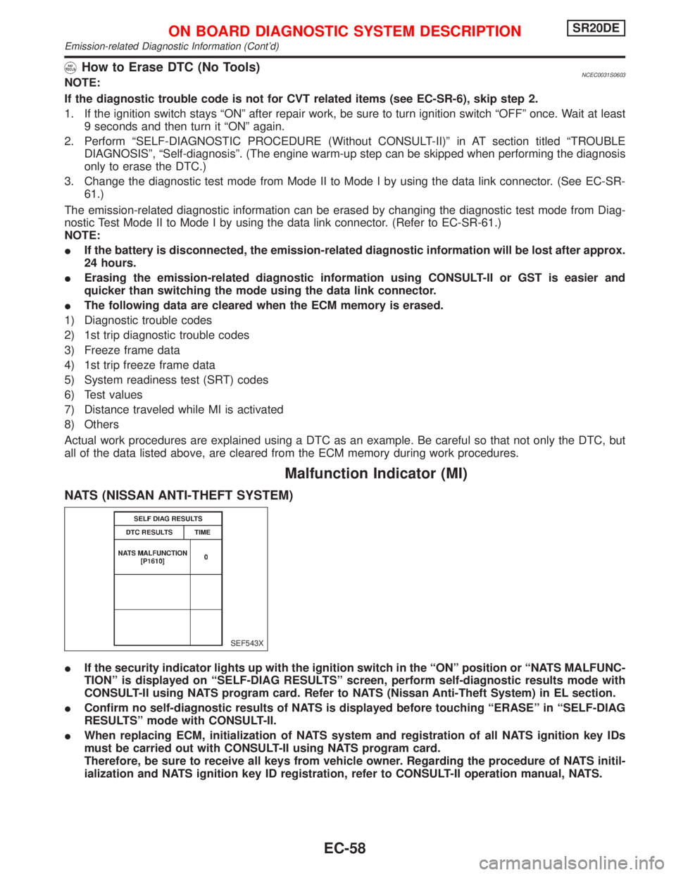
NATS (NISSAN ANTI-THEFT SYSTEM)
IIf the security indicator lights up with the ignition switch in the ªONº position or ªNATS MALFUNC-
TIONº is displayed on ªSELF-DIAG RESULTSº screen, perform self-diagnostic results mode with
CONSULT-II using NATS program card. Refer to NATS (Nissan Anti-Theft System) in EL section.
IConfirm no self-diagnostic results of NATS is displayed before touching ªERASEº in ªSELF-DIAG
RESULTSº mode with CONSULT-II.
IWhen replacing ECM, initialization of NATS system and registration of all NATS ignition key IDs
must be carried out with CONSULT-II using NATS program card.
Therefore, be sure to receive all keys from vehicle owner. Regarding the procedure of NATS initil-
ialization and NATS ignition key ID registration, refer to CONSULT-II operation manual, NATS.
SEF543X
ON BOARD DIAGNOSTIC SYSTEM DESCRIPTIONSR20DE
Emission-related Diagnostic Information (Cont'd)
EC-58
Page 1826 of 2267
Voltage check method
1. Remove the blown fuse and disconnect all loads (i.e. SW1 open, relay disconnected and solenoid dis-
connected) powered through the fuse.
2. Turn the ignition key to the ON or START position. Verify battery voltage at the B
+side of the fuse ter-
minal (one lead on the B
+terminal side of the fuse block and one lead on a known good ground).
3. With SW1 open and the DMM leads across both fuse terminals, check for voltage.
voltage; short is between fuse block and SW1 (point A).
no voltage; short is further down the circuit than SW1.
4. With SW1 closed, relay and solenoid disconnected and the DMM leads across both fuse terminals, check
for voltage.
voltage; short is between SW1 and the relay (point B).
no voltage; short is further down the circuit than the relay.
5. With SW1 closed, relay contacts jumped with fused jumper wire check for voltage.
voltage; short is down the circuit of the relay or between the relay and the disconnected solenoid
(point C).
no voltage; retrace steps and check power to fuse block.
GROUND INSPECTION
Ground connections are very important to the proper operation of electrical and electronic circuits. Ground
connections are often exposed to moisture, dirt and other corrosive elements. The corrosion (rust) can
become an unwanted resistance. This unwanted resistance can change the way a circuit works.
Electronically controlled circuits are very sensitive to proper grounding. A loose or corroded ground can
drastically affect an electronically controlled circuit. A poor or corroded ground can easily affect the circuit.
Even when the ground connection looks clean, there can be a thin film of rust on the surface.
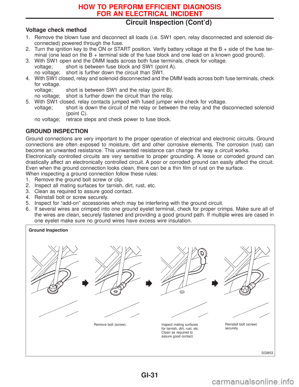
When inspecting a ground connection follow these rules:
1. Remove the ground bolt screw or clip.
2. Inspect all mating surfaces for tarnish, dirt, rust, etc.
3. Clean as required to assure good contact.
4. Reinstall bolt or screw securely.
5. Inspect for ªadd-onº accessories which may be interfering with the ground circuit.
6. If several wires are crimped into one ground eyelet terminal, check for proper crimps. Make sure all of
the wires are clean, securely fastened and providing a good ground path. If multiple wires are cased in
one eyelet make sure no ground wires have excess wire insulation.
SGI853
Ground Inspection
Remove bolt (screw). Inspect mating surfaces
for tarnish, dirt, rust, etc.
Clean as required to
assure good contact.Reinstall bolt (screw)
securely.
HOW TO PERFORM EFFICIENT DIAGNOSIS
FOR AN ELECTRICAL INCIDENT
Circuit Inspection (Cont'd)
GI-31