1999 NISSAN PRIMERA diagram
[x] Cancel search: diagramPage 3 of 2267
AUTOMATIC TRANSAXLE
SECTION
AT(H×CVT)
CONTENTS
TROUBLE DIAGNOSIS - INDEX....................................3
Alphabetical & P No. Index for DTC ...........................3
PRECAUTIONS...............................................................5
Precautions for Supplemental Restraint System
(SRS)²AIR BAG²and²SEAT BELT
PRE-TENSIONER²......................................................5
Precautions for On Board Diagnostic (OBD)
System of CVT and Engine .........................................5
Precautions ..................................................................5
Service Notice or Precautions .....................................6
Wiring Diagrams and Trouble Diagnosis .....................7
PREPARATION...............................................................8
Special Service Tools ..................................................8
OVERALL SYSTEM........................................................9
CVT Electrical Parts Location......................................9
Circuit Diagram ..........................................................10
Cross-sectional View - RE0F06A .............................. 11
Control System ..........................................................12
ON BOARD DIAGNOSTIC SYSTEM
DESCRIPTION...............................................................15
Introduction ................................................................15
OBD Function for CVT System .................................15
OBD Diagnostic Trouble Code (DTC) .......................15
Malfunction Indicator (MI) ..........................................18
CONSULT-II ...............................................................18
TROUBLE DIAGNOSIS - INTRODUCTION..................29
Introduction ................................................................29
Work Flow ..................................................................32
TROUBLE DIAGNOSIS - BASIC INSPECTION...........34
CVT Fluid Check .......................................................34
Stall Test ....................................................................34
Line Pressure Test .....................................................35
Road Test...................................................................36
TROUBLE DIAGNOSIS - GENERAL
DESCRIPTION...............................................................41
TCM Terminals and Reference Value........................41TROUBLE DIAGNOSIS FOR POWER SUPPLY..........45
Wiring Diagram - CVT - MAIN...................................45
DTC P0705 PARK/NEUTRAL POSITION (PNP)
SWITCH.........................................................................48
Description .................................................................48
Wiring Diagram - AT - PNP/SW.................................50
Diagnostic Procedure ................................................51
Component Inspection ...............................................53
DTC P0710 CVT FLUID TEMPERATURE SENSOR
CIRCUIT.........................................................................54
Description .................................................................54
Wiring Diagram - AT - FTS ........................................56
Diagnostic Procedure ................................................57
DTC P0715 PRIMARY SPEED SENSOR.....................59
Description .................................................................59
Wiring Diagram - AT - VSSA/T ..................................60
Diagnostic Procedure ................................................61
Component Inspection ...............................................61
DTC P0720 VEHICLE SPEED SENSOR CVT
(SECONDARY SPEED SENSOR)................................62
Description .................................................................62
Wiring Diagram - AT - VSSA/T ..................................64
Diagnostic Procedure ................................................65
Component Inspection ...............................................65
DTC P0725 ENGINE SPEED SIGNAL.........................66
Description .................................................................66
Wiring Diagram - AT - ENGSS ..................................67
Diagnostic Procedure ................................................68
DTC P0740 TORQUE CONVERTER CLUTCH
SOLENOID VALVE........................................................69
Description .................................................................69
Wiring Diagram - AT - TCV........................................71
Diagnostic Procedure ................................................72
Component Inspection ...............................................73
DTC P0745 LINE PRESSURE SOLENOID VALVE.....74
Description .................................................................74
AT
Page 4 of 2267
Wiring Diagram - AT - LPSV......................................76
Diagnostic Procedure ................................................77
Component Inspection ...............................................78
DTC P1705 THROTTLE POSITION SENSOR.............79
Description .................................................................79
Wiring Diagram - AT - TPS ........................................81
Diagnostic Procedure ................................................82
Component Inspection ...............................................85
DTC P1777 STEP MOTOR - CIRCUIT.........................86
Description .................................................................86
Wiring Diagram - AT - STM .......................................88
Diagnostic Procedure ................................................89
Component Inspection ...............................................90
DTC P1778 STEP MOTOR - FUNCTION.....................91
Description .................................................................91
Diagnostic Procedure ................................................93
DTC P1791 CVT FLUID PRESSURE SENSOR...........94
Description .................................................................94
Wiring Diagram - AT - FPS ........................................96
Diagnostic Procedure ................................................97
Component Inspection ...............................................98
CVT SAFE FUNCTION..................................................99
Description .................................................................99
Diagnostic Procedure ..............................................100
CONTROL UNIT (RAM), CONTROL UNIT (ROM).....101
Description ...............................................................101Diagnostic Procedure ..............................................102
CONTROL UNIT (EEPROM).......................................103
Description ...............................................................103
Diagnostic Procedure ..............................................104
TROUBLE DIAGNOSES FOR NON-DETECTABLE
ITEMS...........................................................................105
PNP Switch, Stop Lamp Switch and Throttle
Position Switch ........................................................105
Wiring Diagram - AT - NONDTC ............................. 110
ON-VEHICLE SERVICE.............................................. 114
Control Cable Adjustment ........................................ 114
Park/Neutral Position (PNP) Switch Adjustment ..... 114
Differential Side Oil Seal Replacement ................... 114
REMOVAL AND INSTALLATION............................... 116
Removal ................................................................... 116
Inspection................................................................. 116
Installation ................................................................ 117
Air Breather Hose .................................................... 118
CVT Fluid Cooler (Hyper CVT-M6) ......................... 118
Components............................................................. 119
SERVICE DATA AND SPECIFICATIONS (SDS).......120
General Specifications .............................................120
Stall Revolution ........................................................120
Line Pressure...........................................................120
Removal and Installation .........................................120
CONTENTS(Cont'd)
AT-2
Page 9 of 2267
The blinking of the CVT or SPORT indicator lamp for about 8 seconds will appear only once and be cleared.
The customer may resume normal driving conditions.
Always follow the ªWORK FLOWº (Refer to AT-32).
The SELF-DIAGNOSIS results will be as follows:
The first SELF-DIAGNOSIS will indicate damage to the vehicle speed sensor or the revolution sensor.
During the next SELF-DIAGNOSIS, performed after checking the sensor, no damages will be indicated.
OBD SELF-DIAGNOSISNCAT0004S04ICVT self-diagnosis is performed by the TCM in combination with the ECM. The results can be read through
the blinking pattern of the CVT or SPORT indicator. Refer to the table on AT-19 for the indicator used to
display each self-diagnostic result.
IThe self-diagnostic results indicated by the MI are automatically stored in both the ECM and TCM memo-
ries.
Always perform the procedure ªHOW TO ERASE DTCº on AT-16 to complete the repair and avoid
unnecessary blinking of the MI.
For details of OBD, refer to EC section (ªON BOARD DIAGNOSTIC SYSTEM DESCRIPTIONº).
ICertain systems and components, especially those related to OBD, may use a new style slide-
locking type harness connector.
For description and how to disconnect, refer to EL section, ªDescriptionº, ªHARNESS CONNEC-
TORº.
Wiring Diagrams and Trouble DiagnosisNCAT0005When you read wiring diagrams, refer to the followings:
IªHOW TO READ WIRING DIAGRAMSº in GI section
IªPOWER SUPPLY ROUTINGº for power distribution circuit in EL section
When you perform trouble diagnosis, refer to the followings:
IªHOW TO FOLLOW TEST GROUP IN TROUBLE DIAGNOSISº in GI section
IªHOW TO PERFORM EFFICIENT DIAGNOSIS FOR AN ELECTRICAL INCIDENTº in GI section
PRECAUTIONS
Service Notice or Precautions (Cont'd)
AT-7
Page 12 of 2267
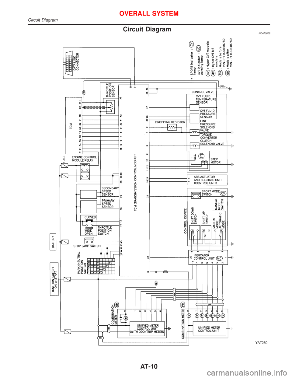
Circuit DiagramNCAT0009
YAT250
OVERALL SYSTEM
Circuit Diagram
AT-10
Page 47 of 2267
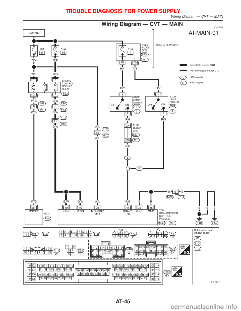
Wiring Diagram Ð CVT Ð MAINNCAT0031
YAT201
BATTERY
ENGINE
CONTROL
MODULE
RELAY
OFFONSTOP
LAMP
SWITCH
FUSE
BLOCK
(J/B)OFFONSTOP
LAMP
SWITCH: Detectable line for DTC
: Non-detectable line for DTC
: LHD models
: RHD models Refer to EL-POWER. FUSE
BLOCK
(J/B)
TCM
(TRANSMISSION
CONTROL
MODULE)
Refer to last page
(foldout page). ECM
TROUBLE DIAGNOSIS FOR POWER SUPPLY
Wiring Diagram Ð CVT Ð MAIN
AT-45
Page 48 of 2267
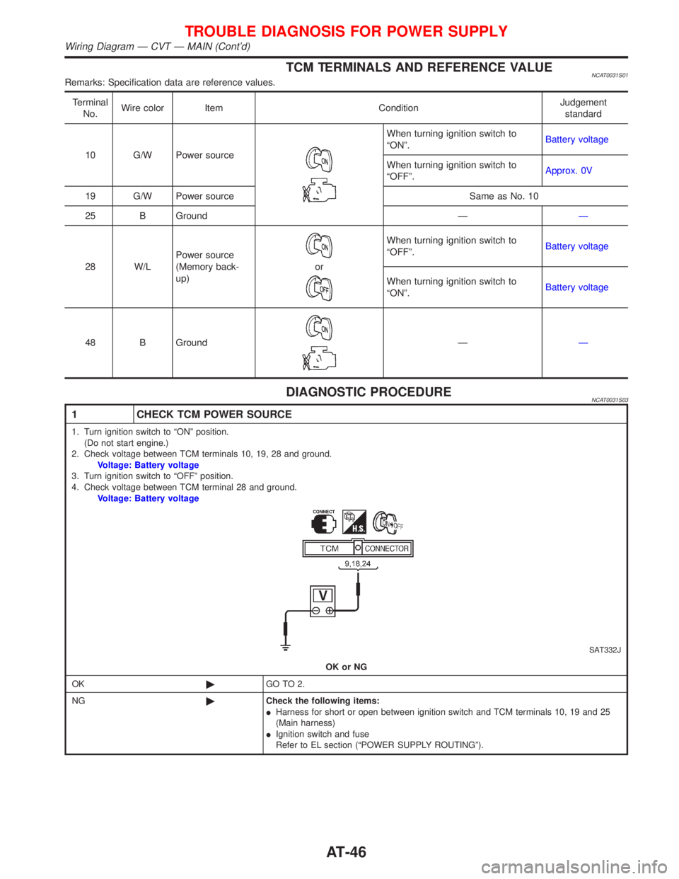
TCM TERMINALS AND REFERENCE VALUENCAT0031S01Remarks: Specification data are reference values.
Terminal
No.Wire color Item ConditionJudgement
standard
10 G/W Power source
When turning ignition switch to
ªONº.Battery voltage
When turning ignition switch to
ªOFFº.Approx. 0V
19 G/W Power source Same as No. 10
25 B Ground ÐÐ
28 W/LPower source
(Memory back-
up)
or
When turning ignition switch to
ªOFFº.Battery voltage
When turning ignition switch to
ªONº.Battery voltage
48 B Ground
ÐÐ
DIAGNOSTIC PROCEDURENCAT0031S03
1 CHECK TCM POWER SOURCE
1. Turn ignition switch to ªONº position.
(Do not start engine.)
2. Check voltage between TCM terminals 10, 19, 28 and ground.
Voltage: Battery voltage
3. Turn ignition switch to ªOFFº position.
4. Check voltage between TCM terminal 28 and ground.
Voltage: Battery voltage
SAT332J
OK or NG
OK©GO TO 2.
NG©Check the following items:
IHarness for short or open between ignition switch and TCM terminals 10, 19 and 25
(Main harness)
IIgnition switch and fuse
Refer to EL section (ªPOWER SUPPLY ROUTINGº).
TROUBLE DIAGNOSIS FOR POWER SUPPLY
Wiring Diagram Ð CVT Ð MAIN (Cont'd)
AT-46
Page 49 of 2267
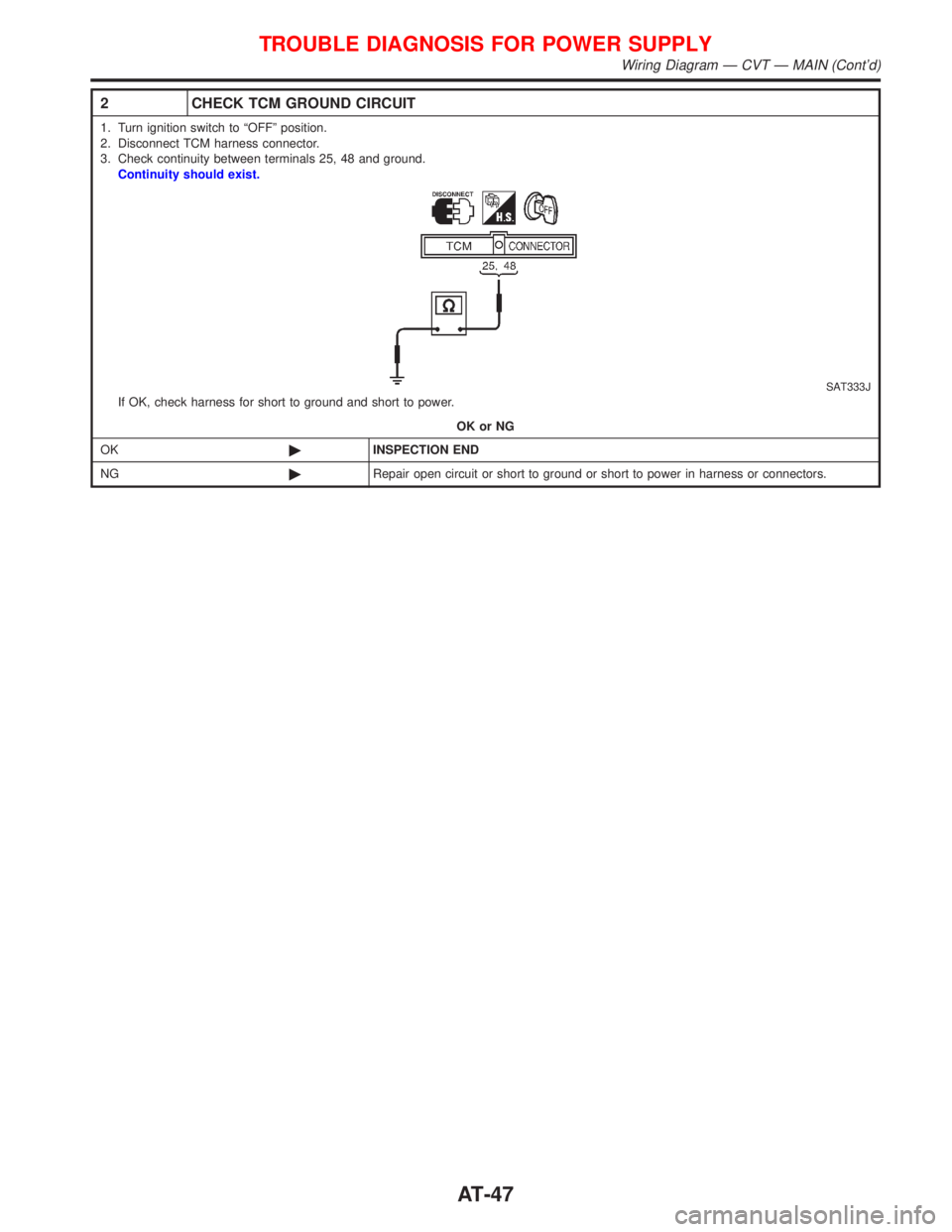
2 CHECK TCM GROUND CIRCUIT
1. Turn ignition switch to ªOFFº position.
2. Disconnect TCM harness connector.
3. Check continuity between terminals 25, 48 and ground.
Continuity should exist.
SAT333JIf OK, check harness for short to ground and short to power.
OK or NG
OK©INSPECTION END
NG©Repair open circuit or short to ground or short to power in harness or connectors.
TROUBLE DIAGNOSIS FOR POWER SUPPLY
Wiring Diagram Ð CVT Ð MAIN (Cont'd)
AT-47
Page 52 of 2267
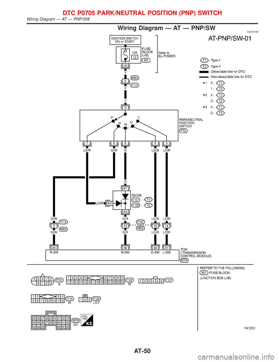
Wiring Diagram Ð AT Ð PNP/SWNCAT0199
YAT251
DTC P0705 PARK/NEUTRAL POSITION (PNP) SWITCH
Wiring Diagram Ð AT Ð PNP/SW
AT-50