Page 126 of 2267

Precautions When Working On ABS
lUse recommended tyres in combination with ABS.
lInstall tyres or studded tyres, etc. with the same size.
lIf different sizes of tyres, or tyres other than the ones
recommended for use with the ABS, are fitted, stopping
distance will increase and control and stability could
deteriorate.
lWhen changing brake pads, use Nissan genuine parts.
lWhen fitting radios etc, do not position the radio unit,
antenna, or antenna cables within an area of about 100
mm (3.94 in) of the control unit.
lWhen doing any work that requires electro-welding, first
remove the control unit.
lMake sure when taking a power supply for the audio,
lamps etc., not to take this from any ABS-related har-
ness. (Refer to the electrical wiring diagrams for ABS-
related harnesses)
Wiring Diagrams and Trouble Diagnosis
When you read wiring diagrams, refer to the following:
lGI-11, ªHOW TO READ WIRING DIAGRAMSº
lEL-10, ªPOWER SUPPLY ROUTINGº
When you perform trouble diagnosis, refer to the following:
lGI-35, ªHOW TO FOLLOW TEST GROUPS IN TROUBLE DIAGNOSISº
lGI-24, ªHOW TO PERFORM EFFICIENT DIAGNOSES FOR AN ELECTRICAL INCIDENTº
PRECAUTIONS
BR-4
Page 183 of 2267
Circuit Diagram for Quick Pinpoint Check
YBR228
TROUBLE DIAGNOSES
BR-61
Page 184 of 2267
Wiring Diagram Ð ABS Ð
MODELS WITH SELF-DIAGNOSIS FUNCTION
YBR208 BATTERYIGNITION SWITCH
ON or START
FUSE
BLOCK
(J/B)Refer to EL-POWER.
: LHD models
: RHD models: CVT models
: M/T models
RELEASEDDEPRESSEDSTOP LAMP
SWITCH
FUSE
BLOCK
(J/B)COMBINATION METER
(ABS WARNING LAMP)
ABS ACTUATOR
AND ELECTRIC
UNIT
(CONTROL UNIT)
TCM
(TRANSMISSION CON-
TROL MODULE)DATA LINK CON-
NECTOR
Refer to las page (Foldout page).
TROUBLE DIAGNOSES
BR-62
Page 185 of 2267
MODELS WITHOUT SELF-DIAGNOSIS FUNCTION
YBR229
TROUBLE DIAGNOSES
Wiring Diagram Ð ABS Ð (Cont'd)
BR-63
Page 186 of 2267
YBR230
TROUBLE DIAGNOSES
Wiring Diagram Ð ABS Ð (Cont'd)
BR-64
Page 187 of 2267
YBR231
TROUBLE DIAGNOSES
Wiring Diagram Ð ABS Ð (Cont'd)
BR-65
Page 188 of 2267
YBR232
TROUBLE DIAGNOSES
Wiring Diagram Ð ABS Ð (Cont'd)
BR-66
Page 209 of 2267

Diagnostic Procedure 9 (ABS does not
work.)
CHECK WARNING LAMP ACTIVATE.
Does the ABS warning lamp activate?
No
EYe s
Carry out self-diagnosis.
Refer to BR-67.
Go toin Diagnostic Procedure 7,
BR-86.
Note: ABS does not work when vehicle speed is under 10
km/h (6 MPH).
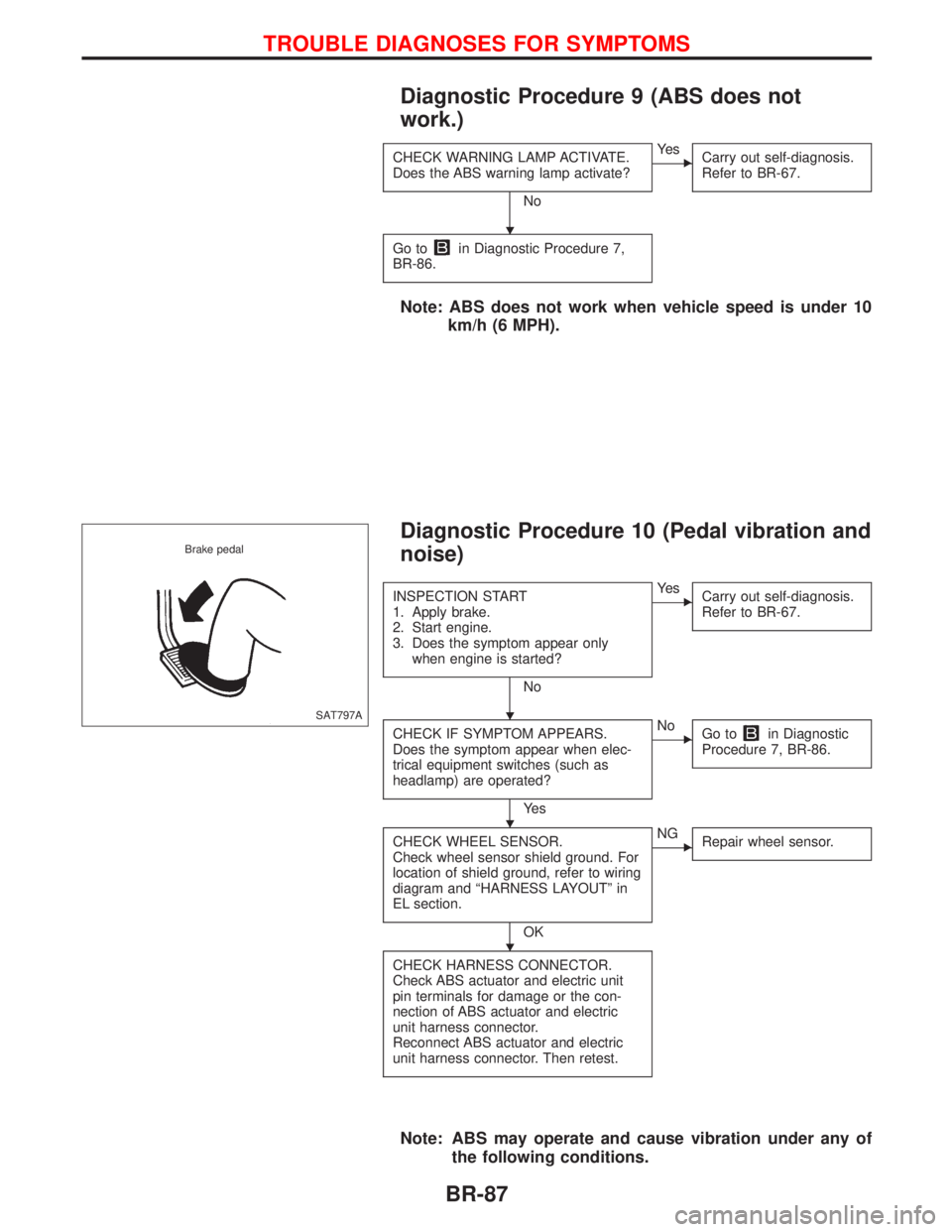
Diagnostic Procedure 10 (Pedal vibration and
noise)
INSPECTION START
1. Apply brake.
2. Start engine.
3. Does the symptom appear only
when engine is started?
No
EYe s
Carry out self-diagnosis.
Refer to BR-67.
CHECK IF SYMPTOM APPEARS.
Does the symptom appear when elec-
trical equipment switches (such as
headlamp) are operated?
Ye s
ENo
Go toin Diagnostic
Procedure 7, BR-86.
CHECK WHEEL SENSOR.
Check wheel sensor shield ground. For
location of shield ground, refer to wiring
diagram and ªHARNESS LAYOUTº in
EL section.
OK
ENG
Repair wheel sensor.
CHECK HARNESS CONNECTOR.
Check ABS actuator and electric unit
pin terminals for damage or the con-
nection of ABS actuator and electric
unit harness connector.
Reconnect ABS actuator and electric
unit harness connector. Then retest.
Note: ABS may operate and cause vibration under any of
the following conditions.
SAT797A Brake pedal
H
H
H
H
TROUBLE DIAGNOSES FOR SYMPTOMS
BR-87