Page 254 of 2267
lWhen removing or installing seats with side air bag module, be sure to disconnect or connect side air
bag sub harness connector.
lWhen removing or installing the seat trim, handle it carefully to keep dirt out and avoid damage.
HFor Wiring Diagram, refer to ªPOWER SEATº in EL section.
Front Seat
NBT048
18-24
(1.9 - 2.4, 14 - 17)
18-24
(1.9 - 2.4, 14 - 17)
18-24
(1.9 - 2.4, 14 - 17)
: N´m (kg-m, ft-lb)
21-26
(2.1 - 2.7, 15.5 - 19.2)
Manual seat
Side airbag sub
harness connector
SEAT
BT-40
Page 256 of 2267
Heated Seat
lWhen handling seat, be extremely careful not to scratch heating unit.
lTo replace heating unit, seat trim and pad should be separated.
lDo not use any organic solvent, such as thinner, benzene, alcohol, gasoline, etc. to clean trims.
Seatback heating unit removal & installation
HFor Wiring Diagram, refer to ªHEATED SEATº in EL section.
SBF424H Seatback trim
Heating
unit
Thermostat
Seat cushion trimTrim temperature
ÉC (ÉF)
Thermostat
operationIncreasing to
35-45
(95 - 113)
OFFDecreasing to
15-25
(59 - 77)
ON
SEAT
BT-42
Page 262 of 2267
HFor Wiring Diagram, refer to ªELECTRIC SUNROOFº in EL section.
NBT049
SEC. 736
Rear drain
assemblyRear drain screw
Link and wire
assembly
Guide stopper
Wind deflector mounting nuts
Drain hose
Sunroof unit bracket
5.1 - 6.4
(0.52 - 0.65,
45.1 - 56.4) Motor
switch bracketMotor assembly
5.1 - 6.4
(0.52 - 0.65,
45.1 - 56.4)Sunroof frame
assembly Wind
deflector
assemblyWind deflector mounting
screws
Shade assemblyGuide stopperScrew
: N´m (kg-m, in-lb) Lid assembly
Manual type
Drive
Handle
: Apply grease
SUNROOF
BT-48
Page 272 of 2267
Door Mirror
CAUTION:
Be careful not to scratch door rearview mirror body.
HFor Wiring Diagram, refer to ªPOWER DOOR MIRRORº in EL section.
REMOVAL Ð Door mirror
p1Remove door trim. Refer to ªDoor Trimº for details, BT-24.
p2Remove inner cover from front corner of door.
p3Disconnect door mirror harness connector.
p4Remove bolts securing door mirror, then remove door mirror assembly.
YBT036
SEC. 963
Pawl
Removal:
lWrap flat-blade of screwdriver with a cloth to prevent scratching.
Do not insert too far. Push mirror away from car to release.
Mirror
Cloth
Flat-bladed
screwdriverInside
Outside
MIRROR
BT-58
Page 295 of 2267

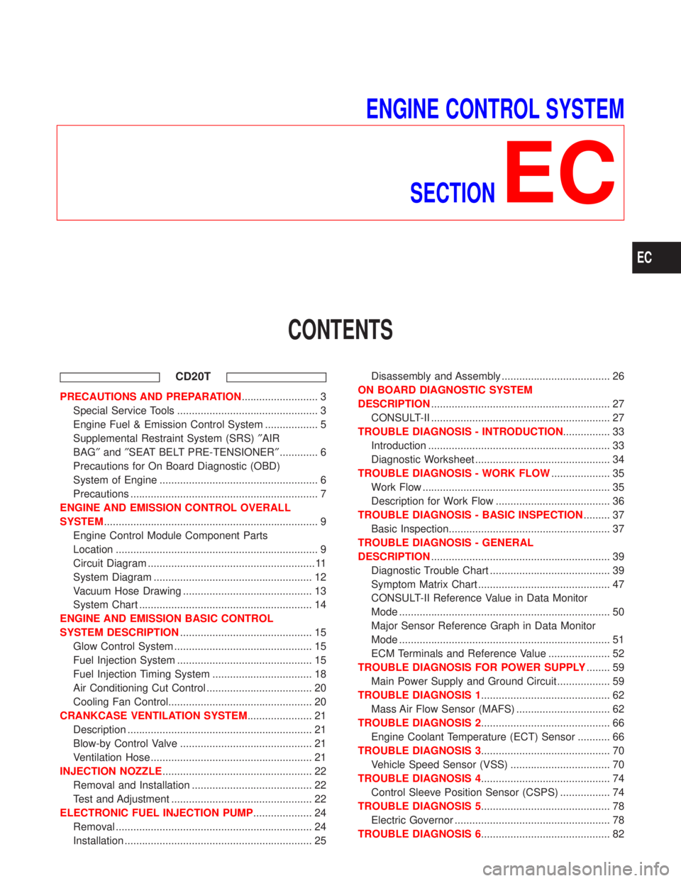
ENGINE CONTROL SYSTEM
SECTION
EC
CONTENTS
CD20T
PRECAUTIONS AND PREPARATION.......................... 3
Special Service Tools ................................................ 3
Engine Fuel & Emission Control System .................. 5
Supplemental Restraint System (SRS)²AIR
BAG²and²SEAT BELT PRE-TENSIONER²............. 6
Precautions for On Board Diagnostic (OBD)
System of Engine ...................................................... 6
Precautions ................................................................ 7
ENGINE AND EMISSION CONTROL OVERALL
SYSTEM......................................................................... 9
Engine Control Module Component Parts
Location ..................................................................... 9
Circuit Diagram ......................................................... 11
System Diagram ...................................................... 12
Vacuum Hose Drawing ............................................ 13
System Chart ........................................................... 14
ENGINE AND EMISSION BASIC CONTROL
SYSTEM DESCRIPTION............................................. 15
Glow Control System ............................................... 15
Fuel Injection System .............................................. 15
Fuel Injection Timing System .................................. 18
Air Conditioning Cut Control .................................... 20
Cooling Fan Control................................................. 20
CRANKCASE VENTILATION SYSTEM...................... 21
Description ............................................................... 21
Blow-by Control Valve ............................................. 21
Ventilation Hose ....................................................... 21
INJECTION NOZZLE................................................... 22
Removal and Installation ......................................... 22
Test and Adjustment ................................................ 22
ELECTRONIC FUEL INJECTION PUMP.................... 24
Removal ................................................................... 24
Installation ................................................................ 25Disassembly and Assembly ..................................... 26
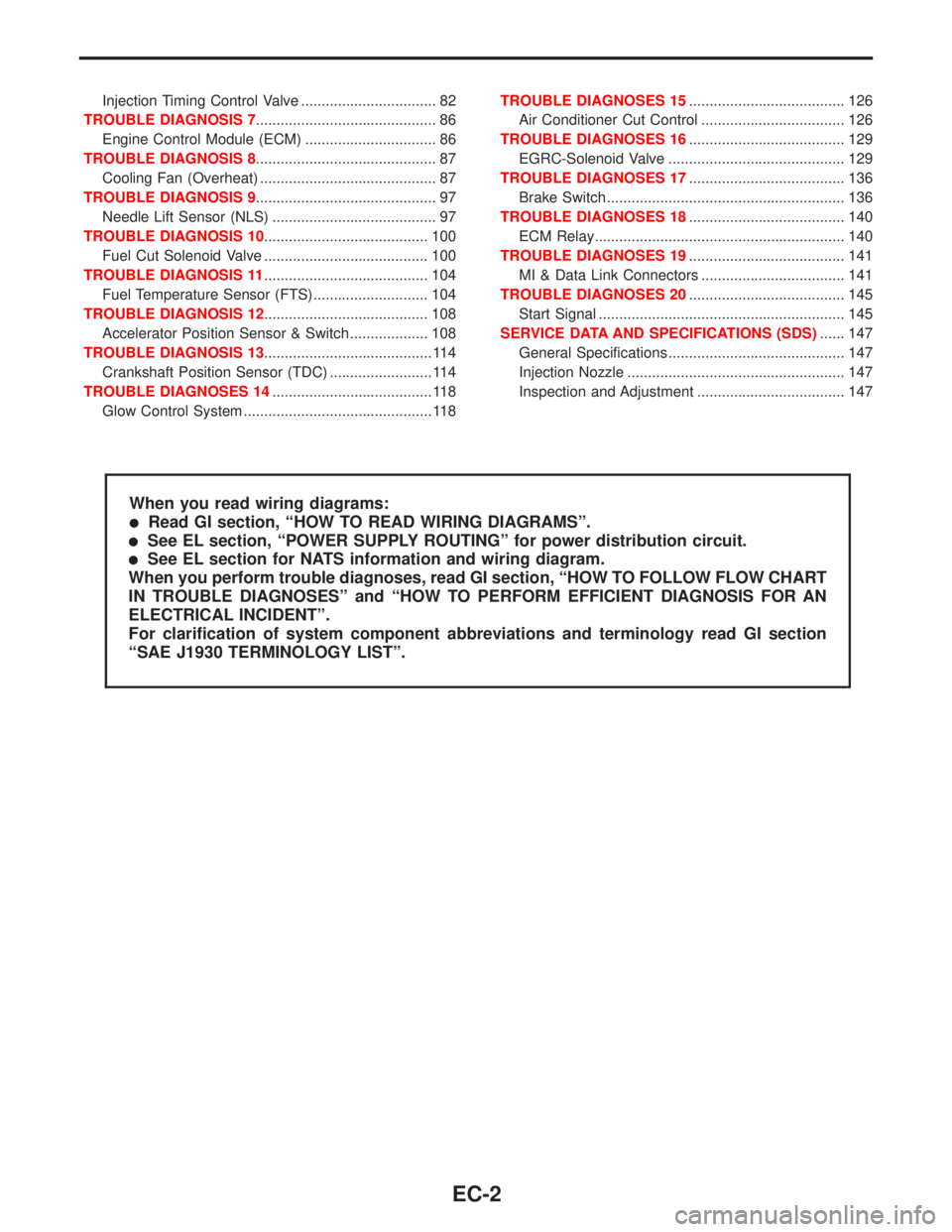
ON BOARD DIAGNOSTIC SYSTEM
DESCRIPTION............................................................. 27
CONSULT-II ............................................................. 27
TROUBLE DIAGNOSIS - INTRODUCTION................ 33
Introduction .............................................................. 33
Diagnostic Worksheet .............................................. 34
TROUBLE DIAGNOSIS - WORK FLOW.................... 35
Work Flow ................................................................ 35
Description for Work Flow ....................................... 36
TROUBLE DIAGNOSIS - BASIC INSPECTION......... 37
Basic Inspection....................................................... 37
TROUBLE DIAGNOSIS - GENERAL
DESCRIPTION............................................................. 39
Diagnostic Trouble Chart ......................................... 39
Symptom Matrix Chart ............................................. 47
CONSULT-II Reference Value in Data Monitor
Mode ........................................................................ 50
Major Sensor Reference Graph in Data Monitor
Mode ........................................................................ 51
ECM Terminals and Reference Value ..................... 52
TROUBLE DIAGNOSIS FOR POWER SUPPLY........ 59
Main Power Supply and Ground Circuit .................. 59
TROUBLE DIAGNOSIS 1............................................ 62
Mass Air Flow Sensor (MAFS) ................................ 62
TROUBLE DIAGNOSIS 2............................................ 66
Engine Coolant Temperature (ECT) Sensor ........... 66
TROUBLE DIAGNOSIS 3............................................ 70
Vehicle Speed Sensor (VSS) .................................. 70
TROUBLE DIAGNOSIS 4............................................ 74
Control Sleeve Position Sensor (CSPS) ................. 74
TROUBLE DIAGNOSIS 5............................................ 78
Electric Governor ..................................................... 78
TROUBLE DIAGNOSIS 6............................................ 82
EC
Page 296 of 2267

Injection Timing Control Valve ................................. 82
TROUBLE DIAGNOSIS 7............................................ 86
Engine Control Module (ECM) ................................ 86
TROUBLE DIAGNOSIS 8............................................ 87
Cooling Fan (Overheat) ........................................... 87
TROUBLE DIAGNOSIS 9............................................ 97
Needle Lift Sensor (NLS) ........................................ 97
TROUBLE DIAGNOSIS 10........................................ 100
Fuel Cut Solenoid Valve ........................................ 100
TROUBLE DIAGNOSIS 11........................................ 104
Fuel Temperature Sensor (FTS)............................ 104
TROUBLE DIAGNOSIS 12........................................ 108
Accelerator Position Sensor & Switch ................... 108
TROUBLE DIAGNOSIS 13......................................... 114
Crankshaft Position Sensor (TDC) ......................... 114
TROUBLE DIAGNOSES 14....................................... 118
Glow Control System .............................................. 118TROUBLE DIAGNOSES 15...................................... 126
Air Conditioner Cut Control ................................... 126
TROUBLE DIAGNOSES 16...................................... 129
EGRC-Solenoid Valve ........................................... 129
TROUBLE DIAGNOSES 17...................................... 136
Brake Switch .......................................................... 136
TROUBLE DIAGNOSES 18...................................... 140
ECM Relay............................................................. 140
TROUBLE DIAGNOSES 19...................................... 141
MI & Data Link Connectors ................................... 141
TROUBLE DIAGNOSES 20...................................... 145
Start Signal ............................................................ 145
SERVICE DATA AND SPECIFICATIONS (SDS)...... 147
General Specifications ........................................... 147
Injection Nozzle ..................................................... 147
Inspection and Adjustment .................................... 147
When you read wiring diagrams:
lRead GI section, ªHOW TO READ WIRING DIAGRAMSº.
lSee EL section, ªPOWER SUPPLY ROUTINGº for power distribution circuit.
lSee EL section for NATS information and wiring diagram.
When you perform trouble diagnoses, read GI section, ªHOW TO FOLLOW FLOW CHART
IN TROUBLE DIAGNOSESº and ªHOW TO PERFORM EFFICIENT DIAGNOSIS FOR AN
ELECTRICAL INCIDENTº.
For clarification of system component abbreviations and terminology read GI section
ªSAE J1930 TERMINOLOGY LISTº.
EC-2
Page 305 of 2267
Circuit Diagram
YEC099A
ENGINE AND EMISSION CONTROL OVERALL SYSTEMCD20T
EC-11
Page 306 of 2267
System Diagram
YEC125A
ENGINE AND EMISSION CONTROL OVERALL SYSTEMCD20T
EC-12