1999 NISSAN PRIMERA Fluids
[x] Cancel search: FluidsPage 122 of 2267
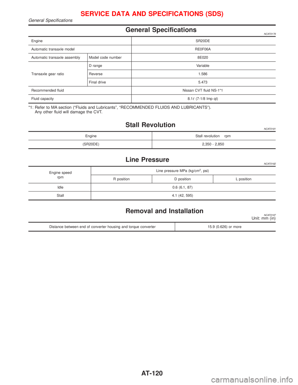
General SpecificationsNCAT0179
EngineSR20DE
Automatic transaxle modelRE0F06A
Automatic transaxle assembly Model code number 8E020
Transaxle gear ratioD range Variable
Reverse 1.586
Final drive 5.473
Recommended fluidNissan CVT fluid NS-1*1
Fluid capacity8.1(7-1/8 Imp qt)
*1: Refer to MA section (ªFluids and Lubricantsº, ªRECOMMENDED FLUIDS AND LUBRICANTSº).
Any other fluid will damage the CVT.
Stall RevolutionNCAT0181
Engine Stall revolution rpm
(SR20DE) 2,350 - 2,850
Line PressureNCAT0182
Engine speed
rpmLine pressure MPa (kg/cm2, psi)
R position D position L position
Idle 0.6 (6.1, 87)
Stall 4.1 (42, 595)
Removal and InstallationNCAT0197Unit: mm (in)
Distance between end of converter housing and torque converter 15.9 (0.626) or more
SERVICE DATA AND SPECIFICATIONS (SDS)
General Specifications
AT-120
Page 381 of 2267
Cooling Fan (Overheat)
SYSTEM DESCRIPTION
Vehicle speed sensorEVehicle speed
ECM
ECooling
fan
relay(s)Engine coolant temperature sensorEEngine coolant temperature
Air conditioner switch
EAir conditioner ªONº signal
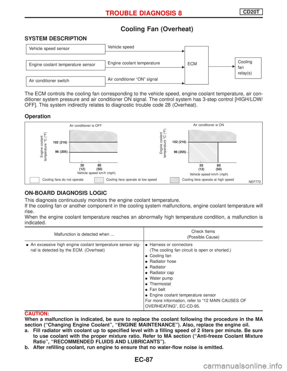
The ECM controls the cooling fan corresponding to the vehicle speed, engine coolant temperature, air con-
ditioner system pressure and air conditioner ON signal. The control system has 3-step control [HIGH/LOW/
OFF]. This system indirectly relates to diagnostic trouble code 28 (Overheat).
Operation
ON-BOARD DIAGNOSIS LOGIC
This diagnosis continuously monitors the engine coolant temperature.
If the cooling fan or another component in the cooling system malfunctions, engine coolant temperature will
rise.
When the engine coolant temperature reaches an abnormally high temperature condition, a malfunction is
indicated.
Malfunction is detected when ...Check Items
(Possible Cause)
lAn excessive high engine coolant temperature sensor sig-
nal is detected by the ECM. (Overheat)lHarness or connectors
(The cooling fan circuit is open or shorted.)
lCooling fan
lRadiator hose
lRadiator
lRadiator cap
lWater pump
lThermostat
lFan belt
lEngine coolant temperature sensor
For more information, refer to ª12 MAIN CAUSES OF
OVERHEATINGº, EC-CD-95.
CAUTION:
When a malfunction is indicated, be sure to replace the coolant following the procedure in the MA
section (ªChanging Engine Coolantº, ªENGINE MAINTENANCEº). Also, replace the engine oil.
a. Fill radiator with coolant up to specified level with a filling speed of 2 liters per minute. Be sure
to use coolant with the proper mixture ratio. Refer to MA section (ªAnti-freeze Coolant Mixture
Ratioº, ªRECOMMENDED FLUIDS AND LUBRICANTSº).
b. After refilling coolant, run engine to ensure that no water-flow noise is emitted.
NEF772
Engine coolant
temperature ÉC (ÉF)
Air conditioner is OFF
.102 (216)
.96 (205)
.20
(12).80
(50)
Vehicle speed km/h (mph)
Cooling fans do not operateCooling fans operate at high speed
Engine coolant
temperature ÉC (ÉF)
Vehicle speed km/h (mph)
.20
(12).80
(50)
.102 (216)
.96 (205)Air conditioner is ON
Cooling fans operate at low speed
TROUBLE DIAGNOSIS 8CD20T
EC-87
Page 389 of 2267
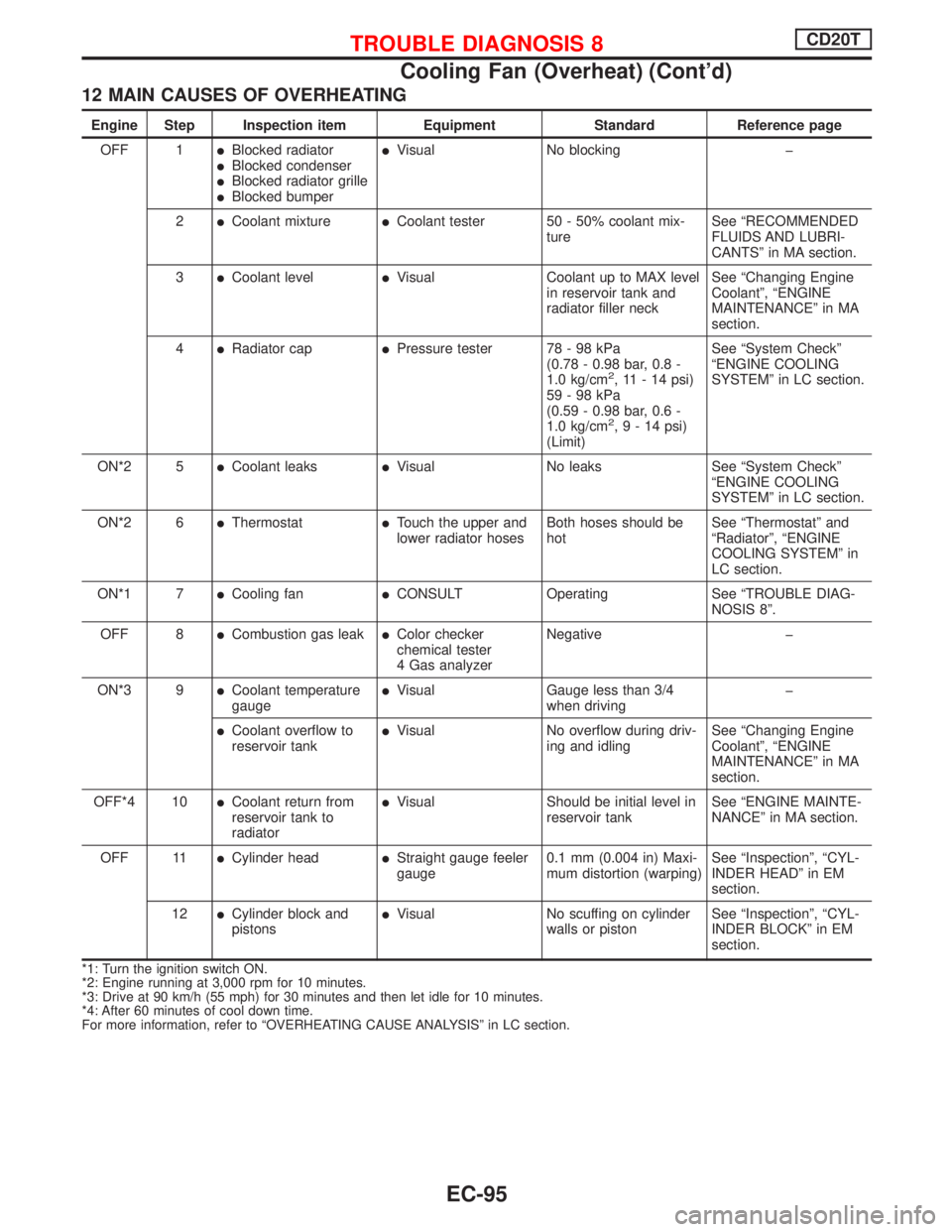
12 MAIN CAUSES OF OVERHEATING
Engine Step Inspection item Equipment Standard Reference page
OFF 1
lBlocked radiatorlBlocked condenserlBlocked radiator grillelBlocked bumper
lVisual No blocking þ
2
lCoolant mixturelCoolant tester 50 - 50% coolant mix-
tureSee ªRECOMMENDED
FLUIDS AND LUBRI-
CANTSº in MA section.
3
lCoolant levellVisual Coolant up to MAX level
in reservoir tank and
radiator filler neckSee ªChanging Engine
Coolantº, ªENGINE
MAINTENANCEº in MA
section.
4
lRadiator caplPressure tester 78 - 98 kPa
(0.78 - 0.98 bar, 0.8 -
1.0 kg/cm
2, 11 - 14 psi)
59-98kPa
(0.59 - 0.98 bar, 0.6 -
1.0 kg/cm
2,9-14psi)
(Limit)See ªSystem Checkº
ªENGINE COOLING
SYSTEMº in LC section.
ON*2 5
lCoolant leakslVisual No leaks See ªSystem Checkº
ªENGINE COOLING
SYSTEMº in LC section.
ON*2 6
lThermostatlTouch the upper and
lower radiator hosesBoth hoses should be
hotSee ªThermostatº and
ªRadiatorº, ªENGINE
COOLING SYSTEMº in
LC section.
ON*1 7
lCooling fanlCONSULT Operating See ªTROUBLE DIAG-
NOSIS 8º.
OFF 8
lCombustion gas leaklColor checker
chemical tester
4 Gas analyzerNegative þ
ON*3 9
lCoolant temperature
gaugelVisual Gauge less than 3/4
when drivingþ
lCoolant overflow to
reservoir tanklVisual No overflow during driv-
ing and idlingSee ªChanging Engine
Coolantº, ªENGINE
MAINTENANCEº in MA
section.
OFF*4 10
lCoolant return from
reservoir tank to
radiatorlVisual Should be initial level in
reservoir tankSee ªENGINE MAINTE-
NANCEº in MA section.
OFF 11
lCylinder headlStraight gauge feeler
gauge0.1 mm (0.004 in) Maxi-
mum distortion (warping)See ªInspectionº, ªCYL-
INDER HEADº in EM
section.
12
lCylinder block and
pistonslVisual No scuffing on cylinder
walls or pistonSee ªInspectionº, ªCYL-
INDER BLOCKº in EM
section.
*1: Turn the ignition switch ON.
*2: Engine running at 3,000 rpm for 10 minutes.
*3: Drive at 90 km/h (55 mph) for 30 minutes and then let idle for 10 minutes.
*4: After 60 minutes of cool down time.
For more information, refer to ªOVERHEATING CAUSE ANALYSISº in LC section.
TROUBLE DIAGNOSIS 8CD20T
Cooling Fan (Overheat) (Cont'd)
EC-95
Page 732 of 2267
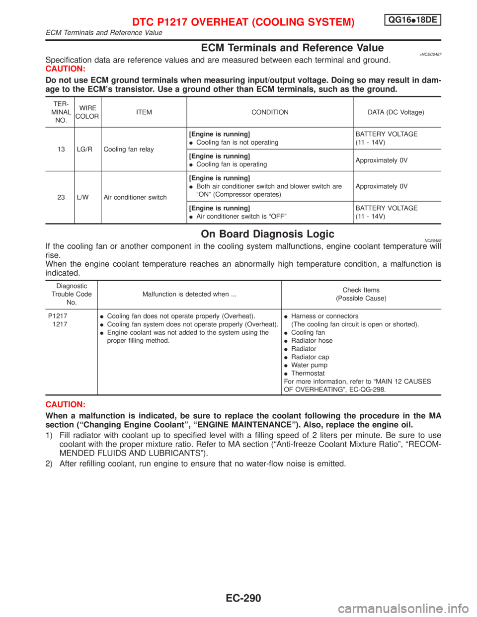
ECM Terminals and Reference Value=NCEC0487Specification data are reference values and are measured between each terminal and ground.
CAUTION:
Do not use ECM ground terminals when measuring input/output voltage. Doing so may result in dam-
age to the ECM's transistor. Use a ground other than ECM terminals, such as the ground.
TER-
MINAL
NO.WIRE
COLORITEM CONDITION DATA (DC Voltage)
13 LG/R Cooling fan relay[Engine is running]
ICooling fan is not operatingBATTERY VOLTAGE
(11 - 14V)
[Engine is running]
ICooling fan is operatingApproximately 0V
23 L/W Air conditioner switch[Engine is running]
IBoth air conditioner switch and blower switch are
ªONº (Compressor operates)Approximately 0V
[Engine is running]
IAir conditioner switch is ªOFFºBATTERY VOLTAGE
(11 - 14V)
On Board Diagnosis LogicNCE0488If the cooling fan or another component in the cooling system malfunctions, engine coolant temperature will
rise.
When the engine coolant temperature reaches an abnormally high temperature condition, a malfunction is
indicated.
Diagnostic
Trouble Code
No.Malfunction is detected when ...Check Items
(Possible Cause)
P1217
1217ICooling fan does not operate properly (Overheat).
ICooling fan system does not operate properly (Overheat).
IEngine coolant was not added to the system using the
proper filling method.IHarness or connectors
(The cooling fan circuit is open or shorted).
ICooling fan
IRadiator hose
IRadiator
IRadiator cap
IWater pump
IThermostat
For more information, refer to ªMAIN 12 CAUSES
OF OVERHEATINGº, EC-QG-298.
CAUTION:
When a malfunction is indicated, be sure to replace the coolant following the procedure in the MA
section (ªChanging Engine Coolantº, ªENGINE MAINTENANCEº). Also, replace the engine oil.
1) Fill radiator with coolant up to specified level with a filling speed of 2 liters per minute. Be sure to use
coolant with the proper mixture ratio. Refer to MA section (ªAnti-freeze Coolant Mixture Ratioº, ªRECOM-
MENDED FLUIDS AND LUBRICANTSº).
2) After refilling coolant, run engine to ensure that no water-flow noise is emitted.
DTC P1217 OVERHEAT (COOLING SYSTEM)QG16I18DE
ECM Terminals and Reference Value
EC-290
Page 740 of 2267
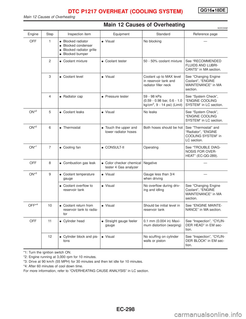
Main 12 Causes of OverheatingNCEC0492
Engine Step Inspection item Equipment Standard Reference page
OFF 1IBlocked radiator
IBlocked condenser
IBlocked radiator grille
IBlocked bumperIVisual No blocking Ð
2ICoolant mixtureICoolant tester 50 - 50% coolant mixture See ªRECOMMENDED
FLUIDS AND LUBRI-
CANTSº in MA section.
3ICoolant levelIVisual Coolant up to MAX level
in reservoir tank and
radiator filler neckSee ªChanging Engine
Coolantº, ªENGINE
MAINTENANCEº in MA
section.
4IRadiator capIPressure tester 59 - 98 kPa
(0.59 - 0.98 bar, 0.6 - 1.0
kg/cm
2,9-14psi) (Limit)See ªSystem Checkº,
ªENGINE COOLING
SYSTEMº in LC section.
ON*
25ICoolant leaksIVisual No leaks See ªSystem Checkº,
ªENGINE COOLING
SYSTEMº in LC section.
ON*
26IThermostatITouch the upper and
lower radiator hosesBoth hoses should be hot See ªThermostatº and
ªRadiatorº, ªENGINE
COOLING SYSTEMº in
LC section.
ON*
17ICooling fanICONSULT-II Operating See ªTROUBLE DIAG-
NOSIS FOR OVER-
HEATº (EC-QG-289).
OFF 8ICombustion gas leakIColor checker chemical
tester 4 Gas analyzerNegative Ð
ON*
39ICoolant temperature
gaugeIVisual Gauge less than 3/4
when drivingÐ
ICoolant overflow to
reservoir tankIVisual No overflow during driv-
ing and idlingSee ªChanging Engine
Coolantº, ªENGINE
MAINTENANCEº in MA
section.
OFF*
410ICoolant return from
reservoir tank to radia-
torIVisual Should be initial level in
reservoir tankSee ªENGINE MAINTE-
NANCEº in MA section.
OFF 11ICylinder headIStraight gauge feeler
gauge0.1 mm (0.004 in) Maxi-
mum distortion (warping)See ªInspectionº, ªCYLIN-
DER HEADº in EM sec-
tion.
12ICylinder block and pis-
tonsIVisual No scuffing on cylinder
walls or pistonSee ªInspectionº, ªCYLIN-
DER BLOCKº in EM sec-
tion.
*1: Turn the ignition switch ON.
*2: Engine running at 3,000 rpm for 10 minutes.
*3: Drive at 90 km/h (55 MPH) for 30 minutes and then let idle for 10 minutes.
*4: After 60 minutes of cool down time.
For more information, refer to ªOVERHEATING CAUSE ANALYSISº in LC section.
DTC P1217 OVERHEAT (COOLING SYSTEM)QG16I18DE
Main 12 Causes of Overheating
EC-298
Page 1080 of 2267
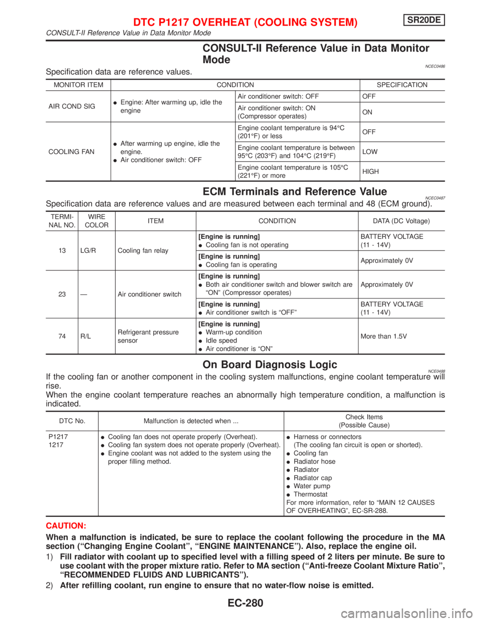
CONSULT-II Reference Value in Data Monitor
Mode
NCEC0486Specification data are reference values.
MONITOR ITEM CONDITION SPECIFICATION
AIR COND SIGIEngine: After warming up, idle the
engineAir conditioner switch: OFF OFF
Air conditioner switch: ON
(Compressor operates)ON
COOLING FANIAfter warming up engine, idle the
engine.
IAir conditioner switch: OFFEngine coolant temperature is 94ÉC
(201ÉF) or lessOFF
Engine coolant temperature is between
95ÉC (203ÉF) and 104ÉC (219ÉF)LOW
Engine coolant temperature is 105ÉC
(221ÉF) or moreHIGH
ECM Terminals and Reference ValueNCEC0487Specification data are reference values and are measured between each terminal and 48 (ECM ground).
TERMI-
NAL NO.WIRE
COLORITEM CONDITION DATA (DC Voltage)
13 LG/R Cooling fan relay[Engine is running]
ICooling fan is not operatingBATTERY VOLTAGE
(11 - 14V)
[Engine is running]
ICooling fan is operatingApproximately 0V
23 Ð Air conditioner switch[Engine is running]
IBoth air conditioner switch and blower switch are
ªONº (Compressor operates)Approximately 0V
[Engine is running]
IAir conditioner switch is ªOFFºBATTERY VOLTAGE
(11 - 14V)
74 R/LRefrigerant pressure
sensor[Engine is running]
IWarm-up condition
IIdle speed
IAir conditioner is ªONºMore than 1.5V
On Board Diagnosis LogicNCE0488If the cooling fan or another component in the cooling system malfunctions, engine coolant temperature will
rise.
When the engine coolant temperature reaches an abnormally high temperature condition, a malfunction is
indicated.
DTC No. Malfunction is detected when ...Check Items
(Possible Cause)
P1217
1217ICooling fan does not operate properly (Overheat).
ICooling fan system does not operate properly (Overheat).
IEngine coolant was not added to the system using the
proper filling method.IHarness or connectors
(The cooling fan circuit is open or shorted).
ICooling fan
IRadiator hose
IRadiator
IRadiator cap
IWater pump
IThermostat
For more information, refer to ªMAIN 12 CAUSES
OF OVERHEATINGº, EC-SR-288.
CAUTION:
When a malfunction is indicated, be sure to replace the coolant following the procedure in the MA
section (ªChanging Engine Coolantº, ªENGINE MAINTENANCEº). Also, replace the engine oil.
1)Fill radiator with coolant up to specified level with a filling speed of 2 liters per minute. Be sure to
use coolant with the proper mixture ratio. Refer to MA section (ªAnti-freeze Coolant Mixture Ratioº,
ªRECOMMENDED FLUIDS AND LUBRICANTSº).
2)After refilling coolant, run engine to ensure that no water-flow noise is emitted.
DTC P1217 OVERHEAT (COOLING SYSTEM)SR20DE
CONSULT-II Reference Value in Data Monitor Mode
EC-280
Page 1088 of 2267
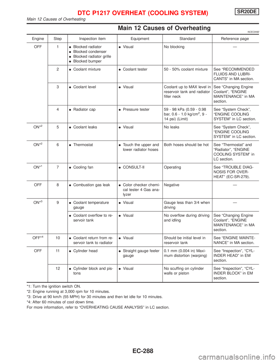
Main 12 Causes of OverheatingNCEC0492
Engine Step Inspection item Equipment Standard Reference page
OFF 1IBlocked radiator
IBlocked condenser
IBlocked radiator grille
IBlocked bumperIVisual No blocking Ð
2ICoolant mixtureICoolant tester 50 - 50% coolant mixture See ªRECOMMENDED
FLUIDS AND LUBRI-
CANTSº in MA section.
3ICoolant levelIVisual Coolant up to MAX level in
reservoir tank and radiator
filler neckSee ªChanging Engine
Coolantº, ªENGINE
MAINTENANCEº in MA
section.
4IRadiator capIPressure tester 59 - 98 kPa (0.59 - 0.98
bar, 0.6 - 1.0 kg/cm
2,9-
14 psi) (Limit)See ªSystem Checkº,
ªENGINE COOLING
SYSTEMº in LC section.
ON*
25ICoolant leaksIVisual No leaks See ªSystem Checkº,
ªENGINE COOLING
SYSTEMº in LC section.
ON*
26IThermostatITouch the upper and
lower radiator hosesBoth hoses should be hot See ªThermostatº and
ªRadiatorº, ªENGINE
COOLING SYSTEMº in
LC section.
ON*
17ICooling fanICONSULT-II Operating See ªTROUBLE DIAG-
NOSIS FOR OVER-
HEATº (EC-SR-279).
OFF 8ICombustion gas leakIColor checker chemi-
cal tester 4 Gas ana-
lyzerNegative Ð
ON*
39ICoolant temperature
gaugeIVisual Gauge less than 3/4 when
drivingÐ
ICoolant overflow to re-
servoir tankIVisual No overflow during driving
and idlingSee ªChanging Engine
Coolantº, ªENGINE
MAINTENANCEº in MA
section.
OFF*
410ICoolant return from re-
servoir tank to radiatorIVisual Should be initial level in
reservoir tankSee ªENGINE MAINTE-
NANCEº in MA section.
OFF 11ICylinder headIStraight gauge feeler
gauge0.1 mm (0.004 in) Maxi-
mum distortion (warping)See ªInspectionº, ªCYL-
INDER HEADº in EM
section.
12ICylinder block and pis-
tonsIVisual No scuffing on cylinder
walls or pistonSee ªInspectionº, ªCYL-
INDER BLOCKº in EM
section.
*1: Turn the ignition switch ON.
*2: Engine running at 3,000 rpm for 10 minutes.
*3: Drive at 90 km/h (55 MPH) for 30 minutes and then let idle for 10 minutes.
*4: After 60 minutes of cool down time.
For more information, refer to ªOVERHEATING CAUSE ANALYSISº in LC section.
DTC P1217 OVERHEAT (COOLING SYSTEM)SR20DE
Main 12 Causes of Overheating
EC-288
Page 1800 of 2267
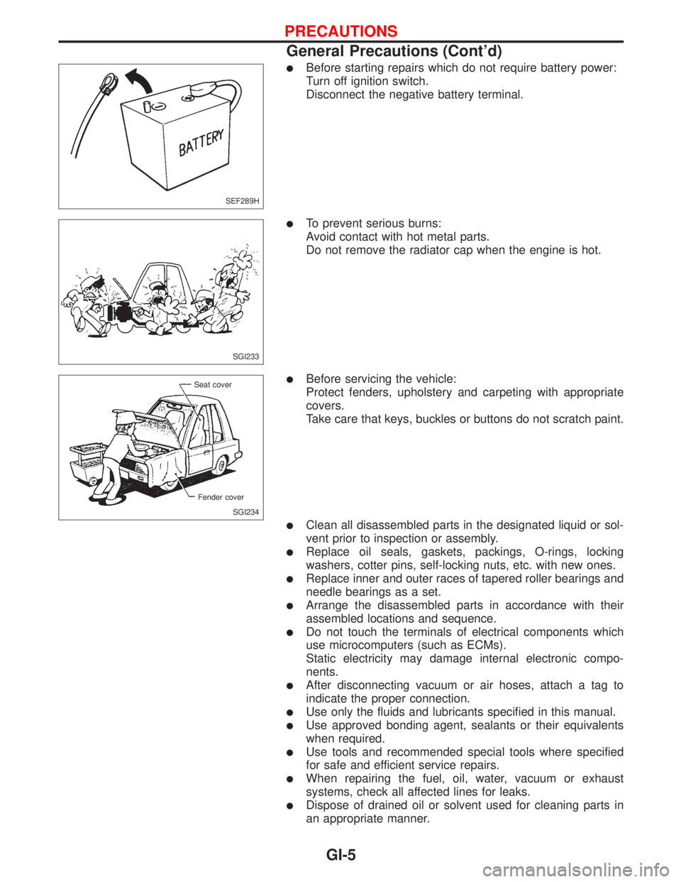
lBefore starting repairs which do not require battery power:
Turn off ignition switch.
Disconnect the negative battery terminal.
lTo prevent serious burns:
Avoid contact with hot metal parts.
Do not remove the radiator cap when the engine is hot.
lBefore servicing the vehicle:
Protect fenders, upholstery and carpeting with appropriate
covers.
Take care that keys, buckles or buttons do not scratch paint.
lClean all disassembled parts in the designated liquid or sol-
vent prior to inspection or assembly.
lReplace oil seals, gaskets, packings, O-rings, locking
washers, cotter pins, self-locking nuts, etc. with new ones.
lReplace inner and outer races of tapered roller bearings and
needle bearings as a set.
lArrange the disassembled parts in accordance with their
assembled locations and sequence.
lDo not touch the terminals of electrical components which
use microcomputers (such as ECMs).
Static electricity may damage internal electronic compo-
nents.
lAfter disconnecting vacuum or air hoses, attach a tag to
indicate the proper connection.
lUse only the fluids and lubricants specified in this manual.
lUse approved bonding agent, sealants or their equivalents
when required.
lUse tools and recommended special tools where specified
for safe and efficient service repairs.
lWhen repairing the fuel, oil, water, vacuum or exhaust
systems, check all affected lines for leaks.
lDispose of drained oil or solvent used for cleaning parts in
an appropriate manner.
SEF289H
SGI233
SGI234 Seat cover
Fender cover
PRECAUTIONS
General Precautions (Cont'd)
GI-5