1999 NISSAN PRIMERA diagram
[x] Cancel search: diagramPage 307 of 2267

Vacuum Hose Drawing
p1EGRC-solenoid valves A and B to EGR valve
p2EGRC-solenoid valves A and B to air duct
p3EGRC-solenoid valve A to vacuum pump
Refer to ªSystem Diagramº on previous page for vacuum control system.
YEC131A
ENGINE AND EMISSION CONTROL OVERALL SYSTEMCD20T
EC-13
Page 443 of 2267
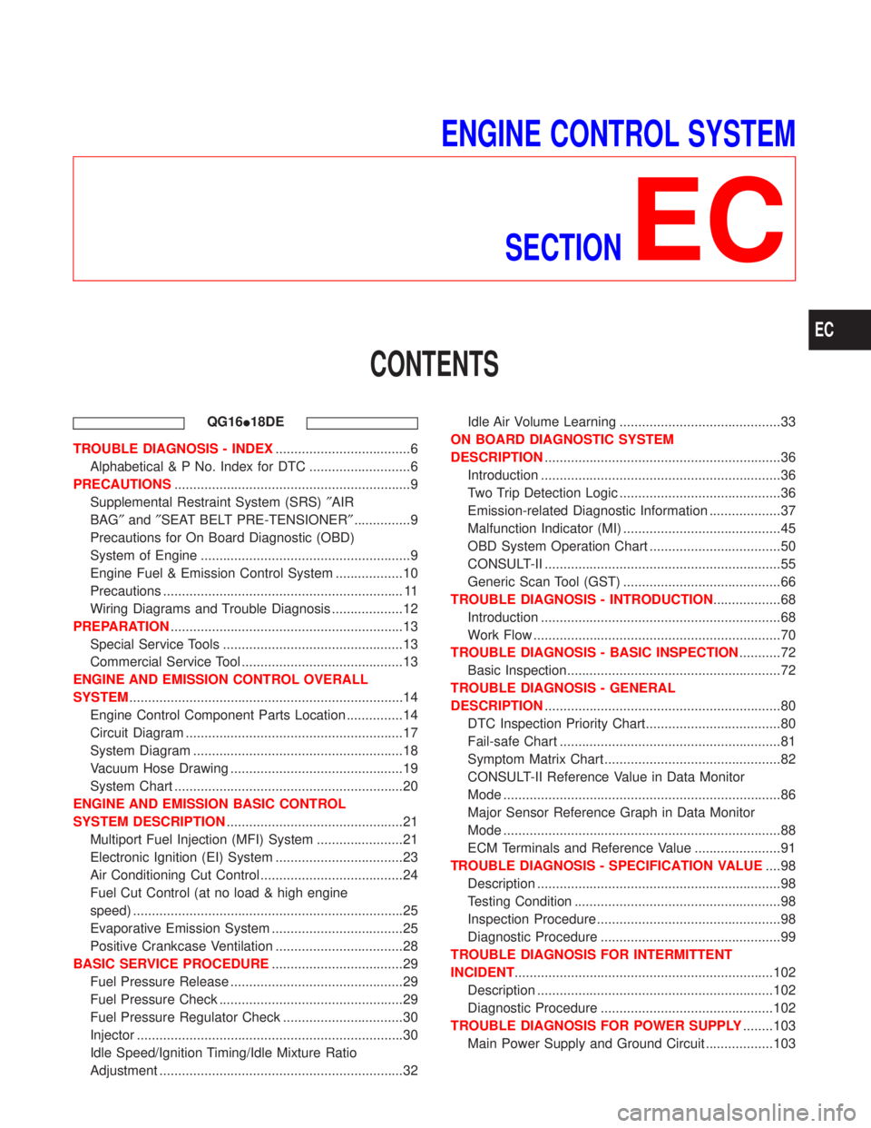
ENGINE CONTROL SYSTEM
SECTION
EC
CONTENTS
QG16I18DE
TROUBLE DIAGNOSIS - INDEX....................................6
Alphabetical & P No. Index for DTC ...........................6
PRECAUTIONS...............................................................9
Supplemental Restraint System (SRS)²AIR
BAG²and²SEAT BELT PRE-TENSIONER²...............9
Precautions for On Board Diagnostic (OBD)
System of Engine ........................................................9
Engine Fuel & Emission Control System ..................10
Precautions ................................................................ 11
Wiring Diagrams and Trouble Diagnosis ...................12
PREPARATION..............................................................13
Special Service Tools ................................................13
Commercial Service Tool ...........................................13
ENGINE AND EMISSION CONTROL OVERALL
SYSTEM.........................................................................14
Engine Control Component Parts Location ...............14
Circuit Diagram ..........................................................17
System Diagram ........................................................18
Vacuum Hose Drawing ..............................................19
System Chart .............................................................20
ENGINE AND EMISSION BASIC CONTROL
SYSTEM DESCRIPTION...............................................21
Multiport Fuel Injection (MFI) System .......................21
Electronic Ignition (EI) System ..................................23
Air Conditioning Cut Control ......................................24
Fuel Cut Control (at no load & high engine
speed) ........................................................................25
Evaporative Emission System ...................................25
Positive Crankcase Ventilation ..................................28
BASIC SERVICE PROCEDURE...................................29
Fuel Pressure Release ..............................................29
Fuel Pressure Check .................................................29
Fuel Pressure Regulator Check ................................30
Injector .......................................................................30
Idle Speed/Ignition Timing/Idle Mixture Ratio
Adjustment .................................................................32Idle Air Volume Learning ...........................................33
ON BOARD DIAGNOSTIC SYSTEM
DESCRIPTION...............................................................36
Introduction ................................................................36
Two Trip Detection Logic ...........................................36
Emission-related Diagnostic Information ...................37
Malfunction Indicator (MI) ..........................................45
OBD System Operation Chart ...................................50
CONSULT-II ...............................................................55
Generic Scan Tool (GST) ..........................................66
TROUBLE DIAGNOSIS - INTRODUCTION..................68
Introduction ................................................................68
Work Flow ..................................................................70
TROUBLE DIAGNOSIS - BASIC INSPECTION...........72
Basic Inspection.........................................................72
TROUBLE DIAGNOSIS - GENERAL
DESCRIPTION...............................................................80
DTC Inspection Priority Chart....................................80
Fail-safe Chart ...........................................................81
Symptom Matrix Chart ...............................................82
CONSULT-II Reference Value in Data Monitor
Mode ..........................................................................86
Major Sensor Reference Graph in Data Monitor
Mode ..........................................................................88
ECM Terminals and Reference Value .......................91
TROUBLE DIAGNOSIS - SPECIFICATION VALUE....98
Description .................................................................98
Testing Condition .......................................................98
Inspection Procedure .................................................98
Diagnostic Procedure ................................................99
TROUBLE DIAGNOSIS FOR INTERMITTENT
INCIDENT.....................................................................102
Description ...............................................................102
Diagnostic Procedure ..............................................102
TROUBLE DIAGNOSIS FOR POWER SUPPLY........103
Main Power Supply and Ground Circuit ..................103
EC
Page 444 of 2267
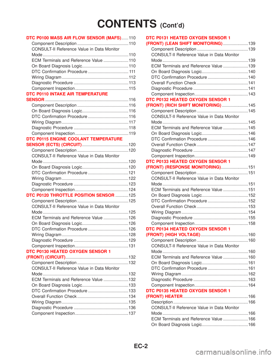
DTC P0100 MASS AIR FLOW SENSOR (MAFS)...... 110
Component Description ........................................... 110
CONSULT-II Reference Value in Data Monitor
Mode ........................................................................ 110
ECM Terminals and Reference Value ..................... 110
On Board Diagnosis Logic....................................... 110
DTC Confirmation Procedure .................................. 111
Wiring Diagram ........................................................ 112
Diagnostic Procedure .............................................. 113
Component Inspection ............................................. 115
DTC P0110 INTAKE AIR TEMPERATURE
SENSOR...................................................................... 116
Component Description ........................................... 116
On Board Diagnosis Logic....................................... 116
DTC Confirmation Procedure .................................. 116
Wiring Diagram ........................................................ 117
Diagnostic Procedure .............................................. 118
Component Inspection ............................................. 119
DTC P0115 ENGINE COOLANT TEMPERATURE
SENSOR (ECTS) (CIRCUIT).......................................120
Component Description ...........................................120
CONSULT-II Reference Value in Data Monitor
Mode ........................................................................120
On Board Diagnosis Logic.......................................120
DTC Confirmation Procedure ..................................121
Wiring Diagram ........................................................122
Diagnostic Procedure ..............................................123
Component Inspection .............................................124
DTC P0120 THROTTLE POSITION SENSOR...........125
Component Description ...........................................125
CONSULT-II Reference Value in Data Monitor
Mode ........................................................................125
ECM Terminals and Reference Value .....................126
On Board Diagnosis Logic.......................................126
DTC Confirmation Procedure ..................................126
Wiring Diagram ........................................................128
Diagnostic Procedure ..............................................129
Component Inspection .............................................131
DTC P0130 HEATED OXYGEN SENSOR 1
(FRONT) (CIRCUIT).....................................................132
Component Description ...........................................132
CONSULT-II Reference Value in Data Monitor
Mode ........................................................................132
ECM Terminals and Reference Value .....................132
On Board Diagnosis Logic.......................................133
DTC Confirmation Procedure ..................................133
Overall Function Check ...........................................134
Wiring Diagram ........................................................135
Diagnostic Procedure ..............................................136
Component Inspection .............................................137DTC P0131 HEATED OXYGEN SENSOR 1
(FRONT) (LEAN SHIFT MONITORING).....................139
Component Description ...........................................139
CONSULT-II Reference Value in Data Monitor
Mode ........................................................................139
ECM Terminals and Reference Value .....................139
On Board Diagnosis Logic.......................................140
DTC Confirmation Procedure ..................................140
Overall Function Check ...........................................141
Diagnostic Procedure ..............................................141
Component Inspection .............................................143
DTC P0132 HEATED OXYGEN SENSOR 1
(FRONT) (RICH SHIFT MONITORING)......................145
Component Description ...........................................145
CONSULT-II Reference Value in Data Monitor
Mode ........................................................................145
ECM Terminals and Reference Value .....................145
On Board Diagnosis Logic.......................................146
DTC Confirmation Procedure ..................................146
Overall Function Check ...........................................147
Diagnostic Procedure ..............................................147
Component Inspection .............................................149
DTC P0133 HEATED OXYGEN SENSOR 1
(FRONT) (RESPONSE MONITORING).......................151
Component Description ...........................................151
CONSULT-II Reference Value in Data Monitor
Mode ........................................................................151
ECM Terminals and Reference Value .....................151
On Board Diagnosis Logic.......................................152
DTC Confirmation Procedure ..................................152
Overall Function Check ...........................................153
Wiring Diagram ........................................................154
Diagnostic Procedure ..............................................155
Component Inspection .............................................158
DTC P0134 HEATED OXYGEN SENSOR 1
(FRONT) (HIGH VOLTAGE)........................................160
Component Description ...........................................160
CONSULT-II Reference Value in Data Monitor
Mode ........................................................................160
ECM Terminals and Reference Value .....................160
On Board Diagnosis Logic.......................................161
DTC Confirmation Procedure ..................................161
Wiring Diagram ........................................................162
Diagnostic Procedure ..............................................163
Component Inspection .............................................164
DTC P0135 HEATED OXYGEN SENSOR 1
(FRONT) HEATER.......................................................166
Description ...............................................................166
CONSULT-II Reference Value in Data Monitor
Mode ........................................................................166
ECM Terminals and Reference Value .....................166
On Board Diagnosis Logic.......................................166
CONTENTS(Cont'd)
EC-2
Page 445 of 2267
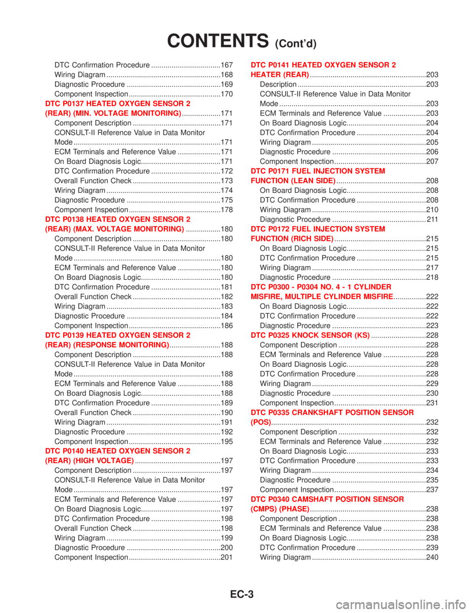
DTC Confirmation Procedure ..................................167
Wiring Diagram ........................................................168
Diagnostic Procedure ..............................................169
Component Inspection .............................................170
DTC P0137 HEATED OXYGEN SENSOR 2
(REAR) (MIN. VOLTAGE MONITORING)...................171
Component Description ...........................................171
CONSULT-II Reference Value in Data Monitor
Mode ........................................................................171
ECM Terminals and Reference Value .....................171
On Board Diagnosis Logic.......................................171
DTC Confirmation Procedure ..................................172
Overall Function Check ...........................................173
Wiring Diagram ........................................................174
Diagnostic Procedure ..............................................175
Component Inspection .............................................178
DTC P0138 HEATED OXYGEN SENSOR 2
(REAR) (MAX. VOLTAGE MONITORING).................180
Component Description ...........................................180
CONSULT-II Reference Value in Data Monitor
Mode ........................................................................180
ECM Terminals and Reference Value .....................180
On Board Diagnosis Logic.......................................180
DTC Confirmation Procedure ..................................181
Overall Function Check ...........................................182
Wiring Diagram ........................................................183
Diagnostic Procedure ..............................................184
Component Inspection .............................................186
DTC P0139 HEATED OXYGEN SENSOR 2
(REAR) (RESPONSE MONITORING).........................188
Component Description ...........................................188
CONSULT-II Reference Value in Data Monitor
Mode ........................................................................188
ECM Terminals and Reference Value .....................188
On Board Diagnosis Logic.......................................188
DTC Confirmation Procedure ..................................189
Overall Function Check ...........................................190
Wiring Diagram ........................................................191
Diagnostic Procedure ..............................................192
Component Inspection .............................................195
DTC P0140 HEATED OXYGEN SENSOR 2
(REAR) (HIGH VOLTAGE)..........................................197
Component Description ...........................................197
CONSULT-II Reference Value in Data Monitor
Mode ........................................................................197
ECM Terminals and Reference Value .....................197
On Board Diagnosis Logic.......................................197
DTC Confirmation Procedure ..................................198
Overall Function Check ...........................................198
Wiring Diagram ........................................................199
Diagnostic Procedure ..............................................200
Component Inspection .............................................201DTC P0141 HEATED OXYGEN SENSOR 2
HEATER (REAR).........................................................203
Description ...............................................................203
CONSULT-II Reference Value in Data Monitor
Mode ........................................................................203
ECM Terminals and Reference Value .....................203
On Board Diagnosis Logic.......................................204
DTC Confirmation Procedure ..................................204
Wiring Diagram ........................................................205
Diagnostic Procedure ..............................................206
Component Inspection .............................................207
DTC P0171 FUEL INJECTION SYSTEM
FUNCTION (LEAN SIDE)............................................208
On Board Diagnosis Logic.......................................208
DTC Confirmation Procedure ..................................208
Wiring Diagram ........................................................210
Diagnostic Procedure .............................................. 211
DTC P0172 FUEL INJECTION SYSTEM
FUNCTION (RICH SIDE).............................................215
On Board Diagnosis Logic.......................................215
DTC Confirmation Procedure ..................................215
Wiring Diagram ........................................................217
Diagnostic Procedure ..............................................218
DTC P0300 - P0304 NO.4-1CYLINDER
MISFIRE, MULTIPLE CYLINDER MISFIRE................222
On Board Diagnosis Logic.......................................222
DTC Confirmation Procedure ..................................222
Diagnostic Procedure ..............................................223
DTC P0325 KNOCK SENSOR (KS)...........................228
Component Description ...........................................228
ECM Terminals and Reference Value .....................228
On Board Diagnosis Logic.......................................228
DTC Confirmation Procedure ..................................228
Wiring Diagram ........................................................229
Diagnostic Procedure ..............................................230
Component Inspection .............................................231
DTC P0335 CRANKSHAFT POSITION SENSOR
(POS)............................................................................232
Component Description ...........................................232
ECM Terminals and Reference Value .....................232
On Board Diagnosis Logic.......................................233
DTC Confirmation Procedure ..................................233
Wiring Diagram ........................................................234
Diagnostic Procedure ..............................................235
Component Inspection .............................................237
DTC P0340 CAMSHAFT POSITION SENSOR
(CMPS) (PHASE).........................................................238
Component Description ...........................................238
ECM Terminals and Reference Value .....................238
On Board Diagnosis Logic.......................................238
DTC Confirmation Procedure ..................................239
Wiring Diagram ........................................................240
CONTENTS(Cont'd)
EC-3
Page 446 of 2267
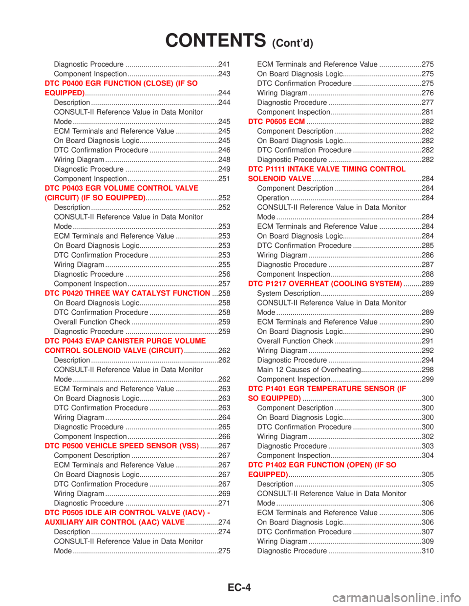
Diagnostic Procedure ..............................................241
Component Inspection .............................................243
DTC P0400 EGR FUNCTION (CLOSE) (IF SO
EQUIPPED)..................................................................244
Description ...............................................................244
CONSULT-II Reference Value in Data Monitor
Mode ........................................................................245
ECM Terminals and Reference Value .....................245
On Board Diagnosis Logic.......................................245
DTC Confirmation Procedure ..................................246
Wiring Diagram ........................................................248
Diagnostic Procedure ..............................................249
Component Inspection .............................................251
DTC P0403 EGR VOLUME CONTROL VALVE
(CIRCUIT) (IF SO EQUIPPED)....................................252
Description ...............................................................252
CONSULT-II Reference Value in Data Monitor
Mode ........................................................................253
ECM Terminals and Reference Value .....................253
On Board Diagnosis Logic.......................................253
DTC Confirmation Procedure ..................................253
Wiring Diagram ........................................................255
Diagnostic Procedure ..............................................256
Component Inspection .............................................257
DTC P0420 THREE WAY CATALYST FUNCTION...258
On Board Diagnosis Logic.......................................258
DTC Confirmation Procedure ..................................258
Overall Function Check ...........................................259
Diagnostic Procedure ..............................................259
DTC P0443 EVAP CANISTER PURGE VOLUME
CONTROL SOLENOID VALVE (CIRCUIT).................262
Description ...............................................................262
CONSULT-II Reference Value in Data Monitor
Mode ........................................................................262
ECM Terminals and Reference Value .....................263
On Board Diagnosis Logic.......................................263
DTC Confirmation Procedure ..................................263
Wiring Diagram ........................................................264
Diagnostic Procedure ..............................................265
Component Inspection .............................................266
DTC P0500 VEHICLE SPEED SENSOR (VSS).........267
Component Description ...........................................267
ECM Terminals and Reference Value .....................267
On Board Diagnosis Logic.......................................267
DTC Confirmation Procedure ..................................267
Wiring Diagram ........................................................269
Diagnostic Procedure ..............................................271
DTC P0505 IDLE AIR CONTROL VALVE (IACV) -
AUXILIARY AIR CONTROL (AAC) VALVE................274
Description ...............................................................274
CONSULT-II Reference Value in Data Monitor
Mode ........................................................................275ECM Terminals and Reference Value .....................275
On Board Diagnosis Logic.......................................275
DTC Confirmation Procedure ..................................275
Wiring Diagram ........................................................276
Diagnostic Procedure ..............................................277
Component Inspection .............................................281
DTC P0605 ECM.........................................................282
Component Description ...........................................282
On Board Diagnosis Logic.......................................282
DTC Confirmation Procedure ..................................282
Diagnostic Procedure ..............................................282
D T C P 1111 I N TA K E VA LV ETIMING CONTROL
SOLENOID VALVE......................................................284
Component Description ...........................................284
Operation .................................................................284
CONSULT-II Reference Value in Data Monitor
Mode ........................................................................284
ECM Terminals and Reference Value .....................284
On Board Diagnosis Logic.......................................284
DTC Confirmation Procedure ..................................285
Wiring Diagram ........................................................286
Diagnostic Procedure ..............................................287
Component Inspection .............................................288
DTC P1217 OVERHEAT (COOLING SYSTEM).........289
System Description ..................................................289
CONSULT-II Reference Value in Data Monitor
Mode ........................................................................289
ECM Terminals and Reference Value .....................290
On Board Diagnosis Logic.......................................290
Overall Function Check ...........................................291
Wiring Diagram ........................................................292
Diagnostic Procedure ..............................................294
Main 12 Causes of Overheating..............................298
Component Inspection .............................................299
DTC P1401 EGR TEMPERATURE SENSOR (IF
SO EQUIPPED)...........................................................300
Component Description ...........................................300
On Board Diagnosis Logic.......................................300
DTC Confirmation Procedure ..................................300
Wiring Diagram ........................................................302
Diagnostic Procedure ..............................................303
Component Inspection .............................................304
DTC P1402 EGR FUNCTION (OPEN) (IF SO
EQUIPPED)..................................................................305
Description ...............................................................305
CONSULT-II Reference Value in Data Monitor
Mode ........................................................................306
ECM Terminals and Reference Value .....................306
On Board Diagnosis Logic.......................................306
DTC Confirmation Procedure ..................................307
Wiring Diagram ........................................................309
Diagnostic Procedure ..............................................310
CONTENTS(Cont'd)
EC-4
Page 447 of 2267
Component Inspection ............................................. 311
DTC P1706 PARK/NEUTRAL POSITION (PNP)
SWITCH.......................................................................313
Component Description ...........................................313
CONSULT-II Reference Value in Data Monitor
Mode ........................................................................313
ECM Terminals and Reference Value .....................313
On Board Diagnosis Logic.......................................313
DTC Confirmation Procedure ..................................313
Overall Function Check ...........................................314
Wiring Diagram ........................................................315
Diagnostic Procedure For M/T Models....................316
INJECTOR...................................................................318
Component Description ...........................................318
CONSULT-II Reference Value in Data Monitor
Mode ........................................................................318
ECM Terminals and Reference Value .....................318
Wiring Diagram ........................................................319
Diagnostic Procedure ..............................................320
Component Inspection .............................................322
IGNITION SIGNAL.......................................................323
Component Description ...........................................323
CONSULT-II Reference Value in Data Monitor
Mode ........................................................................323
ECM Terminals and Reference Value .....................323
Wiring Diagram ........................................................324
Diagnostic Procedure ..............................................326
Component Inspection .............................................331
START SIGNAL...........................................................332
CONSULT-II Reference Value in Data Monitor
Mode ........................................................................332
ECM Terminals and Reference Value .....................332
Wiring Diagram ........................................................333
Diagnostic Procedure ..............................................334
FUEL PUMP.................................................................336
System Description ..................................................336
Component Description ...........................................336
CONSULT-II Reference Value in Data Monitor
Mode ........................................................................336
ECM Terminals and Reference Value .....................337
Wiring Diagram ........................................................338
Diagnostic Procedure ..............................................339Component Inspection .............................................341
POWER STEERING OIL PRESSURE SWITCH.........342
Component Description ...........................................342
CONSULT-II Reference Value in Data Monitor
Mode ........................................................................342
ECM Terminals and Reference Value .....................342
Wiring Diagram ........................................................343
Diagnostic Procedure ..............................................344
Component Inspection .............................................346
REFRIGERANT PRESSURE SENSOR......................347
Description ...............................................................347
ECM Terminals and Reference Value .....................347
Wiring Diagram ........................................................348
Diagnostic Procedure ..............................................349
ELECTRICAL LOAD SIGNAL.....................................351
CONSULT-II Reference Value in Data Monitor
Mode ........................................................................351
ECM Terminals and Reference Value .....................351
Wiring Diagram ........................................................352
MI & DATA LINK CONNECTORS...............................354
Wiring Diagram ........................................................354
SERVICE DATA AND SPECIFICATIONS (SDS)........355
Fuel Pressure Regulator..........................................355
Idle Speed and Ignition Timing ................................355
Mass Air Flow Sensor..............................................355
Intake Air Temperature Sensor ................................355
Engine Coolant Temperature Sensor ......................355
Throttle Position Sensor ..........................................355
Heated Oxygen Sensor 1 Heater (Front) ................355
Heated Oxygen Sensor 2 Heater (Rear).................355
Crankshaft Position Sensor (POS) ..........................356
Camshaft Position Sensor (PHASE) .......................356
EGR Volume Control Valve (If so equipped)...........356
EGR Temperature Sensor (If so equipped).............356
EVAP Canister Purge Volume Control Valve ..........356
IACV-AAC Valve ......................................................356
Injector .....................................................................356
Ignition Coil with Power Transistor ..........................357
Fuel Pump ...............................................................357
CONTENTS(Cont'd)
EC-5
Page 454 of 2267
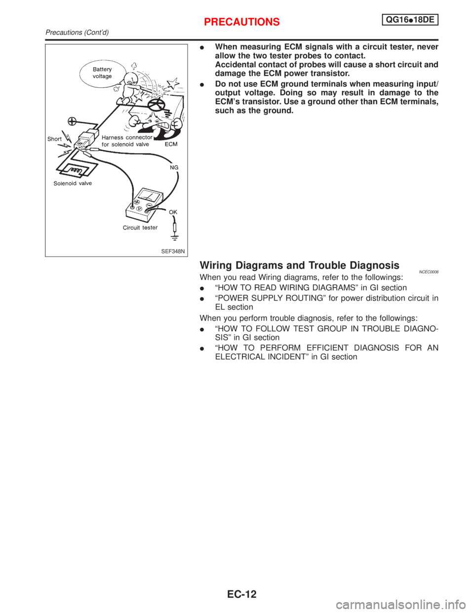
IWhen measuring ECM signals with a circuit tester, never
allow the two tester probes to contact.
Accidental contact of probes will cause a short circuit and
damage the ECM power transistor.
IDo not use ECM ground terminals when measuring input/
output voltage. Doing so may result in damage to the
ECM's transistor. Use a ground other than ECM terminals,
such as the ground.
Wiring Diagrams and Trouble DiagnosisNCEC0006When you read Wiring diagrams, refer to the followings:
IªHOW TO READ WIRING DIAGRAMSº in GI section
IªPOWER SUPPLY ROUTINGº for power distribution circuit in
EL section
When you perform trouble diagnosis, refer to the followings:
IªHOW TO FOLLOW TEST GROUP IN TROUBLE DIAGNO-
SISº in GI section
IªHOW TO PERFORM EFFICIENT DIAGNOSIS FOR AN
ELECTRICAL INCIDENTº in GI section
SEF348N
PRECAUTIONSQG16I18DE
Precautions (Cont'd)
EC-12
Page 459 of 2267

Circuit DiagramNCEC0010
YEC062A
ENGINE AND EMISSION CONTROL OVERALL SYSTEMQG16I18DE
Circuit Diagram
EC-17