Page 611 of 2267

Diagnostic ProcedureNLEC0142
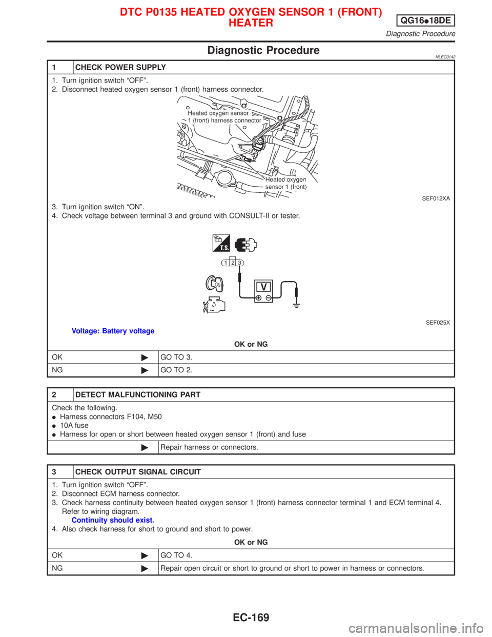
1 CHECK POWER SUPPLY
1. Turn ignition switch ªOFFº.
2. Disconnect heated oxygen sensor 1 (front) harness connector.
SEF012XA
3. Turn ignition switch ªONº.
4. Check voltage between terminal 3 and ground with CONSULT-II or tester.
SEF025X
Voltage: Battery voltage
OK or NG
OK©GO TO 3.
NG©GO TO 2.
2 DETECT MALFUNCTIONING PART
Check the following.
IHarness connectors F104, M50
I10A fuse
IHarness for open or short between heated oxygen sensor 1 (front) and fuse
©Repair harness or connectors.
3 CHECK OUTPUT SIGNAL CIRCUIT
1. Turn ignition switch ªOFFº.
2. Disconnect ECM harness connector.
3. Check harness continuity between heated oxygen sensor 1 (front) harness connector terminal 1 and ECM terminal 4.
Refer to wiring diagram.
Continuity should exist.
4. Also check harness for short to ground and short to power.
OK or NG
OK©GO TO 4.
NG©Repair open circuit or short to ground or short to power in harness or connectors.
DTC P0135 HEATED OXYGEN SENSOR 1 (FRONT)
HEATERQG16I18DE
Diagnostic Procedure
EC-169
Page 616 of 2267
Wiring DiagramNCEC0150
YEC067A
DTC P0137 HEATED OXYGEN SENSOR 2 (REAR)
(MIN. VOLTAGE MONITORING)QG16I18DE
Wiring Diagram
EC-174
Page 619 of 2267

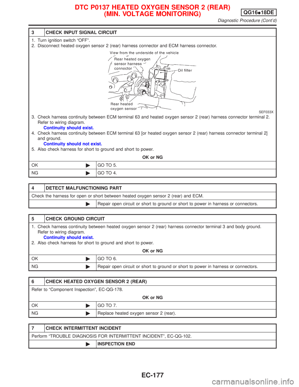
3 CHECK INPUT SIGNAL CIRCUIT
1. Turn ignition switch ªOFFº.
2. Disconnect heated oxygen sensor 2 (rear) harness connector and ECM harness connector.
SEF033X
3. Check harness continuity between ECM terminal 63 and heated oxygen sensor 2 (rear) harness connector terminal 2.
Refer to wiring diagram.
Continuity should exist.
4. Check harness continuity between ECM terminal 63 [or heated oxygen sensor 2 (rear) harness connector terminal 2]
and ground.
Continuity should not exist.
5. Also check harness for short to ground and short to power.
OK or NG
OK©GO TO 5.
NG©GO TO 4.
4 DETECT MALFUNCTIONING PART
Check the harness for open or short between heated oxygen sensor 2 (rear) and ECM.
©Repair open circuit or short to ground or short to power in harness or connectors.
5 CHECK GROUND CIRCUIT
1. Check harness continuity between heated oxygen sensor 2 (rear) harness connector terminal 3 and body ground.
Refer to wiring diagram.
Continuity should exist.
2. Also check harness for short to ground and short to power.
OK or NG
OK©GO TO 6.
NG©Repair open circuit or short to ground or short to power in harness or connectors.
6 CHECK HEATED OXYGEN SENSOR 2 (REAR)
Refer to ªComponent Inspectionº, EC-QG-178.
OK or NG
OK©GO TO 7.
NG©Replace heated oxygen sensor 2 (rear).
7 CHECK INTERMITTENT INCIDENT
Perform ªTROUBLE DIAGNOSIS FOR INTERMITTENT INCIDENTº, EC-QG-102.
©INSPECTION END
DTC P0137 HEATED OXYGEN SENSOR 2 (REAR)
(MIN. VOLTAGE MONITORING)QG16I18DE
Diagnostic Procedure (Cont'd)
EC-177
Page 625 of 2267
Wiring DiagramNCEC0159
YEC067A
DTC P0138 HEATED OXYGEN SENSOR 2 (REAR)
(MAX. VOLTAGE MONITORING)QG16I18DE
Wiring Diagram
EC-183
Page 628 of 2267

3 CHECK INPUT SIGNAL CIRCUIT
1. Disconnect heated oxygen sensor 2 (rear) harness connector and ECM harness connector.
2. Check harness continuity between ECM terminal 63 and heated oxygen sensor 2 (rear) harness connector terminal 2.
Refer to wiring diagram.
Continuity should exist.
3. Check harness continuity between ECM terminal 63 [or heated oxygen sensor 2 (rear) harness connector terminal 2]
and ground.
Continuity should not exist.
4. Also check harness for short to ground and short to power.
OK or NG
OK©GO TO 5.
NG©GO TO 4.
4 DETECT MALFUNCTIONING PART
Check the harness for open or short between ECM and heated oxygen sensor 2 (rear).
©Repair open circuit or short to ground or short to power in harness or connectors.
5 CHECK GROUND CIRCUIT
1. Check harness continuity between heated oxygen sensor 2 (rear) harness connector terminal 3 and engine ground.
Refer to wiring diagram.
Continuity should exist.
2. Also check harness for short to power.
OK or NG
OK©GO TO 6.
NG©Repair open circuit or short to power in harness or connectors.
6 CHECK HEATED OXYGEN SENSOR 2 (REAR)
Refer to ªComponent Inspectionº, EC-QG-186.
OK or NG
OK©GO TO 7.
NG©Replace heated oxygen sensor 2 (rear).
7 CHECK INTERMITTENT INCIDENT
Perform ªTROUBLE DIAGNOSIS FOR INTERMITTENT INCIDENTº, EC-QG-102.
©INSPECTION END
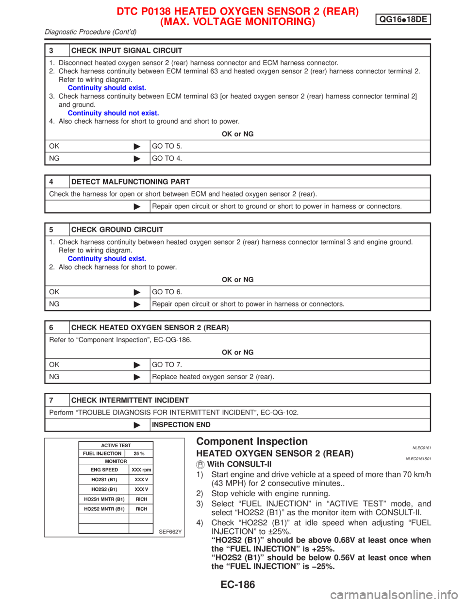
Component InspectionNLEC0161HEATED OXYGEN SENSOR 2 (REAR)NLEC0161S01With CONSULT-II
1) Start engine and drive vehicle at a speed of more than 70 km/h
(43 MPH) for 2 consecutive minutes..
2) Stop vehicle with engine running.
3) Select ªFUEL INJECTIONº in ªACTIVE TESTº mode, and
select ªHO2S2 (B1)º as the monitor item with CONSULT-II.
4) Check ªHO2S2 (B1)º at idle speed when adjusting ªFUEL
INJECTIONº to 25%.
ªHO2S2 (B1)º should be above 0.68V at least once when
the ªFUEL INJECTIONº is +25%.
ªHO2S2 (B1)º should be below 0.56V at least once when
the ªFUEL INJECTIONº is þ25%.
SEF662Y
DTC P0138 HEATED OXYGEN SENSOR 2 (REAR)
(MAX. VOLTAGE MONITORING)QG16I18DE
Diagnostic Procedure (Cont'd)
EC-186
Page 633 of 2267
Wiring DiagramNCEC0168
YEC067A
DTC P0139 HEATED OXYGEN SENSOR 2 (REAR)
(RESPONSE MONITORING)QG16I18DE
Wiring Diagram
EC-191
Page 636 of 2267

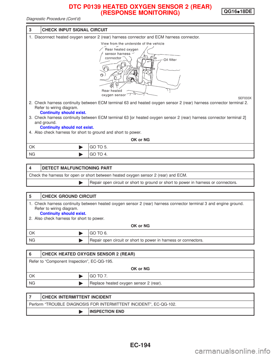
3 CHECK INPUT SIGNAL CIRCUIT
1. Disconnect heated oxygen sensor 2 (rear) harness connector and ECM harness connector.
SEF033X
2. Check harness continuity between ECM terminal 63 and heated oxygen sensor 2 (rear) harness connector terminal 2.
Refer to wiring diagram.
Continuity should exist.
3. Check harness continuity between ECM terminal 63 [or heated oxygen sensor 2 (rear) harness connector terminal 2]
and ground.
Continuity should not exist.
4. Also check harness for short to ground and short to power.
OK or NG
OK©GO TO 5.
NG©GO TO 4.
4 DETECT MALFUNCTIONING PART
Check the harness for open or short between heated oxygen sensor 2 (rear) and ECM.
©Repair open circuit or short to ground or short to power in harness or connectors.
5 CHECK GROUND CIRCUIT
1. Check harness continuity between heated oxygen sensor 2 (rear) harness connector terminal 3 and engine ground.
Refer to wiring diagram.
Continuity should exist.
2. Also check harness for short to power.
OK or NG
OK©GO TO 6.
NG©Repair open circuit or short to power in harness or connectors.
6 CHECK HEATED OXYGEN SENSOR 2 (REAR)
Refer to ªComponent Inspectionº, EC-QG-195.
OK or NG
OK©GO TO 7.
NG©Replace heated oxygen sensor 2 (rear).
7 CHECK INTERMITTENT INCIDENT
Perform ªTROUBLE DIAGNOSIS FOR INTERMITTENT INCIDENTº, EC-QG-102.
©INSPECTION END
DTC P0139 HEATED OXYGEN SENSOR 2 (REAR)
(RESPONSE MONITORING)QG16I18DE
Diagnostic Procedure (Cont'd)
EC-194
Page 641 of 2267
Wiring DiagramNCEC0177
YEC067A
DTC P0140 HEATED OXYGEN SENSOR 2 (REAR)
(HIGH VOLTAGE)QG16I18DE
Wiring Diagram
EC-199