Page 697 of 2267
Wiring DiagramNCEC0510
YEC782
: Detectable line for DTC
: Non-detectable line for DTC
ECM ECM RELAYEGR
VOLUME
CONTROL
VA LV E Refer to
EL-POWER. BATTERY
DTC P0403 EGR VOLUME CONTROL VALVE (CIRCUIT)
(IF SO EQUIPPED)QG16I18DE
Wiring Diagram
EC-255
Page 698 of 2267

Diagnostic ProcedureNCEC0511
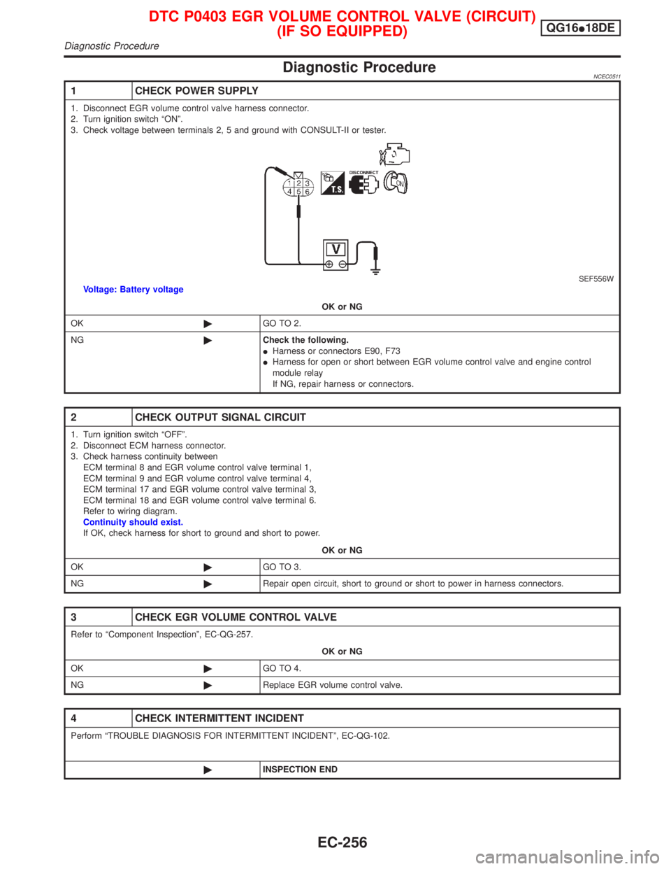
1 CHECK POWER SUPPLY
1. Disconnect EGR volume control valve harness connector.
2. Turn ignition switch ªONº.
3. Check voltage between terminals 2, 5 and ground with CONSULT-II or tester.
SEF556WVoltage: Battery voltage
OK or NG
OK©GO TO 2.
NG©Check the following.
IHarness or connectors E90, F73
IHarness for open or short between EGR volume control valve and engine control
module relay
If NG, repair harness or connectors.
2 CHECK OUTPUT SIGNAL CIRCUIT
1. Turn ignition switch ªOFFº.
2. Disconnect ECM harness connector.
3. Check harness continuity between
ECM terminal 8 and EGR volume control valve terminal 1,
ECM terminal 9 and EGR volume control valve terminal 4,
ECM terminal 17 and EGR volume control valve terminal 3,
ECM terminal 18 and EGR volume control valve terminal 6.
Refer to wiring diagram.
Continuity should exist.
If OK, check harness for short to ground and short to power.
OK or NG
OK©GO TO 3.
NG©Repair open circuit, short to ground or short to power in harness connectors.
3 CHECK EGR VOLUME CONTROL VALVE
Refer to ªComponent Inspectionº, EC-QG-257.
OK or NG
OK©GO TO 4.
NG©Replace EGR volume control valve.
4 CHECK INTERMITTENT INCIDENT
Perform ªTROUBLE DIAGNOSIS FOR INTERMITTENT INCIDENTº, EC-QG-102.
©INSPECTION END
DTC P0403 EGR VOLUME CONTROL VALVE (CIRCUIT)
(IF SO EQUIPPED)QG16I18DE
Diagnostic Procedure
EC-256
Page 702 of 2267
3 CHECK INTAKE AIR LEAK
Listen for an intake air leak after the mass air flow sensor.
OK or NG
OK©GO TO 4.
NG©Repair or replace.
4 CHECK IGNITION TIMING
Check for ignition timing.
Refer to TROUBLE DIAGNOSIS Ð ªBASIC INSPECTIONº, EC-QG-72.
OK or NG
OK©GO TO 5.
NG©Check camshaft position sensor (PHASE) (EC-QG-238) and crankshaft position sensor
(POS) (EC-QG-232).
5 CHECK INJECTORS
1. Refer to Wiring Diagram for Injectors, EC-QG-319.
2. Stop engine and then turn ignition switch ªONº.
3. Check voltage between ECM terminals 101, 103, 105 and 107 and ground with CONSULT-II or tester.
SEF075XBattery voltage should exist.
OK or NG
OK©GO TO 6.
NG©Perform ªDiagnostic Procedureº INJECTOR, EC-QG-320.
DTC P0420 THREE WAY CATALYST FUNCTIONQG16I18DE
Diagnostic Procedure (Cont'd)
EC-260
Page 706 of 2267
Wiring DiagramNCEC0253
YEC783
: Detectable line for DTC
: Non-detectable line for DTC
ECM EVAP CANISTER
PURGE VOLUME
CONTROL SOLENOID
VA LV EFUSE
BLOCK
(J/B)Refer to EL-POWER. IGNITION SWITCH
ON or START
Refer to last page (Foldout page)
DTC P0443 EVAP CANISTER PURGE VOLUME CONTROL
SOLENOID VALVE (CIRCUIT)QG16I18DE
Wiring Diagram
EC-264
Page 707 of 2267

Diagnostic ProcedureNCEC0254
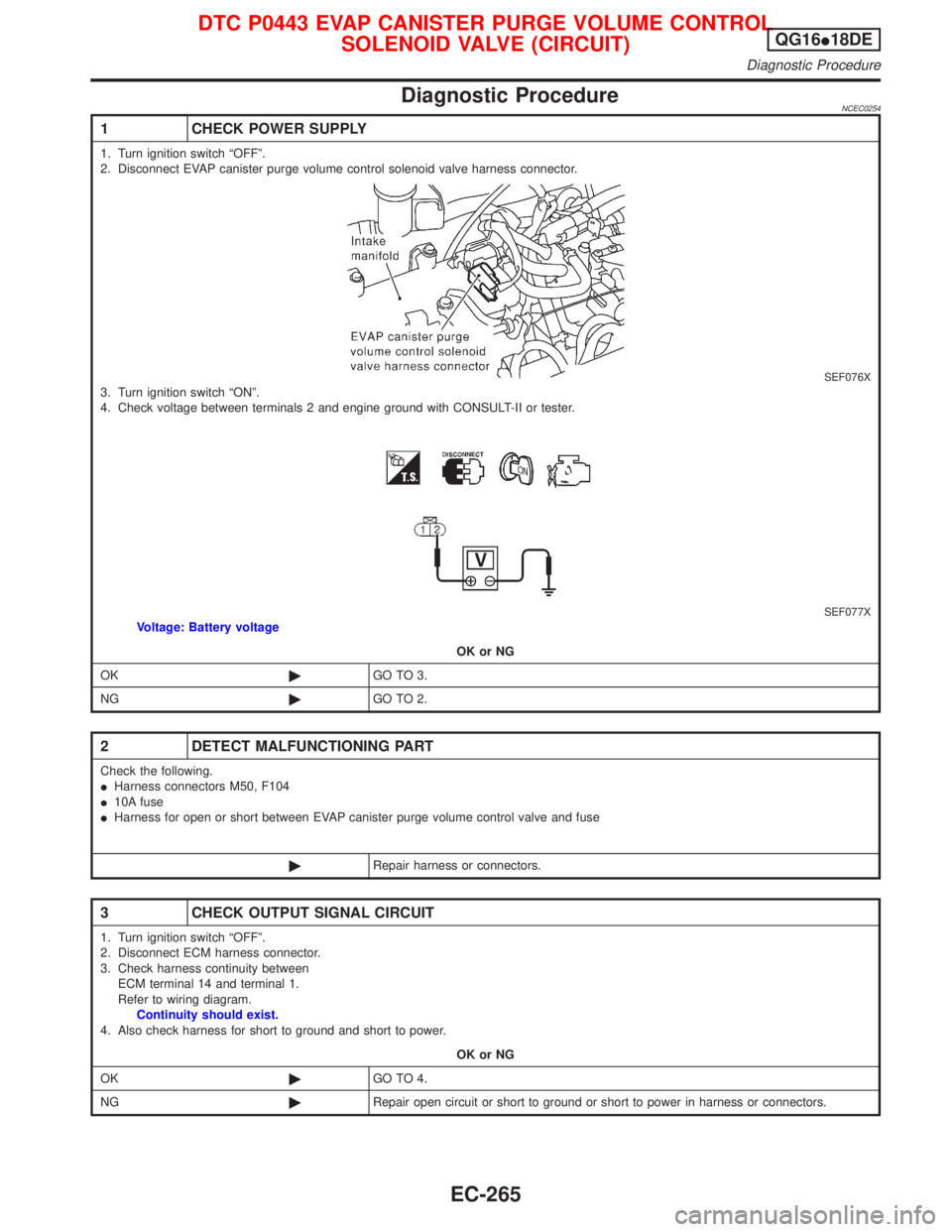
1 CHECK POWER SUPPLY
1. Turn ignition switch ªOFFº.
2. Disconnect EVAP canister purge volume control solenoid valve harness connector.
SEF076X3. Turn ignition switch ªONº.
4. Check voltage between terminals 2 and engine ground with CONSULT-II or tester.
SEF077XVoltage: Battery voltage
OK or NG
OK©GO TO 3.
NG©GO TO 2.
2 DETECT MALFUNCTIONING PART
Check the following.
IHarness connectors M50, F104
I10A fuse
IHarness for open or short between EVAP canister purge volume control valve and fuse
©Repair harness or connectors.
3 CHECK OUTPUT SIGNAL CIRCUIT
1. Turn ignition switch ªOFFº.
2. Disconnect ECM harness connector.
3. Check harness continuity between
ECM terminal 14 and terminal 1.
Refer to wiring diagram.
Continuity should exist.
4. Also check harness for short to ground and short to power.
OK or NG
OK©GO TO 4.
NG©Repair open circuit or short to ground or short to power in harness or connectors.
DTC P0443 EVAP CANISTER PURGE VOLUME CONTROL
SOLENOID VALVE (CIRCUIT)QG16I18DE
Diagnostic Procedure
EC-265
Page 711 of 2267
Wiring DiagramNCEC0277MODELS BEFORE VIN - P11U0548750
YEC784
IGNITION SWITCH
ON or START
Refer to EL-POWER.: Detectable line for DTC
: Non-detectable line for DTC FUSE
BLOCK
(J/B)
COMBINATION
METER
(SPEEDOMETER)
ECM
Refer to last page (Foldout page) VEHICLE
SPEED
SENSOR BATTERY
DTC P0500 VEHICLE SPEED SENSOR (VSS)QG16I18DE
Wiring Diagram
EC-269
Page 712 of 2267
MODELS AFTER VIN - P11U0548750
YEC073A
DTC P0500 VEHICLE SPEED SENSOR (VSS)QG16I18DE
Wiring Diagram (Cont'd)
EC-270
Page 713 of 2267

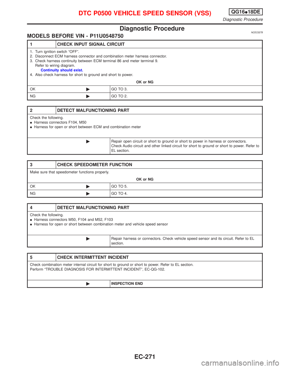
Diagnostic ProcedureNCEC0278MODELS BEFORE VIN - P11U0548750
1 CHECK INPUT SIGNAL CIRCUIT
1. Turn ignition switch ªOFFº.
2. Disconnect ECM harness connector and combination meter harness connector.
3. Check harness continuity between ECM terminal 86 and meter terminal 9.
Refer to wiring diagram.
Continuity should exist.
4. Also check harness for short to ground and short to power.
OK or NG
OK©GO TO 3.
NG©GO TO 2.
2 DETECT MALFUNCTIONING PART
Check the following.
IHarness connectors F104, M50
IHarness for open or short between ECM and combination meter
©Repair open circuit or short to ground or short to power in harness or connectors.
Check Audio circuit and other linked circuit for short to ground or short to power. Refer to
EL section.
3 CHECK SPEEDOMETER FUNCTION
Make sure that speedometer functions properly.
OK or NG
OK©GO TO 5.
NG©GO TO 4.
4 DETECT MALFUNCTIONING PART
Check the following.
IHarness connectors M50, F104 and M52, F103
IHarness for open or short between combination meter and vehicle speed sensor
©Repair harness or connectors. Check vehicle speed sensor and its circuit. Refer to EL
section.
5 CHECK INTERMITTENT INCIDENT
Check combination meter internal circuit for short to ground or short to power. Refer to EL section.
Perform ªTROUBLE DIAGNOSIS FOR INTERMITTENT INCIDENTº, EC-QG-102.
©INSPECTION END
DTC P0500 VEHICLE SPEED SENSOR (VSS)QG16I18DE
Diagnostic Procedure
EC-271